EP0162692A2 - Orthopädische Schiene - Google Patents
Orthopädische Schiene Download PDFInfo
- Publication number
- EP0162692A2 EP0162692A2 EP85303539A EP85303539A EP0162692A2 EP 0162692 A2 EP0162692 A2 EP 0162692A2 EP 85303539 A EP85303539 A EP 85303539A EP 85303539 A EP85303539 A EP 85303539A EP 0162692 A2 EP0162692 A2 EP 0162692A2
- Authority
- EP
- European Patent Office
- Prior art keywords
- splint device
- projections
- device defined
- support member
- splint
- Prior art date
- Legal status (The legal status is an assumption and is not a legal conclusion. Google has not performed a legal analysis and makes no representation as to the accuracy of the status listed.)
- Withdrawn
Links
Images


Classifications
-
- A—HUMAN NECESSITIES
- A61—MEDICAL OR VETERINARY SCIENCE; HYGIENE
- A61F—FILTERS IMPLANTABLE INTO BLOOD VESSELS; PROSTHESES; DEVICES PROVIDING PATENCY TO, OR PREVENTING COLLAPSING OF, TUBULAR STRUCTURES OF THE BODY, e.g. STENTS; ORTHOPAEDIC, NURSING OR CONTRACEPTIVE DEVICES; FOMENTATION; TREATMENT OR PROTECTION OF EYES OR EARS; BANDAGES, DRESSINGS OR ABSORBENT PADS; FIRST-AID KITS
- A61F5/00—Orthopaedic methods or devices for non-surgical treatment of bones or joints; Nursing devices ; Anti-rape devices
- A61F5/01—Orthopaedic devices, e.g. long-term immobilising or pressure directing devices for treating broken or deformed bones such as splints, casts or braces
-
- A—HUMAN NECESSITIES
- A61—MEDICAL OR VETERINARY SCIENCE; HYGIENE
- A61F—FILTERS IMPLANTABLE INTO BLOOD VESSELS; PROSTHESES; DEVICES PROVIDING PATENCY TO, OR PREVENTING COLLAPSING OF, TUBULAR STRUCTURES OF THE BODY, e.g. STENTS; ORTHOPAEDIC, NURSING OR CONTRACEPTIVE DEVICES; FOMENTATION; TREATMENT OR PROTECTION OF EYES OR EARS; BANDAGES, DRESSINGS OR ABSORBENT PADS; FIRST-AID KITS
- A61F5/00—Orthopaedic methods or devices for non-surgical treatment of bones or joints; Nursing devices ; Anti-rape devices
- A61F5/01—Orthopaedic devices, e.g. long-term immobilising or pressure directing devices for treating broken or deformed bones such as splints, casts or braces
- A61F5/04—Devices for stretching or reducing fractured limbs; Devices for distractions; Splints
- A61F5/05—Devices for stretching or reducing fractured limbs; Devices for distractions; Splints for immobilising
- A61F5/058—Splints
- A61F5/05841—Splints for the limbs
- A61F5/05858—Splints for the limbs for the arms
- A61F5/05875—Splints for the limbs for the arms for fingers
Definitions
- This invention relates to the medical arts, and, more particularly, to an improved splint arrangement for immobilizing preselected portions of the body.
- a bone fracture may require immobilization during the time period when the bone is healing.
- Bruises or other injuries to various members of the body may also require immobilization of such body member to prevent exacerbation of the injury or bruises to the body member.
- the splint devices to be used for these purposes are light in weight and of minimal size, to avoid undesired encumbrance, but still provide the desired type of protection and/or immobilization.
- the splint devices should be inexpensive to fabricate and use.
- the splint device is preferably comparatively quickly and easily installable on and removable from the body member by the appropriate attending personnel. Such a feature facilitates not only the initial installation of the splint device, but also removal thereof with minimal discomfort, so as to allow inspection and/or treatment of the body member. Care must be taken, however, in many applications, to insure that the device is "childproof," that is, not easily removable or manipulatable by children.'
- splint devices which may be rapidly installed on the fractured or otherwise injured body member.
- one splint device be adaptable to a variety of sizes of body members so that the inventory of the attending personnel may be minimized.
- a semi-rigid construction is also desired in many applications of a splint device to allow conformation of the splint device to a particular shape of the body member.
- the splint device must have sufficient strength and rigidity to provide the protection desired on any specific application.
- U. S. Patent No. 1,144,103 discloses a finger splint consisting of a pair of thin pliable strips, secured together at their centers, to extend at right angles to each other, the strips being bent inwardly toward each other at a point adjacent the center to form an elongated-framework, the free ends of said strips being provided with slots.
- U. S. Patent No. 1,229,633 describes a finger guard consisting of a plurality of strips of pliable metal, wire, or other suitable material, twisted about each other upon their approximate centers in such a manner that a plurality of extensions result, which, upon being bent or contoured to the finger, extend in a substantially parallel relation.
- the guard is adapted to be held in place on the member by adjesive strips, cord, or other suitable means.
- U. S. patent No. 3,692,022 describes a digital splint adapted for use on a finger.
- the splint includes a generally cylindrical, rigid, hollow member, in which the finger is inserted, and a spring clip member which engages the finger through a pair of mutually opposed slots in the hollow member, and which secures the hollow member to the finger.
- U. S. Patent No. 2,506,464 pertains to what is referred to as a finger stall, comprising a plurality of strips of malleable material, the strips being pivotally held together one upon the other at their central portions, the strips being pivotally turnable out of registry with each other and the ends of the strips being turned in the same direction form U-shaped elements having parallel positioned legs which are pivotally adjustably positionable around an injured member, one leg element is curved transversely to provide stiffness to the leg and to provide a formed curvature in the stall for close fitting around the injured member.
- This splint has a paddle shaped semi-pliable plate of a material having the inherent quality of being easily bent manually into various forms, and of retaining such forms when so bent.
- the plate has a substantially rectangular blade portion, and a portion of the blade continuing from one end thereof and gradually decreasing in width at one side of its axis and somewhat more abruptly decreasing in width at the other side of its axis. Digits can be bandaged to the blade.
- U. S. Paetnt No. 1,245,8.58 relates to a surgical splint consisting of a pair of pliable strips adjustably connected together between their ends and extending at substantially right angles to each other. The strips are bent in parallel relationship for engagement upon a finger.
- the present splint device meets the above mentioned desiderata, and is unique in providing a simple device for effective immobilization and protection of a broken or injured body member.
- a splint device according to the principles of the present invention is adaptable to a wide range of body member sizes and is adjustable thereto and securely retainable thereon. The device does not retain water or perspiration.
- the splint device of the present invention is inexpensive, comparatively light in weight, of minimal bulk, and may be rapidly and easily installed on the body member. "Childproofing" of the splint device may also be provided.
- splint device described herein is shown as utilized on human body members, the invention is not so limited. Splint devices of the present invention may also be utilized advantageously in veterinary medicine in treatment of animals. f
- the present invention comprises a splint device for the immobilization of-a body member because of fractures or other injuries to the body member.
- a body member may, for example, be a digit, such as a finger or toe.
- the splint device comprises a splint means comprising a ring-like base portion adapted to fit around a digit in proximity to the digit's proximal end. Extending from the base portion, there is provided a plurality of essentially rigid or semi-rigid elongated support members which are coupled to the base portion of their base ends and are spaced apart around the base portion. The elongated support members are positionable adjacent the contained digit, preferably on more than one of its sides.
- Each of the support members terminates at a free end which is in the vicinity of, or beyond, the distal end of the digit.
- support members may be "mushroom” type projections and the retaining means may be a comparatively flexible strap.
- the flexible strap has walls defining a mushroom engaging slot and is provided with a plurality of self retaining clasp means thereon to allow adjustment to any desired diameter as it is wrapped around the support members.
- cap means which may be installed over the free ends of the support members for retention thereon.
- the cap means may, if desired, be made "childproof" to prevent the undesired removal of the cap means by small children.
- the ring-like base portions may be of a fixed diameter or, alternatively, may be provided with radial expansion capability to provide a predetermined circumferential expansion.
- the radial expansion capability may be achieved by axially extending slots, by "zig-zag" interconnections between the support members, or combinations thereof.
- the circumferential expansion characteristic permits utilization of one sized splint device on a variety of sizes of body members.
- an embodiment, generally designated 2 of the present invention there is illustrated an embodiment, generally designated 2, of the present invention.
- an improved splint device generally designated 4.
- the splint device 4 is comprised of a splint means 6 having a base portion 10.
- the base portion 10, in the embodiment 2, has a fixed circumferential dimension. That is, the base portion 10 does not have expansion capability.
- the base portion 10 is fabricated to be in a ring-like configuration as illustrated.
- the splint device 4 is semi-rigid, that is, it has a predetermined degree of flexibility to allow utilization as described herein, but still has sufficient rigidity to provide the immobilization of the body part to which it is applied.
- the splint device 4 also comprises a plurality of elongated support members 12 having base ends 11 coupled to the base portion 10 and free ends 13.
- the support members 12 are unitarily fabricated with the base portions 10 by, for example, molding so as to provide an integral splint means 6.
- the plurality of elongated support members 12 is four, spaced equally around the base portion 10. It will be appreciated that the number of elongated support members 12 may be more or less than four.
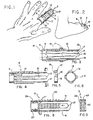
- the support members 12 terminate at the free end 13 which is in the vicinity of or extends past the distal end of a digit such as the finger 7 of Figure 1 or the toe 9 of Figure 2.
- the free end 13 is very close to the distal end of the digit. This can be accomplished by cutting off any excess of the support member extending beyond the distal end of the digit to accommodate any length of digit.
- the plurality of support members 12 of the splint means 6 of the splint device 4 have a plurality of generally saw-toothed shaped projections 14 on the outer surfaces 15 thereof.
- the saw-tooth projections 14 extend generally circumferentially.
- the splint device 4 also comprises a compression means generally designated 17, as illustrated in Figure 5.
- the compression means 17, in the embodiment 2, as illustrated in Figure 5, is in the form of a ring having an outer surface 18 and and inner surface 19.
- the inner surface 19 is provided with a plurality of internal ridges, generally designated 16, which are complementary to the projections 14 on the support members 12 and the internal ridges 16 are adapted to engage the projections 14 to retain the compression means 17 thereon, as illustrated in Figures 1, 2, and 3.
- a plurality of compression means 17 may be provided having different internal diameters to provide varying degrees of compression to thereby accommodate various diameters of the body member to which it is applied.
- the splint means 6, when utilized, for example, on a fractured finger as illustrated in Figures 1 and 3, or a fractured toe as illustrated in Figure 2, is slipped onto the digit from the distal end toward the proximal end thereof.
- Compression means 17, of an appropriate size is selected and inserted around the support members 12 to the appropriate position desired.
- the diameter of the compression means 17 is selected to provide, at any given location along the axial extent of the support members 14, the desired degree of compression thereof.
- Figure 1, for example, illustrates two such compression means 17 installed. The smaller the internal diameter of the compression means 17, the greater will be the degree of compression of the support members 12 against the digit to which it is applied. Therefore, by selecting the appropriate size of the compression means 17, the spacing apart of the support members 12 from each other may be varied throughout the axial length, from the base end 11 to the free end 13.
- the splint device 4 may also comprise an end cap for engagement with the free ends 13 of the support members 12 to protect the distal end of the digit to which the splint device 4 is applied. Because of the preferred lightweight and semi-rigid characteristic of the material from which the splint means 6 is fabricated, it has been found that the free ends 13 may tend to catch on various objects and thus apply inadvertent and undesired strain or force to the digit.
- An end cap, generally designated 5, is illustrated in Figure 7, for utilization in the embodiment 2.
- the end cap 5, is fabricated in a generally cup-shaped configuration, having an end wall 21 and a circumferential wall 23.
- the end cap 5 has an open end 25 opposite the end wall 21.
- the internal surface 27, of the end cap 5 is provided with a plurality of ridges 29 which are generally the same as the ridges 16 of the compression means 17, and serve the same function. Utilization of the end cap 5, of course, requires that the projections 14, on the support members 12, extend to regions adjacent the free ends 13. The end cap 5 is pushed onto the plurality of support members 12, and the projections 14 thereon engage the ridges 29 to retain the end cap 5 in place.
- the end cap 5 may be made "childproof" by any of the types of conventional childproof structures utilized in other applications.
- an internal tab 31 may be provided on the internal surface 27, extending radially inwardly a greater distance than the ridges 29.
- the flexibility of the material from which the preferred embodiment is made allows the internal tab 31 to bend toward the end wall 21 during installation. Therefore, it clears projections 14 when moved in the direction indicated by the arrow 33 to allow installation on the support member 12.
- the internal tabs prevent inadvertent removal by engagement with the projections 14 when the end cap 5 is moved in the direction indicated by the arrow 35.
- children will have difficulty depressing the support members 12 sufficiently to clear the internal tab 31, but adults will not be so hampered.
- the splint means 6 the compression means 17, and, if desired, the end cap 5.
- FIGS 8 and 9 illustrate another embodiment, generally designated 3, of the present invention, which is generally similar to the embodiment 2 described above.
- a splint means 39 generally similar to the splint means 6 described above, except that the projections 20 provided on the support members 41 are in the form of screw threads such as the Acme screw threads illustrated.
- a compression means 43 is generally similar to the compression means 17 described above, except that the internal surface 45 thereof is provided with corresponding screw threads 22 for engagement with the screw threads 20 on the support members 41.
- the embodiment 3 may be utilized in a manner identical to that described above, except that the compression means 43 is threaded onto the splint means 39.
- an end cap generally similar to the end cap 5 shown in Figure 7, may also be utilized in the embodiment 3, except that the internal surface of such an end cap is provided with matching screw threads for engagement with the screw threads 20 on the support members 41.
- a plurality of compression means 43 may be provided for installation on the splint means 39 and the internal diameters of the variety of compression means 43 may be varied so that differing degrees of compression may be obtained as the compression means 43 is threaded from the remote ends 13' of the support members 41 toward the base ends 11' thereof.
- An end cap utilized in the embodiment 3 may, if desired, also be provided with childproofing, except that the internal tab, such as the internal tab 31 shown in Figure 7, would extend circumferentially rather than axially, so that it would engage one of the support members 14 to prevent further unthreading thereof.
- the materials from which the embodiments of the present invention may be fabricated may, for example, be polyvinyl chloride, polyvinyl propylene, nylon, or the like, as these materials, and other similar materials possess the desired degree of rigidity and flexibility, as well as lightness and minimal bulk preferred.
- the various parts of the splint devices of the present invention are, preferably, injection molded to minimize the cost thereof.
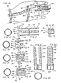
- FIG 10 illustrates an embodiment generally designated 51 of the present invention to provide for such immobilization.
- the splint device generally designated 53 of embodiment 51 is applied to a human hand, generally designated 49.
- the embodiment 51 comprises a splint means 55 , generally similar to the splint means 6 described above in connection with embodiment 2, or the splint means 39 described above in connection with the embodiment 3.
- the splint means 55 has a base portion 10' and a plurality of elongated support members 12'.
- a compression means 17' is shown installed as part of the splint device 53, and there is also provided an end cap 34 , which is illustrated in greater detail in Figure 13.
- a rearwardly extending rear support member 24 which extends from the base portion 10' in a directior opposite the direction of the elongated support members 12', and the rearwardly extending member 24 is positionable against the palm of the hand as illustrated in Figure 10.
- the rearwardly extending member 24 would be positioned against the sole or bottom of the foot, extending toward the heel.
- the rearwardly extending member 24 bears against the palm of the hand and, preferably, is comparatively rigid to prevent bending or curling of the fingers (or toes as the case may be).
- the rearwardly extending member 24 is, preferably, held in the position as illustrated in Figure 10 by one or more restraining bands 28. Two such restraining bands are shown in Figure 10.
- a plurality of small protuberances 30 are incorporated on the rearwardly extending member 24.
- the restraining bands 28 have first walls generally designated 57, defining a plurality of apertures 32, which are so sized as to provide a substantially interference fit with the protuberances 30 on the rearwardly extending member 24.
- the restraining bands 28 may be fabricated from the same material as the splint means 55, compression ring 17' and end cap 34, or, alternatively, if resiliency as well as flexibility is desired, may be fabricated from a rubber-like material.
- the end cap 34 is provided with internal screw threads 59 to match the screw threads 61 on the support members 12'.
- the end cap 34 may also be provided with a plurality of slits in the peripheral wall 61 thereof, adjacent the open end 63 to allow radial expansion thereof to accommodate different radial dimensions of the remote ends of the support members 12'.
- the end cap 34 may be utilized, for example, in the embodiment 3 as described above.
- the end cap 34 may be made "childproof" in a manner similar to that described above, by providing an inwardly extending tab 67 on the inner surface 59, which during threading engagement with the threads 61 on the support members 12' freely rides over the threads, but in the unthreading thereof, engages the edges of one of the supporting members 12' to prevent further unthreading by a child.
- the cap may be radially distorted so that the tab 67 clears the members to allow complete removal of the end cap 34. Such radial deformation of the end cap 34 is generally beyond the capability of small children.
- the base portion of the splint means is of a tubular, ring-like configuration, having a given radial dimension. While, in the preferred embodiments, the semi-rigid characteristic of the material from which the splint means is fabricated allows radial deformation, the circumferential extent of the base portion is fixed. It has been found that, in accordance with the principles of the present invention, in many applications it is desirable to have a circumferential expansion capability in the base portion, while still retaining the basic tubular configuration on a body member as described herein. Additionally, the base portion of the present invention may be selectively fabricated in any desired cross-sectional shape, such as round, as illustrated herein, or other shapes to accommodate specific body members.
- the circumferential expansion capability allows utilization of the splint device of the present invention on a variety of different sized body members. Such circumferential expansion capability, together with the radial deformation capability, increases the utility of the splint devices according to the principles of the present invention.
- the circumferential expansion capability may be provided by incorporating expansion joints in the base portion of the splint means.
- FIGS 11 and 12 illustrate an embodiment of the present invention generally designated 70, in which there is provided a splint means.72, which, in general, is similar to the splint means 6 and 37 described above in that it comprises a base portion 36 and a plurality of support members 74 extending therefrom.
- the base portion 36 of the splint means 72 has an expansion means 73, generally comprised of first walls 44 defining a slot 76 aligned with each of the support members 74 and the slot 76 extends into the support members 74.
- the slots 76 together with the spacing "a" between adjacent support members 74, allow a radial expansion of the base portion 36 which thereby allows a circumferential expansion of the base portion 36 to accommodate different sized digits.
- FIGS 14 and 15 illustrate another embodiment of the present invention, generally designated 80, in which there is illustrated a splint means, generally designated 82, having a base portion 38 and a plurality of elongated support members 84 extending therefrom.
- Expansion means, generally designated 86 are provided in the base portion 38 of the splint means 82 by means of walls 46 defining a plurality of slots 88.
- the slots 88 are in staggered, overlapping, configuration, with alternating slots 88 extending from regions adjacent the base end 11' of the elongated support members 84 into the base portion 38, and other slots 88 extending from the remote end 38' of the base portion 38.
- the slots 88 thereby allow radial expansion and circumferential expansion of the base portion 38 to accommodate a variety of digit sizes.
- Figures 16 and 17 illustrate another embodiment, generally designated 90, of a splint device 92 according to the principles of the present invention, having a splint means 94.
- the splint means 94 (as well as the splint means 72 and 84 of the embodiments 70 and 8 0, respectively, described above) may be generally similar to the splint means 6 and 37 described above.
- the expansion means, generally designated 96, in the base portion 40 of the splint means 94 is provided with first walls 48 defining slots 98, extending axially from the remote end 40' of the base portion 40, through the base portion and into each of the support members 100.
- Second walls, generally designated 102, are also provided in the expansion means 96, to define slots 104 extending into the base portion 40 in a direction opposite the slots 98.
- the expansion means 96 of Figures 16 and 17 allows even greater circumferential expansion than the expansion means 86 and 73 described above.
- FIGs 18 and 19 illustrate yet another embodiment, generally designated 110, of a splint device 112 having a splint means 114.
- the splint means 114 is generally similar to the splint means 6 and 37 described above, and is provided with a base portion 116, having a remote end 116'.
- the base portion 116 has first walls, generally designated 50, defining slots 118, extending through the base portion 116 and into the support members 120, similar to the slots 98 described above in connection with the embodiment 90 illustrated in Figures 16 and 17.
- second walls 52 defining a pair of slots 122 between adjacent support members 120, to provide even greater allowable circumferential expansion.
- Figure 20 illustrates yet another embodiment, generally designated 130, of the present invention, providing expansion capability in the base portion.
- a splint device 132 having a splint means 134, which is provided with a base portion 136, having a remote end 136' and a plurality of elongated support members 138 extending from the base portion 136.
- the expansion means 140 of the embodiment 130 is achieved by first walls 142 in the base portion 136, defining a plurality of slots 144 extending into the base portion from the remote end 136' thereof, both in alignment with each of the support members 138, as illustrated at 144a, as well as intermediate each of the support members 138 as illustrated at 144b.
- the base portion 136 also has second walls 146, defining a pair of slots 148, between each of the support members 138.
- the expansion means 140 provides an even greater allowable circumferential expansion of the base portion 136.
- the base portion was permanently coupled, for example, by molding, to the supporting members.
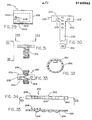
- Figures 24 and 25 illustrate an embodiment, generally designated 150, of a splint device, generally designated 152, having a splint means, generally designated 154, comprised of a base portion 156 and a plurality of separate support members.158.
- the base portion 156 is a ring-like structure and may be circumferentially non-extendible, similar to the base portion 10, for example, described in connection with embodiment 2 above. Alternatively, it may be provided with any of the expansion means described above.
- the base portion 156 is provided with expansion means generally designated 155, which, for example, may comprise a plurality of slots 157, and is generally similar to the expansion means 86, as illustrated in Figures 14 and 15. However, any other desired type of expansion means may equally well be utilized in the base portion 156.
- the base portion 156 is also provided with a plurality of spaced apart radially extending "mushroom” shaped projections 160, in a predetermined spaced array around the circumference.
- the projections 160 are illustrated in a circumferentially aligned array. However, the projections may, if desired, be in a circumferentially staggered relationship.
- a plurality of support members 158 may be utilized with the base portion 156. As illustrated in Figure 25, the support member 158 is provided with at the base end 158' thereof with a "keyhole" shaped slot therethrough, generally designated 162. The keyhole shaped slot is adapted to be positioned over the mushroom shaped projections 160 for removable coupling on the base portion 156. It will be appreciated that embodiment 150 allows for the positioning of the support members 158 in other than the fixed locations as provided in the embodiments described and illustrated above. Thus, the attending personnel utilizing the splint device 152 may position several support members 158 closely adjacent each other on the base portion 156, and leave other areas free of support members.
- the positioning of the support members 158 around the base portion 156 will provide not only immobilization and/or protection, but may also provide access to other portions of the body member for which more frequent treatment may be required.
- the utilitarian value of the present invention is further enhanced by the structure of embodiment 150 in particular applications where access to various portions of the injured body member is required, and yet the splint type function is also necessary.
- the support members 158 are shown with projections comprising screw threads similar to that illustrated in embodiment 3 described above. It will be appreciated that the saw-tooth type projections as illustrated in embodiment 2, or any of the other projections on the support members as described herein, may advantageously be utilized.
- Embodiment 150 also provides another advantage in that the support members 158 may be pivotally rotated in the directions indicated by the arrow 162 after installation on the base portion 156. This additional feature allows the attending personnel to provide even greater positional capability of the support members along the injured body member to which the splint device 154 is applied. In other applications, however, it may be desired to provide a more secure coupling between the support members 158 and the base portion 156. Such more secure or permanent type coupling may be provided by appropriately bonding, by a suitable adhesive or the like.
- the support members of a splint device may be unitarily fabricated and thus fixedly coupled to the base portion, they may be detachably coupled, or any combination thereof.
- FIGS 21, 22, and 23 illustrate another embodiment, generally designated 170, of the present invention, in which there is provided a splint device, generally designated 172, having a splint means 174, comprised of a base portion 176, and a plurality of support members 178, coupled to the base portion 176.
- a splint device generally designated 172
- a splint means 174 comprised of a base portion 176
- support members 178 coupled to the base portion 176, and in diametrically opposed relationship.
- Projections such as the screw threads 180 may be provided on the support members 178, although, it will be appreciated, any of the other projections on the support members, as described herein, may be advantageously utilized in embodiment 170.
- the base portion 176 is shown as including expansion means 182, which, in general, is similar to the expansion means 140 described in connection with Figure 20.
- the two support members 174 are of greater circumferential extent and thus more rigid than the support members described above.
- the more rigid type of support member may be desired to provide additional protection and/or immobilization to a given body member to which the splint device 172 is applied.
- the support members 178 may be provided with a plurality of apertures 181 extending therethrough. Such apertures 181 allow for the drainage of water or perspiration from the body member to which it is applied.
- embodiment 170 is advantageously utilized on a body member over which bandages or other types of dressings or the like have previously been applied for treatment of the injured body member.
- the splint device 172 may also comprise a compression means such as the compression means 184 illustrated in Figure 23, which is provided with internal threads matching the threads 182 on the support members 178.
- An appropriate end cap such as the end cap 34 shown in Figure 13, may also be utilized as required. Because of the greater circumferential extent and more massive structure associated with embodiment 170, it has been found that such an embodiment may be advantageously utilized on body members comprising not only the digits, but also any appropriate other body member such as arms, legs, or the like, to the extent that such structure may be appropriately installed and utilized.
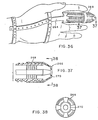
- FIGs 26, 27, 28, and 29 illustrate another embodiment, generally designated 190, of a splint device, generally designated 192, of the present invention.
- the splint device 192 comprises a splint means generally designated 194, having a base portion 196 and a plurality of support members 198, coupled thereto.
- Base portion 196 as illustrated in Figures 26, is shown as unitarily molded with the support members 198.
- the support members 198 may be detachably coupled to the base portion 196 in a manner as illustrated in embodiment 150, described above.
- the base portion 196 is shown as a circumferentially fixed base portion.
- the base portion 196 may, if desired, be provided with expansion means to provide circumferential expansion capability as described above.
- the mushroom shaped projections 200 Integral with the support members 198, there are provided a plurality of "mushroom” shaped projections generally designated 200, extending therefrom.
- the mushroom shaped projections 200, on each of the support members 198 are in an axially spaced apart array and are axially spaced a preselected distance from the mushroom shaped projections on each of the other support members 198, to provide an axially staggered non-circumferentially aligned array.
- the mushroom shaped projections 200 have a head portion 200' and a stem portion 200".
- Figures 27 and 28 illustrate a compression means, generally designated 202, usefull with the splint means 194 illustrated in Figure 26.
- the compression means 202 is a strap-like member 204, having a "keyhole" shaped aperture, generally designated 206 therethrough, in regions adjacent a first end 208 which is disposed in a spaced apart relationship to a second end 210 thereof.
- a plurality of upstanding catch means 212 Adjacent the second end 210, there is provided a catch receiving aperture 214 which is adapted to engage one of the upstanding catch means 212.
- the keyhole shaped aperture 206 is placed over the mushroom shaped projection 200 and the enlarged portion of the keyhole shaped aperture allows it to fit over the head 200' of the mushroom shaped pro- je ction 200.
- the stem 200" of the mushroom shaped pro- j e ction 200 is then positioned in the slot of the keyhole shaped aperture 206, and the restraining means 202 is wrapped around the splint means 194.
- the aper- t u re 214 is then positioned over one of the catch means 212 for securing of the strap means 204.
- each of the support members 198 allows the strap-like member 204 to be securely wrapped on the splint means 194. It will be appreciated that, depending upon the particular configuration of the body member to which the splint device 192 is applied, the various support members 198 may be in radially different positions so that restraining means 202 may engage less than all of the support members 198. As many restraining means 202 may be utilized on the splint means 194 in as many locations as desired.
- a cap means, generally designated 220, is illustrated in Figure 29, and has particular utility with embodiment 190.
- the cap means 220 is generally similar to the cap means described above, having an end wall 222 and a peripheral wall 224. However, the open end 226 is provided with a pair of opposed slots 228, diametrically opposed from each other in the peripheral wall 224 which engage and lock onto the mushroom shaped projections 200 of the support members 198.
- FIG 30 illustrates another compression means, generally designated 230, which is useful in the practice of the present invention and, in particular, embodiment 190 described above.
- the compression means 230 is generally similar to the compression means 202 in that it is provided with a strap-like portion 232, upon which there are provided a plurality of catch means 234 and a catch receiving aperture 236. There is also provided a head portion 238, extending substantially at right angles to the strap portion 232 and the head portion 238 has a pair of mushroom engaging apertures 240 therein.
- the mushroom engaging apertures 240 are spaced apart a distance corresponding to the axial spacing of the mushroom shaped apertures 200 on the support members 198.
- mushroom accepting apertures 240 are positioned adjacent a pair of mushroom shaped projections 200 on any of the support members 198 and moved in the direction of arrow 241 to "lock" the compression means 230 in place.
- the strap portion 132 wrapped around the digit and/or additional support members 198, and the aperture 236 is positioned on one of the catch means 234 for retention thereon. It will be appreciated that more than one of the compression means 230 or compression means 202 may be utilized in conjunction with the splint means 194.
- compression means illustrated above in connection with embodiments 2, 3, and 10 have generally been ring-shaped members. It has been found, however, that strap-like compression means may also be advantage- ously utilized with such embodiments which incorporate either thread-like projections on the external surface of the support members, or saw-toothed type projections on the support members, or, alternatively, on those embodiments wherein there are not provided any projections on the support members.
- Figures 33 and 34 illustrate a compression means, generally designated 250, which may be advantageously utilized with splint means of the type described herein, either having projections on the external surfaces of the support members or free of such projections on the support members.
- the compression means 250 comprises a strap-like member 252, having an outer surface 254, and an inner surface 256.
- the strap-like member 252 is adapted to be wound around the splint means upon which it is utilized.
- the strap-like member 252 is also provided with catch means 258, extending outwardly from the outer surface 254 and a catch receiving aperture 260 is provided for engagement with one of the catch means 268.
- a plurality of support member engaging projections 262 extend outwardly from the inner surface 256 of the strap means 252.
- the support member engaging projections 262 engage the sides of the support members of a splint means of the present invention.
- the catch receiving aperture 260 is positioned over one of the catch means 258.
- the compression means 250 may be advantage-ously utilized in any splint device described herein. Further, the compression means 250 need not be positioned externally all of the support members on any one splint means, but may be intertwined as desired to provide a particular compression configuration.
- the ring-like compression means such as the compression means 12 and 22 described above, have a fixed circumferential extent. In some applications, it may be desirable to provide a compression means which has circumferential expansion capability.
- Figures 31, 32, and 33 illustrate a restraining means, generally designated 250, having such a circumferential expansion structure.
- the compression means 250, illustrated in Figures 31, 32, and 33 is particularly adapted for utilization with the splint means 194 illustrated in Figure 26.
- suitable modifications to such a structure may make it adaptable to any of the splint devices described herein, by inclusion, for example, of internal projections such as the internal projections 262 described above in connection with Figures 33 and 34.
- the compression means 250 has a head portion 252, generally similar to the head portion 238, and is provided with walls 253 defining a pair of slots 254, adapted to engage adjacent mushroom shaped projections 200 on a support member 198.
- the slots 254 are in spaced apart relationship, corresponding to the axial spacing between adjacent mushroom shaped projections 200.
- the compression means 250 also comprises an expansion ring 256 which is generally similar to a spring-like ring which is resiliently flexible. As shown, the expansion ring 256 is in a generally Z-shaped configuration, and the cross-sectional areas associated with each part of the expansion ring 256, together with the material from which it is comprised, defines both the expansion capability and resiliency thereof.
- internal projections on the head portion 252 may be provided, corresponding to the circumferential spacing between adjacent support members on a splint device according to the principles of the present invention. In such applications, where the mushroom shaped projections 200 are not provided, then the slots 254 need not be provided.
- the nominal diameter of the base portion may be on the order of 1" and in the range of 1 ⁇ 4" to 11 ⁇ 2".
- Expansion means may, of course, in those embodiments incorporating such structure, increase the circumference of the base portion to values greater than that provided by the nominal diameter.
- support members may be substantially equally spaced around the circumference of the base portion and on the order of 1 ⁇ 4" wide in the circumferential direction.
- the thickness of the base portion and support members may be on the order of 1/16" to 1/8", although greater or lesser thicknesses may be utilized as desired.
- the axial length of the elongated support members may be on the order of 3", but may be severed to any desired length.
- the circumferential extent of the support members 174 of embodiment 170 of Figurs 21, 2, and 23 may, in order to provide more rigid support, be on the order of 3/4" in circumferential extent.
- the compression means may be fabricated to provide compression diameters when installed on the order of 1/ 4 " to 11 ⁇ 2", although longer or smaller dimensions may be utilized in particular applications.
- the splint 264 has an end cap 266.
- the end cap 266 has a ring portion 268 and end portion 270 in a unified structure which cojoins the function of the separate rings and end caps discussed above.
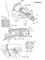
- Figures 39 to 41 show preferred splints.
- Splint 272 has an opening 274 to permit some flexing of the finger at the knuckle.
- the embodiment of Figure 40 has two rubber rings 276 each of which have holes receiving projections 278 extending from the bottom surface of the splint 280.
- the element 282 is less extensive than element 24 of Figure 10, allowing for wrist flexure.
- Figures 42 to 44 show opening 284.
- the elements 286 at each side of the figure have a thicker portion 288 and a thinner portion 290.
- the thinner portion 290 can flex when the knuckle is flexed.
- the thicker portion 288 is essentially rigid, thus a kind of hinge-like action is provided.
- the openings 292 provide air flow for sweat evaporation and drainage of the contained body member for better cleanliness and comfort for the patient.
- the end cap 294 is as has been already discussed.
- the end cap generally extends from the distal end of the finger rearwardly past the first joint so that the ring portion of the end cap provides compression force rearwardly of the first joint for maximum effect and comfort.
- the end cap can be partially unscrewed to reduce compression, if desired, such as when swelling occurs.
- the inner surface 296 of the splint which normally abuts the contained body member have grooves and ridges as shown to facilitate drying and air circulation.
- the exterior surface 298 of the underside of the splint is provided with a series of lands 300 and grooves 302.
- the splint is normally made of plastic and the grooves 302 being of lesser thickness are adapted to take a "crease" or “set” when the splint is manually bent so that the splint can be set on any desired degree of curvature and thereby better conform to the configuration of the body member.
Landscapes
- Health & Medical Sciences (AREA)
- Nursing (AREA)
- Orthopedic Medicine & Surgery (AREA)
- Engineering & Computer Science (AREA)
- Biomedical Technology (AREA)
- Heart & Thoracic Surgery (AREA)
- Vascular Medicine (AREA)
- Life Sciences & Earth Sciences (AREA)
- Animal Behavior & Ethology (AREA)
- General Health & Medical Sciences (AREA)
- Public Health (AREA)
- Veterinary Medicine (AREA)
- Orthopedics, Nursing, And Contraception (AREA)
Applications Claiming Priority (4)
| Application Number | Priority Date | Filing Date | Title |
|---|---|---|---|
| US61268384A | 1984-05-21 | 1984-05-21 | |
| US612683 | 1984-05-21 | ||
| US06/734,328 US4644941A (en) | 1984-05-21 | 1985-05-15 | Orthopedic splint arrangement |
| US734328 | 1985-05-15 |
Publications (2)
| Publication Number | Publication Date |
|---|---|
| EP0162692A2 true EP0162692A2 (de) | 1985-11-27 |
| EP0162692A3 EP0162692A3 (de) | 1987-05-27 |
Family
ID=27086831
Family Applications (1)
| Application Number | Title | Priority Date | Filing Date |
|---|---|---|---|
| EP85303539A Withdrawn EP0162692A3 (de) | 1984-05-21 | 1985-05-20 | Orthopädische Schiene |
Country Status (8)
| Country | Link |
|---|---|
| US (1) | US4644941A (de) |
| EP (1) | EP0162692A3 (de) |
| KR (1) | KR890005142B1 (de) |
| AU (1) | AU584615B2 (de) |
| DK (1) | DK220285A (de) |
| FI (1) | FI852017A7 (de) |
| NO (1) | NO852021L (de) |
| NZ (1) | NZ212152A (de) |
Cited By (3)
| Publication number | Priority date | Publication date | Assignee | Title |
|---|---|---|---|---|
| WO1990014057A1 (de) * | 1989-05-19 | 1990-11-29 | Waldemar Link Gmbh & Co. | Fingerschiene |
| WO2011044595A1 (de) | 2009-10-16 | 2011-04-21 | Austria Wirtschaftsservice Gesellschaft mit beschränkter Haftung | Verfahren zum herstellen einer stütz- oder schutzeinrichtung für einen körperteil |
| GR1009032B (el) * | 2016-04-13 | 2017-05-12 | Νεκταριος Βασιλειου Μπογρης | Ναρθηκας δακτυλων ανω ακρων |
Families Citing this family (18)
| Publication number | Priority date | Publication date | Assignee | Title |
|---|---|---|---|---|
| US4813406A (en) * | 1984-05-21 | 1989-03-21 | Ims Limited | Orthopedic splint arrangement |
| US4899737A (en) * | 1988-09-14 | 1990-02-13 | Lazarian Vartan J | Splint for complete circumferential immobilization of an extremity or a terminal member of an extremity |
| US5095897A (en) * | 1990-09-21 | 1992-03-17 | Clark E Nelson | Orthopedic splint and method of constructing same |
| US5267945A (en) * | 1991-04-24 | 1993-12-07 | David Doctor | Finger splint for treating pip joint injuries |
| US6575925B1 (en) * | 2000-05-18 | 2003-06-10 | Apothecary Products, Inc. | Finger splint |
| US7354270B2 (en) * | 2003-12-22 | 2008-04-08 | Align Technology, Inc. | Surgical dental appliance |
| US20060069334A1 (en) * | 2004-09-24 | 2006-03-30 | Moskowitz Barry M | Compact universal splint apparatus for focused immobilization such as of a single digit of the foot or hand, and method |
| US7849610B2 (en) * | 2006-03-03 | 2010-12-14 | Clough James G | Orthopedic shoe appliance and method |
| ES2440277T3 (es) | 2008-05-06 | 2014-01-28 | J.W. Barry Bruckmann | Estructuras de movilización musculoesquelética |
| US8308756B1 (en) * | 2009-03-11 | 2012-11-13 | Al Deskiewicz | Ring remover device and method |
| US8262599B2 (en) * | 2009-04-09 | 2012-09-11 | Iq Medical Devices, Llc | Splint composition and method for using same |
| US10143183B2 (en) * | 2012-03-29 | 2018-12-04 | Dr. Buzby's Innovations, Llc | Animal toenail grips |
| US9056014B2 (en) | 2012-12-27 | 2015-06-16 | Wright Medical Technology, Inc. | Device and method for fixation for bone or soft tissue deformity of digits |
| US9931235B2 (en) * | 2014-12-12 | 2018-04-03 | Harris Corporation | Passive locking hand exoskeleton |
| WO2019033103A1 (en) * | 2017-08-11 | 2019-02-14 | West Pharmaceutical Services, Inc. | AUTOMATICALLY RETRACTABLE RETRACTABLE COLLAR AND METHOD OF USE |
| USD1019961S1 (en) * | 2020-12-11 | 2024-03-26 | Manometric Holding B.V. | Splint |
| USD1019960S1 (en) * | 2020-12-11 | 2024-03-26 | Manometric Holding B.V. | Splint |
| US12193960B1 (en) | 2021-10-06 | 2025-01-14 | Andrew Page | Finger straightening device |
Family Cites Families (12)
| Publication number | Priority date | Publication date | Assignee | Title |
|---|---|---|---|---|
| US1144103A (en) * | 1913-08-08 | 1915-06-22 | Edmund Dempster Brant | Surgical device. |
| US1389525A (en) * | 1920-02-21 | 1921-08-30 | John K Mosby | Surgical appliance |
| US1837691A (en) * | 1927-07-01 | 1931-12-22 | Rembert H Thigpen | Surgical splint |
| FR752041A (fr) * | 1933-03-07 | 1933-09-15 | Dispositif orthopédique | |
| US2273028A (en) * | 1939-01-07 | 1942-02-17 | Warren S Eaton | Splint |
| US2528456A (en) * | 1949-03-07 | 1950-10-31 | Evergrip Inc | Fixing splint for injured body appendants |
| US2548378A (en) * | 1949-12-06 | 1951-04-10 | Ewald H Kleinfeld | Finger splint |
| CH305564A (fr) * | 1950-06-16 | 1955-02-28 | Kissilevski Pauline | Appareil pour la correction de déformations du gros orteil. |
| US3358682A (en) * | 1965-03-23 | 1967-12-19 | Preston Norman Roy | Tubular bandage applicator and cut-off |
| US3692022A (en) * | 1970-12-30 | 1972-09-19 | Dean E Ewing | Digital splint |
| US4103682A (en) * | 1976-09-20 | 1978-08-01 | Franzl Gertrude K | Anatomical digit and appendage-immobilizing device |
| DE3026839C2 (de) * | 1980-07-16 | 1985-10-24 | S + G Implants GmbH, 2400 Lübeck | Vorrichtung zum Strecken der Handfingerglieder |
-
1985
- 1985-05-15 US US06/734,328 patent/US4644941A/en not_active Expired - Fee Related
- 1985-05-17 DK DK220285A patent/DK220285A/da not_active Application Discontinuation
- 1985-05-17 AU AU42614/85A patent/AU584615B2/en not_active Ceased
- 1985-05-20 EP EP85303539A patent/EP0162692A3/de not_active Withdrawn
- 1985-05-21 NO NO852021A patent/NO852021L/no unknown
- 1985-05-21 KR KR1019850003469A patent/KR890005142B1/ko not_active Expired
- 1985-05-21 NZ NZ212152A patent/NZ212152A/xx unknown
- 1985-05-21 FI FI852017A patent/FI852017A7/fi not_active Application Discontinuation
Cited By (3)
| Publication number | Priority date | Publication date | Assignee | Title |
|---|---|---|---|---|
| WO1990014057A1 (de) * | 1989-05-19 | 1990-11-29 | Waldemar Link Gmbh & Co. | Fingerschiene |
| WO2011044595A1 (de) | 2009-10-16 | 2011-04-21 | Austria Wirtschaftsservice Gesellschaft mit beschränkter Haftung | Verfahren zum herstellen einer stütz- oder schutzeinrichtung für einen körperteil |
| GR1009032B (el) * | 2016-04-13 | 2017-05-12 | Νεκταριος Βασιλειου Μπογρης | Ναρθηκας δακτυλων ανω ακρων |
Also Published As
| Publication number | Publication date |
|---|---|
| US4644941A (en) | 1987-02-24 |
| FI852017L (fi) | 1985-11-22 |
| EP0162692A3 (de) | 1987-05-27 |
| KR850008274A (ko) | 1985-12-16 |
| KR890005142B1 (ko) | 1989-12-14 |
| NO852021L (no) | 1985-11-22 |
| AU584615B2 (en) | 1989-06-01 |
| NZ212152A (en) | 1988-08-30 |
| AU4261485A (en) | 1985-11-28 |
| FI852017A0 (fi) | 1985-05-21 |
| DK220285D0 (da) | 1985-05-17 |
| FI852017A7 (fi) | 1985-11-22 |
| DK220285A (da) | 1985-11-22 |
Similar Documents
| Publication | Publication Date | Title |
|---|---|---|
| US4813406A (en) | Orthopedic splint arrangement | |
| US4644941A (en) | Orthopedic splint arrangement | |
| US6575925B1 (en) | Finger splint | |
| US5925008A (en) | Apparatus and method for splinting an appendage | |
| US5295948A (en) | Splint/therapeutic device | |
| US6629598B2 (en) | Flexible ribbed splint system | |
| US5836902A (en) | Splint | |
| US3976066A (en) | Skin protective device | |
| US20060069334A1 (en) | Compact universal splint apparatus for focused immobilization such as of a single digit of the foot or hand, and method | |
| CA2127675C (en) | Splint assembled from a flat stackable kit | |
| US9775737B2 (en) | Finger trigger splint for joint immobilization and flexion inhibition | |
| US5350418A (en) | Gel shell splint | |
| US5134992A (en) | Adjustable splint for the leg of an animal | |
| US6478761B2 (en) | Rollable body part protector | |
| US4899737A (en) | Splint for complete circumferential immobilization of an extremity or a terminal member of an extremity | |
| US7169121B2 (en) | Elastic dynamic immobilizer for fingers or toes | |
| US4111194A (en) | Posterior knee immobilizing brace | |
| SU1672925A3 (ru) | Фиксирующа пов зка | |
| US6458091B1 (en) | Muscle tone reduction splint | |
| US11857447B1 (en) | Brace for reducing and stabilizing fracture in human hand | |
| US5020524A (en) | Modular digital traction system | |
| US3503392A (en) | Dressing support | |
| US11944565B2 (en) | Finger splint for PIP immobilization | |
| US20020169404A1 (en) | Bandage | |
| US20080249445A1 (en) | Splint Device |
Legal Events
| Date | Code | Title | Description |
|---|---|---|---|
| PUAI | Public reference made under article 153(3) epc to a published international application that has entered the european phase |
Free format text: ORIGINAL CODE: 0009012 |
|
| AK | Designated contracting states |
Designated state(s): AT BE CH DE FR GB IT LI LU NL SE |
|
| PUAL | Search report despatched |
Free format text: ORIGINAL CODE: 0009013 |
|
| AK | Designated contracting states |
Kind code of ref document: A3 Designated state(s): AT BE CH DE FR GB IT LI LU NL SE |
|
| 17P | Request for examination filed |
Effective date: 19870506 |
|
| STAA | Information on the status of an ep patent application or granted ep patent |
Free format text: STATUS: THE APPLICATION HAS BEEN WITHDRAWN |
|
| 18W | Application withdrawn |
Withdrawal date: 19881114 |