EP0162730A2 - Jeu de construction - Google Patents
Jeu de construction Download PDFInfo
- Publication number
- EP0162730A2 EP0162730A2 EP85303705A EP85303705A EP0162730A2 EP 0162730 A2 EP0162730 A2 EP 0162730A2 EP 85303705 A EP85303705 A EP 85303705A EP 85303705 A EP85303705 A EP 85303705A EP 0162730 A2 EP0162730 A2 EP 0162730A2
- Authority
- EP
- European Patent Office
- Prior art keywords
- cam
- flanges
- toy construction
- construction set
- blocks
- Prior art date
- Legal status (The legal status is an assumption and is not a legal conclusion. Google has not performed a legal analysis and makes no representation as to the accuracy of the status listed.)
- Withdrawn
Links
Images




Classifications
-
- A—HUMAN NECESSITIES
- A63—SPORTS; GAMES; AMUSEMENTS
- A63H—TOYS, e.g. TOPS, DOLLS, HOOPS OR BUILDING BLOCKS
- A63H33/00—Other toys
- A63H33/04—Building blocks, strips, or similar building parts
- A63H33/10—Building blocks, strips, or similar building parts to be assembled by means of additional non-adhesive elements
- A63H33/101—Building blocks, strips, or similar building parts to be assembled by means of additional non-adhesive elements with clip or snap mechanism
-
- A—HUMAN NECESSITIES
- A63—SPORTS; GAMES; AMUSEMENTS
- A63H—TOYS, e.g. TOPS, DOLLS, HOOPS OR BUILDING BLOCKS
- A63H33/00—Other toys
- A63H33/04—Building blocks, strips, or similar building parts
- A63H33/10—Building blocks, strips, or similar building parts to be assembled by means of additional non-adhesive elements
-
- A—HUMAN NECESSITIES
- A63—SPORTS; GAMES; AMUSEMENTS
- A63H—TOYS, e.g. TOPS, DOLLS, HOOPS OR BUILDING BLOCKS
- A63H33/00—Other toys
- A63H33/04—Building blocks, strips, or similar building parts
- A63H33/10—Building blocks, strips, or similar building parts to be assembled by means of additional non-adhesive elements
- A63H33/106—Building blocks, strips, or similar building parts to be assembled by means of additional non-adhesive elements with rotation, e.g. of bayonet type
-
- A—HUMAN NECESSITIES
- A63—SPORTS; GAMES; AMUSEMENTS
- A63H—TOYS, e.g. TOPS, DOLLS, HOOPS OR BUILDING BLOCKS
- A63H33/00—Other toys
- A63H33/04—Building blocks, strips, or similar building parts
- A63H33/10—Building blocks, strips, or similar building parts to be assembled by means of additional non-adhesive elements
- A63H33/12—Perforated strips or the like assembled by rods, bolts, or the like
-
- Y—GENERAL TAGGING OF NEW TECHNOLOGICAL DEVELOPMENTS; GENERAL TAGGING OF CROSS-SECTIONAL TECHNOLOGIES SPANNING OVER SEVERAL SECTIONS OF THE IPC; TECHNICAL SUBJECTS COVERED BY FORMER USPC CROSS-REFERENCE ART COLLECTIONS [XRACs] AND DIGESTS
- Y10—TECHNICAL SUBJECTS COVERED BY FORMER USPC
- Y10S—TECHNICAL SUBJECTS COVERED BY FORMER USPC CROSS-REFERENCE ART COLLECTIONS [XRACs] AND DIGESTS
- Y10S24/00—Buckles, buttons, clasps
- Y10S24/30—Separable-fastener or required component thereof
- Y10S24/51—Separable-fastener or required component thereof including receiving member having cavity and mating member having insertable projection guided to interlock thereby
- Y10S24/53—Projection or cavity rotates about axis of cavity access opening to interlock
-
- Y—GENERAL TAGGING OF NEW TECHNOLOGICAL DEVELOPMENTS; GENERAL TAGGING OF CROSS-SECTIONAL TECHNOLOGIES SPANNING OVER SEVERAL SECTIONS OF THE IPC; TECHNICAL SUBJECTS COVERED BY FORMER USPC CROSS-REFERENCE ART COLLECTIONS [XRACs] AND DIGESTS
- Y10—TECHNICAL SUBJECTS COVERED BY FORMER USPC
- Y10T—TECHNICAL SUBJECTS COVERED BY FORMER US CLASSIFICATION
- Y10T403/00—Joints and connections
- Y10T403/70—Interfitted members
- Y10T403/7005—Lugged member, rotary engagement
Definitions
- This invention relates generally to toy construction sets, and pertains more particularly to a construction set comprised of various blocks that can be vertically interconnected with each other and also to a base plate.
- blocks comprising a toy construction set should be capable of being readily assembled and disassembled vertically, as well as laterally. Still further, certain of the blocks should desirably be attachable to a base plate (either on top of or beneath such plate), yet capable of being placed on virtually any flat surface without using an underlying base plate.
- the present invention provides a toy construction set including a plurality of interconnectible members, at least one of said members having a cylindrical bore therein, a coupling cam axially shiftable and rotatably received in said bore, means holding said cam captive within said bore, said holding means permitting an end portion of said cam to project in one direction from said one member, said plurality of members including at least another member having an opening for receiving therein said projecting portion and having means associated with said.opening capable of providing obstructive engagement with said end portion when said end portion is projecting from said one member and is rotated into said obstructive engagement.
- a preferred feature? of the invention is to provide a versatile toy construction set comprised of blocks of various sizes that can be assembled into different geometric configurations by children within a relatively broad age range, and, of course, disassembled as well.
- a preferred feature of the invention is to provide a variety of blocks of different sizes, yet permitting the various sizes of blocks to be oriented in various three-dimensional patterns, thereby challenging the imagination of children over a relatively large age range.
- the invention also has a preferred feature the easy assembly and disassembly of the various blocks, even though the blocks are differently shaped, the ease of assembly and disassembly not only being concerned with the blocks themselves but also with respect to the manner in which such blocks, or at least some of the blocks, are anchored or fastened to an underlying base plate. It is a preferred feature of the invention to utilize the same coupling means for anchoring the blocks to the base plate as is used in vertically anchoring or fastening the blocks to each other.
- Another preferred feature is to provide a base plate that is provided with coupling means similar to the coupling means of the blocks, thereby.enhancing the versatility of the set in that such a base plate can then be used above, as well as beneath, blocks, such as constituting the roof of a simulated building.
- Yet another preferred feature of the invention is to provide a toy construction set that will be quite safe, even when in the hands of small children.
- an aim of the invention is to provide a number of blocks which can be interconnected without resort to loose or non-captured pieces or parts to effect the assembly.
- a preferred feature of the invention is to provide a toy construction set comprised of a relatively large number of differently shaped blocks that can be produced inexpensively by normal molding techniques. Also, it is within the scope of the invention to minimize the assembly steps at the factory. Actually, it is intended that coupling cams be readily forced into certain of the blocks and when so inserted remain captive within the blocks.
- the invention in its preferred form involves a toy construction set comprised of a number of blocks or bricks that have retractable coupling cams mounted therein which cams can be projected so that one end thereof is engageable with retention lugs located on a similar block.
- a bladed hand tool By means of a bladed hand tool, the child need only push the coupling cam as he or she rotates it so that it extends downwardly into a subjacent block. By twisting the tool one-quarter turn in a clockwise direction, the upper block is attached or fastened to the block immediately therebeneath.
- a base plate be provided having openings similar to the openings in the blocks, there being lugs associated with such openings that can anchor the coupling cam when the coupling cam is projected downwardly into an opening in the base plate. It is also within the purview of the invention to utilize a base plate equipped with coupling cams corresponding to the coupling cams contained in the various blocks, thereby enabling the base plate to be superimposed above a plurality of vertically connected blocks, as well as under such blocks. In this regard, the child can construct a wall, then using the base plate as a roof or cover.
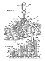
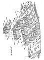
- a toy construction set illustrating our invention has been denoted generally by the reference numeral 10 in Figures 1 and 2. Even though a limited number of blocks have been pictured in Figures I and 2, nonetheless it is believed that a sufficient variety of blocks has been shown so as to provide an understanding of our invention. More specifically, it will be appreciated that a relatively simple geometrical configuration has been selected for the purpose of illustrating our invention in Figures 1 and 2. A far greater number of blocks than those depicted in Figures 1 and 2 would normally constitute a commercial toy construction set when utilizing the teachings of our invention. The actual number of blocks is unimportant to an appreciation of the invention; instead, it is the versatile manner in which the various sizes can be interconnected to each other and to a base plate.
- the base plate 12 which can be fabricated from a suitable plastic, includes a flat panel 14 and downwardly depending side walls 16 forming a space or void 18 in conjunction with a flat surface 20, such as an ordinary table top or floor.
- the panel 14 is formed with a relatively large number of generally circular openings 22, each opening 22 having associated therewith integral lugs or ears 24 which are diametrically located opposite each other and which are integral with the panel 14.
- the toy construction set 10 in practice comprises a relatively large number of blocks, particularly a large number of blocks 30 now to be described, only a limited number of such blocks 30 have been depicted.
- These blocks 30 are of identical construction.
- the three-dimensional configuration shown in Figures 1 and 2 is quite arbitrary and does not represent any pattern that would have meaning to the child; in other words, the general pattern shown in Figures 1 and 2 is rather abstract, but does serve to illustrate the invention.
- a more concrete utilization of the blocks appears in Figure 17, referred to in greater detail hereinafter. Playing an important role as far as the array of blocks appearing in Figures 1 and 2 is concerned would be the vertical arrangement involving the blocks 30.
- the tops of the blocks 30 have been indicated by the reference numeral 32 and have a number of bumps or projections 34 which function to angularly align or register one block 30 with another block 30 therebeneath (best understood from Figure 4).
- the bottoms of the blocks 30 have been denoted by the reference numeral 36 and it should be observed that a number of recesses or cavities 38 extend upwardly from the bottom 36 (also illustrated in Figure 4). Actually, the shape of the recesses 38 complements the shape of the projections 34.
- Each block 30 is formed with generally parallel side walls 40 and generally parallel end walls 42. It will be appreciated that the walls 40 (and the walls 42) are not truly parallel, being slightly tapered because of the draft needed when molding the blocks 30.
- each groove 43 In each of the side walls 40 and in each of the end walls 42 is an undercut groove 43, each groove 43 possessing a truncated appearance. It will be noted that each groove 43 has a slot 44 associated therewith.
- various angles, hitches, quarter rounds, rafters, corner bricks or blocks, hinges and pivot bases have one or more longitudinal tongues or dovetails jutting therefrom.
- the tongue or dovetail generally complements the cross section of the groove 43. In this way, such a tongue or dovetail when slidably received in a groove 43 can laterally connect two blocks 30 together or to another construction set member (not shown).
- the tongue or dovetail and groove arrangement is conventional, forming no part of our invention.
- a tubular bushing or cylindrical wall 46 Depending upon the size of the block 30, and for the sake of discussion it will be assumed that this is a double block, there would be two tubular bushings 46 contained therein.
- Each tubular bushing 46 has a cylindrical bore 48 extending therethrough, the bushing 46 in each instance having an upper opening corresponding to the openings 22 in the base plate 12. It will be observed that there are two diametrically opposite coupling lugs or ears 50 located at the upper end of the tubular bushing 46, that is, at the top 32 of the block 30. Still further, there are two arcuate retaining flanges or shoulders 52 formed integrally within each tubular bushing 46.
- the arcuate retaining flanges or shoulders 52 are located above the bottom 36 of the block 30, there being an integral beveled wall 53 extending upwardly to the flange or shoulder 52 in each instance.
- Figure 11 aptly portrays the relationship between the upper lugs or ears 50 and the lower retaining flanges or shoulders 52.
- the purpose of the lugs 50 and the flanges or shoulders 52 will become manifest as the description progresses. At this time, it is only necessary to recognize that the flanges or shoulders 52 are recessed upwardly or inwardly within the bore 48 (being at the upper end of the beveled walls 53), whereas the lugs 50 are located at the upper end of the bore 48.
- the coupling cam 54 which is clearly shown in Figures 11 and 13 - 16.
- the coupling cam 54 which is of suitable plastic material such as polyoxymethylene (acetal), in each instance includes a generally cylindrical body 56.
- a pair of flanges 58 At the lower end of the body 56, as viewed in Figures 11 and 15, and to some extent in Figure 16, are a pair of flanges 58, the flanges extending diametrically in opposite directions.
- Each flange 58 has formed on its upper side a sloping cam surface 60 formed with a depression or notch at 61, the contour of the cam surface 60, together with the depression or notch 61, being best understood from Figure 15.
- flanges 62 At the upper end of the body 56 of each cam 54 are flanges 62 which extend at right angles with respect to the lower flanges 58, although at different elevations.
- the flanges 62 have beveled edges 63.
- Each cam 54 has formed therein a slot 64a extending downwardly from its upper end, the slot 64a performing a dual purpose.
- the slot 64a provides a recess into which the blade of a tool can be inserted so that the cam 54 can be rotated or twisted when fastening two blocks 30 to each other, and secondly the slot 64a permits the flexing together during assembly at the factory of what amounts to a pair of legs 65 forming the generally cylindrical body 56, the beveled wall 53 acting to cam the legs 65 toward each other during the upward insertion of the cam 54 into the bore 48; stated somewhat differently, the upper end of the slot 64a becomes narrower during this assembly step.
- Each cam 54 also is formed with a second slot 64b extending upwardly from its lower end, the slots 64a and 64b being at 90° relative to each other. It should be mentioned that when an excessive amount of force is applied to a block 30 when coupled to another block 30 by means of a cam 54, an override function is performed in that the slot 64b will become sufficiently narrower so that the two blocks 30 (or whatever number is subjected to the overload) will separate by virtue of the flanges 58 being forced closer together. Additional description of the coupling cam 54, particularly the role played thereby, is perhaps better reserved for later discussion.
- Our toy construction set 10 additionally includes a hand tool 300 having a handle 302 and an integral blade 304.
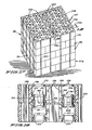
- the base plate 12 is of comparatively simple construction and is presented solely as an illustration of what could be provided in a basic construction set 10. In practice, a more versatile base plate 112 is included in the set 10. As can be perceived from Figures 17 and 18, the more elaborate base plate 112 is employed as the roof of a building utilizing a plurality of blocks 30 interconnected in a wall-like fashion by means of the coupling cams 54 contained therein. While the relatively simple base plate 12, which is illustrative only, underlies the blocks 30, it will be appreciated that the more versatile second base plate 112 would be supplied in lieu of the base plate 12.
- the base plate 112 Describing the base plate 112 in greater detail, it is to be observed that it includes a flat panel 114 having downwardly depending side walls 116. As with the base plate 12, the base plate 112 is provided with a number of generally circular openings 122, each opening 122 having associated therewith integral lugs or ears 124.
- the base plate 112 includes a number of coupling cams 54.
- Two such cams 54 appear in Figure 18, each being disposed in a tubular bushing or cylindrical wall 146 having a cylindrical bore 148. Within the cylindrical wall 146, in each instance, is a flange or shoulder 152 and a beveled wall 153.
- the cam 54 at the left in Figure 18 is depicted in an uncoupled condition, whereas the cam 54 at the right is shown coupled, having been pushed downwardly and twisted through 90° by means of the tool 300 (not illustrated in this figure but shown in Figure 1 as previously mentioned).
- the base plate 112 (used as a roof in Figure 17) contains only peripherally located cams 54.
- the base plate 212 (used as a foundation in Figure 17) also contains only peripherally located cams 54. It will be noted that the base plate 212 includes a flat panel 214 having downwardly depending side walls 216. As with the base plates 12 and 112, the base plate 212 is provided with a number of generally circular openings 222, each opening 222 having associated therewith integral lugs or ears 224.
- the base plate 212 includes a number of peripherally located coupling cams 54.
- the sectional line 21 - 21 is through two peripherally located openings 222.
- Each cam 54 is disposed in a tubular bushing or cylindrical wall 246 having a cylindrical bore 248. Within the cylindrical wall 246, in each instance, is a flange or shoulder 252 and a beveled wall 253.
- the slot 64a permits the body 56 to flex together by reason of the beveled wall 53 (or 153, 253) so as to allow the upper flanges 62, facilitated by the beveled edges 63, to pass by the flanges 52.
- the coupling cam 54 cannot move completely upwardly (downwardly when the block 30 is inverted) and out of the tubular bushing 46 (or 146, 246) because of the interference of the cam flange 58 with the inwardly extending flange 52 and the lugs or ears 5 0 (or 124, 224).
- each of the coupling cams 54 is held captive within its particular cylindrical bore 48 (or 148, 248) by virtue of the lugs 50 (or 124, 224) at the top 32 and the flanges 52 at the bottom 36.
- the coupling cam 54 is both freely rotatable and vertically movable (to a limited extent) within its associated tubular bushing 46 (or 146, 246), once it has been inserted in the manner described above.
- the cam 54 is shiftable axially between the upper lugs 50 (or 124, 224) and the lower flanges 52. It is when the flanges 62, which constitute what might be termed a head on the body 56 of the cam 54, bear against the upper surfaces of the retaining flanges 52 (or 152, 252) that the lower end of the coupling cam 54 projects beneath the bottom 36 (or beneath the plate 112, 212), doing so to the extent that the flanges 58 having the cam surfaces 60 thereon are positioned beneath the lugs or ears 50 (or 124, 224) of the particular block 30 beneath the block 30 that is to be mated therewith.
- the lugs or ears 50 then reside in the depressions or notches 61.
- the cam 54 is twisted through 90° by means of the hand tool 300, then the cam surfaces 60 are angularly oriented in an obstructive relation with the lugs or ears 50 of the block 30 immediately below.
- the notches 61 serve as detents to maintain a releasable engagement and proper alignment with the lugs 50.
- the notches 61 are relatively shallow and their sloping edges permit an override to occur whenever sufficient torque is applied to the hand tool.
- the recesses 38 are dimensioned so as to receive the projections 34 therein, and due to the symmetry thereof, it should be readily apparent that the child has a choice of angles when connecting two blocks 30 together; they can be at 90 0 or at 180°.
- each coupling cam 54 permits the cam 54 to remain completely within the tubular bushing 46. This happens by a slight amount of friction or if a particular block 30 is placed on a flat surface, such as that labeled 20, then the cam 54 if projecting downwardly is urged upwardly into a recessed relationship within the particular cylindrical bore 48, all as clearly evident from the right side of Figure 11.
- the blade 304 of the tool 300 is tapered, the degree of taper being sufficient to provide a slight wedging action and resulting frictional retention of the blade 304 in the slot 64a so that the particular cam 54 can be readily retracted upwardly from, for example, the position at the left in Figure 11 to the position at the right in this figure or from the position at the right in Figure 18 to the position at the left in this latter figure.
- the tool 300 can readily be pulled upwardly to dislodge the blade 304 from its frictional engagement with the cam 54.
- the flanges 58 on the coupling cams 54 can pass upwardly to effect a release or detachment from the base plate 12 or 212 (or the base plate 112 from the blocks 30 therebeneath), the notch 64b under these conditions also narrowing so that the flanges 58 readily move by the inwardly directed lugs or ears 24 (or 124, 224) in effecting a release under a sufficiently excessive load.
- the various blocks 30 can be assembled in various three-dimensional configurations, either on any of the base plates 12, 112 or 212, or under either of the base plates 112 or 212, or on a flat surface, such as that labeled 20. It is preferable, though, to utilize the base plate 12, 112 or 212 which can be provided in various sizes, depending upon the size and complexity of the construction set 10. It will be appreciated that the geometrical shapes can be in the form of a building, a bridge, a vehicle and many other shapes with which a child would be familiar.
- the present invention reduces the shortcomings of the prior art toy construction sets with. respect to vertically assembling and disassembling toy blocks.
- the invention in its preferred form provides a specified means for vertically interconnecting and disconnecting toy blocks, yet permitting various means to be selected and incorporated into the design of the toy blocks, as far as laterally or horizontally connecting the blocks to each other.
Landscapes
- Toys (AREA)
Applications Claiming Priority (2)
| Application Number | Priority Date | Filing Date | Title |
|---|---|---|---|
| US613842 | 1984-05-24 | ||
| US06/613,842 US4551110A (en) | 1984-05-24 | 1984-05-24 | Rotatable cam for use in a toy construction set |
Publications (2)
| Publication Number | Publication Date |
|---|---|
| EP0162730A2 true EP0162730A2 (fr) | 1985-11-27 |
| EP0162730A3 EP0162730A3 (en) | 1987-06-10 |
Family
ID=24458891
Family Applications (1)
| Application Number | Title | Priority Date | Filing Date |
|---|---|---|---|
| EP85303705A Withdrawn EP0162730A3 (en) | 1984-05-24 | 1985-05-24 | Toy construction set |
Country Status (10)
| Country | Link |
|---|---|
| US (1) | US4551110A (fr) |
| EP (1) | EP0162730A3 (fr) |
| JP (1) | JPS60256481A (fr) |
| AU (1) | AU4281785A (fr) |
| BR (1) | BR8502403A (fr) |
| DK (1) | DK216385A (fr) |
| ES (1) | ES8702798A1 (fr) |
| FI (1) | FI852044A7 (fr) |
| NO (1) | NO852050L (fr) |
| ZA (1) | ZA853761B (fr) |
Cited By (5)
| Publication number | Priority date | Publication date | Assignee | Title |
|---|---|---|---|---|
| EP0542007A1 (fr) * | 1991-11-14 | 1993-05-19 | Grässlin Kg | Dispositif de liaison de profilés de construction et/ou de pièces semblable, spécialement pour des systèmes d'assemblage flexibles |
| NL1002070C2 (nl) * | 1996-01-11 | 1997-07-14 | Wild Design Holding Gmbh | Modulair bouwsysteem. |
| NL1006524C2 (nl) * | 1997-07-10 | 1999-01-12 | Wild Design Holding Gmbh | Modulair bouwsysteem. |
| NL1007436C2 (nl) * | 1997-11-04 | 1999-05-06 | Wild Design Holding Gmbh | Modulair bouwsysteem met draaikoppeling. |
| CN106999782A (zh) * | 2015-11-24 | 2017-08-01 | 普罗博有限公司 | 组装式拼块 |
Families Citing this family (58)
| Publication number | Priority date | Publication date | Assignee | Title |
|---|---|---|---|---|
| NL8503134A (nl) * | 1985-11-14 | 1987-06-01 | Cornelia Petronella Maria West | Bouwelement, alsmede koppelpen voor het verbinden van op elkaar geplaatste bouwelementen. |
| US4813903A (en) * | 1986-09-23 | 1989-03-21 | Tomy Kogyo Co., Inc. | Block toy with integral drive shaft |
| DE8810282U1 (de) * | 1987-10-08 | 1989-03-23 | Vivaria GmbH, Import von Pflanzen und Tieren, 8192 Geretsried | Durchbrochener Pflanzenbehälter für Epiphyten |
| DE3809922A1 (de) * | 1988-03-24 | 1989-10-05 | Fischer Artur Werke Gmbh | Spielbauelement mit einem verbindungszapfen |
| US5322466A (en) * | 1989-02-24 | 1994-06-21 | Interlego A.G. | Detachable connecting device for toy-construction elements |
| DK168194B1 (da) * | 1991-11-06 | 1994-02-28 | Lego As | En skrue til et legetøjsbyggesæt |
| USD341172S (en) | 1991-11-06 | 1993-11-09 | Interlego A.G. | Toy tool |
| AU2938192A (en) * | 1991-11-25 | 1993-06-28 | Paul Thomas Maddock | Toy building blocks |
| USD344300S (en) | 1992-11-24 | 1994-02-15 | Interlego A.G. | Element for a toy building set |
| USD352750S (en) | 1993-09-22 | 1994-11-22 | Interlego A.G. | Building plate for a toy building set |
| US5454746A (en) * | 1994-01-06 | 1995-10-03 | Meccano, S.A. | Toy hand tool |
| US5816882A (en) * | 1994-01-06 | 1998-10-06 | Meccano, S.A. | Construction toy kit |
| AU122555S (en) * | 1994-01-06 | 1995-02-07 | Meccano | Toy corner brace |
| USD374466S (en) | 1994-06-02 | 1996-10-08 | Meccano S.A. | Figurine shaped screwdriver for toys |
| DE19501742A1 (de) * | 1995-01-23 | 1996-07-25 | Brandstaetter Geobra | Bauelemente-Spielsystem |
| US5599512A (en) * | 1995-05-10 | 1997-02-04 | Poly Vac, Incorporated | Sterilization support and storage container system |
| US5664387A (en) * | 1996-06-24 | 1997-09-09 | Bhatti; Khaqan | Modular block construction system |
| USD385926S (en) * | 1996-09-17 | 1997-11-04 | Interlego Ag | Toy building element |
| US5826394A (en) * | 1996-11-19 | 1998-10-27 | Rokenbok Toy Company | Basic building blocks for constructing complex building structure |
| US5820436A (en) * | 1997-02-07 | 1998-10-13 | Mattel, Inc. | Carrying case with apertured lid for mounting models constructed of building systems components |
| USD425138S (en) * | 1998-02-27 | 2000-05-16 | Haddad Haitham N | Modular, reconfigurable educational sculpture |
| US6250986B1 (en) | 1999-02-08 | 2001-06-26 | Soren Christian Sorensen | Building element for set of toy building blocks |
| DE10049218C2 (de) * | 2000-09-28 | 2003-01-02 | Phoenix Contact Gmbh & Co | Elektronikgehäusesystem |
| EP1464369A1 (fr) * | 2003-04-04 | 2004-10-06 | Theodorus Suibertus Anthonius ROLF | Bloc démontable pour jeu de construction, vis associée et tournevis |
| US20050249547A1 (en) * | 2004-05-10 | 2005-11-10 | Chang Chen C | Combinable wooden block |
| DE102004024395A1 (de) * | 2004-05-17 | 2005-12-08 | Bruder Spielwaren Gmbh & Co. Kg | Bausystem |
| US7140612B2 (en) * | 2004-08-16 | 2006-11-28 | Wisonet, Inc. | Cubic assembly puzzle and support structure |
| US20080160875A1 (en) * | 2005-08-15 | 2008-07-03 | Boaz Leicht | Interconnectible Building Elements For Intellectual Challenge Games |
| US7736211B2 (en) * | 2005-11-29 | 2010-06-15 | Minds-I, Inc. | Construction system |
| US7517270B2 (en) * | 2006-05-30 | 2009-04-14 | Minds-I, Inc. | Construction system |
| US20080075528A1 (en) * | 2006-09-22 | 2008-03-27 | Michael Marzetta | Construction system |
| US20090017716A1 (en) * | 2007-07-11 | 2009-01-15 | Michael Marzetta | Construction system |
| US7841923B2 (en) * | 2007-11-13 | 2010-11-30 | Minds-I, Inc. | Vehicle axle joint for a toy vehicle |
| US8540545B2 (en) * | 2010-02-06 | 2013-09-24 | Boaz Leicht | Interconnectible building elements for intellectual challenge games |
| DE102009016633A1 (de) * | 2008-11-26 | 2010-05-27 | Illinois Tool Works Inc., Glenview | Befestigungsmittel zur Vormontage eines stiftförmigen Verbindungsmittels in einer Durchgangsöffnung eines Bauteils |
| US9126086B2 (en) * | 2010-09-17 | 2015-09-08 | II Hershel James HOWARD | Sports training system and method |
| US9573074B2 (en) | 2010-10-21 | 2017-02-21 | Lego A/S | Toy building set |
| KR102070710B1 (ko) | 2010-10-21 | 2020-01-29 | 레고 에이/에스 | 장난감 조립 세트 |
| US9010059B2 (en) * | 2011-01-31 | 2015-04-21 | Value Chain Network (Hong Kong) Limited | Building blocks and building block fasteners |
| ES2731128T3 (es) * | 2012-10-31 | 2019-11-14 | William R Chesser | Productos de construcción modular y método de ensamblaje de los mismos |
| US8905812B2 (en) * | 2013-02-11 | 2014-12-09 | Cheng Pai-Chen | Toy block |
| US9498703B2 (en) * | 2013-03-13 | 2016-11-22 | Stat Ventures, Inc. | Assembly kit for three dimensional works |
| TWI517886B (zh) * | 2014-11-03 | 2016-01-21 | Genius Toy Taiwan Co Ltd | Clamped buckle groups and combinations thereof |
| US9839860B2 (en) * | 2015-05-12 | 2017-12-12 | Saturn Enterprises, Inc. | Interlocking construction toy |
| US10106980B2 (en) * | 2016-04-16 | 2018-10-23 | Lazaro A. Martinez | Block interlocking module and system to build architectural structures |
| CN107982937B (zh) * | 2018-01-02 | 2019-05-31 | 东莞市微石塑胶金属科技有限公司 | 拼接结构件 |
| US11059559B2 (en) | 2018-03-05 | 2021-07-13 | General Electric Company | Acoustic liners with oblique cellular structures |
| US11047304B2 (en) | 2018-08-08 | 2021-06-29 | General Electric Company | Acoustic cores with sound-attenuating protuberances |
| US10823059B2 (en) | 2018-10-03 | 2020-11-03 | General Electric Company | Acoustic core assemblies with mechanically joined acoustic core segments, and methods of mechanically joining acoustic core segments |
| USD902307S1 (en) * | 2018-12-11 | 2020-11-17 | Worakorn Phongsuwan | Block pencil holder |
| US11434819B2 (en) | 2019-03-29 | 2022-09-06 | General Electric Company | Acoustic liners with enhanced acoustic absorption and reduced drag characteristics |
| IT202000007156A1 (it) * | 2020-04-03 | 2021-10-03 | Fulvio Monteverde | Elemento di costruzione giocattolo e set di costruzione giocattolo |
| US11668236B2 (en) | 2020-07-24 | 2023-06-06 | General Electric Company | Acoustic liners with low-frequency sound wave attenuating features |
| US11970992B2 (en) | 2021-06-03 | 2024-04-30 | General Electric Company | Acoustic cores and tools and methods for forming the same |
| US12142253B2 (en) | 2021-10-05 | 2024-11-12 | General Electric Company | Solid adhesive film for acoustic liner and method |
| US20230294010A1 (en) * | 2022-03-18 | 2023-09-21 | Troy Hyde | Portable Activity Board Device |
| US11965425B2 (en) | 2022-05-31 | 2024-04-23 | General Electric Company | Airfoil for a turbofan engine |
| US12312969B2 (en) | 2023-01-17 | 2025-05-27 | General Electric Company | Airfoils for turbofan engines |
Family Cites Families (10)
| Publication number | Priority date | Publication date | Assignee | Title |
|---|---|---|---|---|
| DE7416385U (fr) * | 1974-11-14 | Richard Friedrich | ||
| US1680289A (en) * | 1924-08-16 | 1928-08-14 | Auto Tool & Gauge Company | Hair-clipping device |
| FR999876A (fr) * | 1946-01-22 | 1952-02-05 | Jeu | |
| US2885822A (en) * | 1956-06-29 | 1959-05-12 | Richard A Onanian | Construction set |
| US3195266A (en) * | 1962-05-07 | 1965-07-20 | Richard A Onanian | Construction toy comprising blocks and coupling means |
| US3220078A (en) * | 1963-08-08 | 1965-11-30 | Elastic Stop Nut Corp | Rotary fastener |
| US3659376A (en) * | 1969-05-30 | 1972-05-02 | Artur Fischer | Connecting arrangement for use in a toy assembly kit |
| JPS523567Y2 (fr) * | 1974-03-30 | 1977-01-25 | ||
| DE2710392A1 (de) * | 1977-03-10 | 1978-09-14 | Fischer Artur Dr H C | Traeger fuer spielmodelle |
| US4281895A (en) * | 1979-04-12 | 1981-08-04 | Quantor Corporation | Quick change lens mount |
-
1984
- 1984-05-24 US US06/613,842 patent/US4551110A/en not_active Expired - Lifetime
-
1985
- 1985-05-15 DK DK216385A patent/DK216385A/da not_active Application Discontinuation
- 1985-05-17 ZA ZA853761A patent/ZA853761B/xx unknown
- 1985-05-21 BR BR8502403A patent/BR8502403A/pt unknown
- 1985-05-22 FI FI852044A patent/FI852044A7/fi not_active Application Discontinuation
- 1985-05-22 NO NO852050A patent/NO852050L/no unknown
- 1985-05-23 ES ES543425A patent/ES8702798A1/es not_active Expired
- 1985-05-23 AU AU42817/85A patent/AU4281785A/en not_active Abandoned
- 1985-05-24 EP EP85303705A patent/EP0162730A3/en not_active Withdrawn
- 1985-05-24 JP JP60111981A patent/JPS60256481A/ja active Pending
Cited By (10)
| Publication number | Priority date | Publication date | Assignee | Title |
|---|---|---|---|---|
| EP0542007A1 (fr) * | 1991-11-14 | 1993-05-19 | Grässlin Kg | Dispositif de liaison de profilés de construction et/ou de pièces semblable, spécialement pour des systèmes d'assemblage flexibles |
| NL1002070C2 (nl) * | 1996-01-11 | 1997-07-14 | Wild Design Holding Gmbh | Modulair bouwsysteem. |
| WO1997025121A1 (fr) * | 1996-01-11 | 1997-07-17 | Wild-Design Holding Gmbh | Systeme de construction modulaire |
| NL1006524C2 (nl) * | 1997-07-10 | 1999-01-12 | Wild Design Holding Gmbh | Modulair bouwsysteem. |
| WO1999002234A1 (fr) * | 1997-07-10 | 1999-01-21 | Wild-Design Holding Gmbh | Systeme de construction modulaire |
| NL1007436C2 (nl) * | 1997-11-04 | 1999-05-06 | Wild Design Holding Gmbh | Modulair bouwsysteem met draaikoppeling. |
| WO1999022834A1 (fr) * | 1997-11-04 | 1999-05-14 | Wild-Design Holding Gmbh | Systeme de construction modulaire avec couplage rotatif |
| US6595825B1 (en) | 1997-11-04 | 2003-07-22 | Wild-Design Holding Gmbh | Modular construction system with rotating coupling |
| CN106999782A (zh) * | 2015-11-24 | 2017-08-01 | 普罗博有限公司 | 组装式拼块 |
| CN106999782B (zh) * | 2015-11-24 | 2019-11-08 | 普罗博有限公司 | 组装式拼块 |
Also Published As
| Publication number | Publication date |
|---|---|
| FI852044L (fi) | 1985-11-25 |
| BR8502403A (pt) | 1986-01-21 |
| FI852044A0 (fi) | 1985-05-22 |
| ZA853761B (en) | 1986-12-30 |
| FI852044A7 (fi) | 1985-11-25 |
| EP0162730A3 (en) | 1987-06-10 |
| NO852050L (no) | 1985-11-25 |
| DK216385A (da) | 1985-11-25 |
| DK216385D0 (da) | 1985-05-15 |
| ES8702798A1 (es) | 1987-01-16 |
| JPS60256481A (ja) | 1985-12-18 |
| AU4281785A (en) | 1985-11-28 |
| US4551110A (en) | 1985-11-05 |
| ES543425A0 (es) | 1987-01-16 |
Similar Documents
| Publication | Publication Date | Title |
|---|---|---|
| US4551110A (en) | Rotatable cam for use in a toy construction set | |
| EP0379389B1 (fr) | Bloc de construction | |
| US6648715B2 (en) | Snap-fit construction system | |
| US5405080A (en) | Toy track coupling mechanism | |
| EP0375544B1 (fr) | Ensemble de jeux de construction | |
| CA2359308C (fr) | Element de construction pour ensemble jeu de construction | |
| US6050044A (en) | Building block | |
| CA2087144A1 (fr) | Jeu de cubes interverrouillables permettant la construction de structures flexibles | |
| EP0228103B1 (fr) | Blocs de construction à superposer les uns sur les autres et broche d'assemblage des blocs | |
| US5826394A (en) | Basic building blocks for constructing complex building structure | |
| US4629192A (en) | Interlocking puzzle blocks | |
| EP0494917B1 (fr) | Kit de construction de jouets | |
| EP0891797A1 (fr) | Eléments de jeu de construction | |
| US5503330A (en) | Track bed simulating assembly for snap together model railroad tracks | |
| WO1986003133A1 (fr) | Base de constructions pour les composants d'un jeu de constructions | |
| JP2014516728A (ja) | ビルディングブロック | |
| EP0464065B1 (fr) | Outil de separation d'elements dans un ensemble de construction | |
| US3224135A (en) | Construction set including members with plural connecting means | |
| US4894963A (en) | Building kit | |
| CA2337238A1 (fr) | Bloc de construction | |
| WO2008078942A1 (fr) | Jeu de construction à angle variable | |
| US6554678B2 (en) | Sculptural toy | |
| US5458495A (en) | Building block having opposing male and female hinge elements for connection to like elements on another like block | |
| CA1286872C (fr) | Dispositif pour le raccordement separable de deux pieces prefabriquees | |
| EP0149689A1 (fr) | Elément de construction modulaire en particulier pour la réalisation de cloisons et ouvrages analogues |
Legal Events
| Date | Code | Title | Description |
|---|---|---|---|
| PUAI | Public reference made under article 153(3) epc to a published international application that has entered the european phase |
Free format text: ORIGINAL CODE: 0009012 |
|
| AK | Designated contracting states |
Designated state(s): AT BE CH DE FR GB IT LI LU NL SE |
|
| PUAL | Search report despatched |
Free format text: ORIGINAL CODE: 0009013 |
|
| AK | Designated contracting states |
Kind code of ref document: A3 Designated state(s): AT BE CH DE FR GB IT LI LU NL SE |
|
| STAA | Information on the status of an ep patent application or granted ep patent |
Free format text: STATUS: THE APPLICATION IS DEEMED TO BE WITHDRAWN |
|
| 18D | Application deemed to be withdrawn |
Effective date: 19871202 |
|
| RIN1 | Information on inventor provided before grant (corrected) |
Inventor name: SELVAGE, CRAIG C. Inventor name: VENTURA, FRANK D. |