EP0162940A1 - Interrupteur de protection contre les surchages - Google Patents
Interrupteur de protection contre les surchages Download PDFInfo
- Publication number
- EP0162940A1 EP0162940A1 EP84106193A EP84106193A EP0162940A1 EP 0162940 A1 EP0162940 A1 EP 0162940A1 EP 84106193 A EP84106193 A EP 84106193A EP 84106193 A EP84106193 A EP 84106193A EP 0162940 A1 EP0162940 A1 EP 0162940A1
- Authority
- EP
- European Patent Office
- Prior art keywords
- housing
- contact
- switch according
- heating resistor
- safety switch
- Prior art date
- Legal status (The legal status is an assumption and is not a legal conclusion. Google has not performed a legal analysis and makes no representation as to the accuracy of the status listed.)
- Granted
Links
- 238000010438 heat treatment Methods 0.000 claims abstract description 46
- 230000000295 complement effect Effects 0.000 claims description 4
- 238000005476 soldering Methods 0.000 claims description 2
- 229910000679 solder Inorganic materials 0.000 abstract 1
- 238000013461 design Methods 0.000 description 5
- 239000004020 conductor Substances 0.000 description 4
- 238000004049 embossing Methods 0.000 description 3
- 238000004519 manufacturing process Methods 0.000 description 3
- 238000011161 development Methods 0.000 description 2
- 230000018109 developmental process Effects 0.000 description 2
- 239000000463 material Substances 0.000 description 2
- 238000013021 overheating Methods 0.000 description 2
- 125000006850 spacer group Chemical group 0.000 description 2
- 238000012546 transfer Methods 0.000 description 2
- 238000004873 anchoring Methods 0.000 description 1
- 238000013459 approach Methods 0.000 description 1
- 239000000969 carrier Substances 0.000 description 1
- 239000011248 coating agent Substances 0.000 description 1
- 238000000576 coating method Methods 0.000 description 1
- 238000010276 construction Methods 0.000 description 1
- 230000001419 dependent effect Effects 0.000 description 1
- 230000000694 effects Effects 0.000 description 1
- 238000005516 engineering process Methods 0.000 description 1
- 238000007373 indentation Methods 0.000 description 1
- 238000003780 insertion Methods 0.000 description 1
- 230000037431 insertion Effects 0.000 description 1
- 239000002932 luster Substances 0.000 description 1
- 230000007257 malfunction Effects 0.000 description 1
- 238000012544 monitoring process Methods 0.000 description 1
- TWNQGVIAIRXVLR-UHFFFAOYSA-N oxo(oxoalumanyloxy)alumane Chemical compound O=[Al]O[Al]=O TWNQGVIAIRXVLR-UHFFFAOYSA-N 0.000 description 1
- 230000001681 protective effect Effects 0.000 description 1
- 230000005855 radiation Effects 0.000 description 1
- 229910052709 silver Inorganic materials 0.000 description 1
- 239000004332 silver Substances 0.000 description 1
- 239000007787 solid Substances 0.000 description 1
- 239000011343 solid material Substances 0.000 description 1
- 230000007704 transition Effects 0.000 description 1
Images

Classifications
-
- H—ELECTRICITY
- H01—ELECTRIC ELEMENTS
- H01H—ELECTRIC SWITCHES; RELAYS; SELECTORS; EMERGENCY PROTECTIVE DEVICES
- H01H1/00—Contacts
- H01H1/50—Means for increasing contact pressure, preventing vibration of contacts, holding contacts together after engagement, or biasing contacts to the open position
- H01H1/504—Means for increasing contact pressure, preventing vibration of contacts, holding contacts together after engagement, or biasing contacts to the open position by thermal means
-
- H—ELECTRICITY
- H01—ELECTRIC ELEMENTS
- H01H—ELECTRIC SWITCHES; RELAYS; SELECTORS; EMERGENCY PROTECTIVE DEVICES
- H01H37/00—Thermally-actuated switches
- H01H37/02—Details
- H01H37/32—Thermally-sensitive members
- H01H37/52—Thermally-sensitive members actuated due to deflection of bimetallic element
- H01H37/54—Thermally-sensitive members actuated due to deflection of bimetallic element wherein the bimetallic element is inherently snap acting
- H01H37/5427—Thermally-sensitive members actuated due to deflection of bimetallic element wherein the bimetallic element is inherently snap acting encapsulated in sealed miniaturised housing
Definitions
- the invention relates to an electrical overload protection switch according to the preamble of claim 1.
- overload protection switches are known in principle. They serve to protect electrical consumers against overheating and can be used for a wide variety of electrical devices. Special areas of application are in cable drums, electrical distributors and sometimes also in cables for the supply of electrical appliances.
- the overload protection switch with its switch contacts is in the circuit of the consumer to be monitored. A strong temperature increase at the monitoring location is assumed as an indication of the existence of an overload condition. and when a limit temperature is exceeded, the switch contacts are electrically isolated by means of a bimetal switch. The direct power supply to the consumer via the switch contacts is thus interrupted and permanent damage to the building caused by excessive temperatures is prevented.
- the open state of the bimetallic switch should now be maintained until there is no longer any fear of the consumer being automatically switched on again; in particular, an operator is to be caused to disconnect the consumer from the supply network before the overload protection switch returns to its normal state and a current flow through the switch contacts enabled again.
- the heating resistor connected in parallel to the bimetal switch is used for this.
- the heating resistor is practically bridged when the bimetal switch is closed, so that it experiences no or at most minimal heating.
- the bimetal switch opens the current flow to the consumer takes place exclusively via the heating resistor. This is designed so high-resistance that the supply voltage drops to a large extent on the heating resistor, and the remaining small voltage drop at the consumer can not lead to an operational malfunction of the latter.
- the heating resistor heats up so strongly in a short time that the bimetal switch remains in the overheated, open position assigned to an interruption of the switching contacts.
- the current flow through the heating resistor must be interrupted, which can be done by switching off the consumer or pulling the power plug. Briefly switching off the consumer is not sufficient to restore the normal condition of the overload protection, since the unit first has to cool down, which takes a certain period of time due to the predetermined thermal inertia.
- overload safety switches working according to the principle described are associated with high production costs with regard to various individual parts, and in particular the bimetal switch. They also have the disadvantage of being cumbersome and complicated, and they require a considerable amount of work in the assembly. For these reasons, overload protection switches of the type mentioned have not been widely used in practice.
- the object of the invention is to remedy these disadvantages and to provide an overload protection switch which is distinguished by a particularly simple construction and can be produced and assembled with little effort.
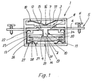
- the overload protection switch has a housing 1 which contains a temperature-dependent switching circuit breaker which protects a connected consumer from overheating.
- a bimetal switch is primarily considered as a circuit breaker. This receives a piece of bimetal 2, which undergoes thermal deformation, as a result of which switching contacts 3 are electrically connected to one another or separated from one another.
- Contact lugs 4 are provided as carriers of the switching contacts 3 and are captively attached to the housing 1. One end 5 of the contact lugs 4 protrudes from the housing 1. It is used to connect the electrical supply line that leads to the consumer to be secured.
- a contact lug 4 is connected to a network conductor and the other contact lug 4 to a conductor leading to the consumer, for which purpose suitable cable fastening means are provided at the ends 5.
- two clamping screws 6 are indicated in FIG. 1, which press a stripped cable end against the contact tabs 4.
- other devices for the preferably solderless connection can also be used, e.g. in the form of commercially available luster terminals.
- the other end of the contact lugs 4 protrude into the housing 1, where they come to lie at the same height from one another. They are interconnected via a contact bridge 7 made of conductive material.
- the contact bridge 7 lies on the surface of the contact lugs 4, and it can be lifted off by deforming the bimetal 2.
- As contact point of contact bridge? serve two dome-shaped contact attachments 8, which are formed on the contact lugs 4, for example by embossing. To achieve a low transition resistance, it is recommended to silver the contact attachments 8.
- the contact bridge? is movably guided in the housing 1 with respect to the contact tabs 4. It is acted upon on one end face by a plunger 9, which establishes a force-transmitting connection to the bimetal piece 2.
- the plunger 9 according to FIG.
- the shaft 10 is stamp-shaped. It has a cylindrical shaft 10 which is guided so that it can move axially in a suitable housing opening 11. At its end facing the contact bridge 7, the shaft 10 is expanded in the form of a protruding stamp plate 12. The stamp plate 12 lies flat against the contact bridge 7. It also forms a stop that limits the insertion depth of the plunger 9 in the direction of the bimetal piece 2. The opposite axial end of the shaft 10 forms a foot with which the plunger 9 stands centrally on the bimetal piece 2.
- the bimetallic piece 2 is held on its edge in a membrane-like manner on the housing 1. It preferably has the shape of a circular disk, and accordingly the housing 1 is provided with a circumferential ring recess 13 which receives the edge of the bimetal piece 2.
- the bimetal piece 2 extends freely through a chamber 14 in the interior of the housing 1, the required play for the thermal deformation of the bimetal piece 2 being ensured.
- Fig. 1 shows the bimetal piece 2 in a curved state away from the contact bridge 7.
- the contact bridge 7 rests on the contact attachments 8, and between the contact lugs 4 there is an electrical connection via the contact bridge? produced; this corresponds to the normal state of the overload protection switch according to the invention, in which the connected one Consumer is loaded with the full mains voltage.
- the bimetal piece 2 heats up, deforming it against the curvature shown in FIG. 1.
- This movement of the contact bridge 7 takes place against the force of a return spring 15, which loads the contact bridge 7 on the end face facing away from the plunger 9
- the return spring 15 is received in a suitable opening in the housing 1. It has a bow-shaped shape and lies with its apex 16 on the contact bridge 7.
- Two symmetrical spring arms 17 extend on both sides of the apex 16 and are curved at their ends Support against a bottom 18 of the housing 1.
- the overload protection switch according to the invention only returns to the normal position if the connected consumer has previously been switched off or otherwise disconnected from the mains.
- This protective effect which prevents an uncontrolled restart of the consumer, is achieved by means of a heating resistor 19 in the interior of the housing 1.
- the heating resistor 19 is electrically connected in parallel with the bimetal switch, and it is thermally coupled to the bimetal piece 2.
- a good heat transfer from the heating resistor 19 to the bimetal piece 2 is shown in the embodiment example ensures that these two components are arranged in one and the same chamber 14 of the housing 1.
- the heating resistor 19 is fixed essentially parallel and at a short distance from the bimetal piece 2 on the housing 1.
- Webs 20 serve as spacers, which limit the ring recess 13 for the bimetallic disc 2 at the bottom.
- the webs 20 only cover the region of the bimetal piece 2 near the edge, and likewise only the edge of the heating resistor 19 is in contact with the webs 20.
- the electrical connection of the heating resistor 19 is carried out on the contact lugs 4.
- a design which is particularly advantageous in terms of assembly technology and saves material is one in which the heating resistor 19 is simultaneously held in the housing 1 by means of two resilient clamping brackets 22 and connected to the contact lugs 4.
- the contact lugs 4 have a second contact point which, like the contact attachments 8, is coated in a suitable manner in order to achieve a low contact resistance, and in particular can be silver-plated.
- the contact point is located on the underside of the contact tabs 4 facing away from the contact attachments 8. While the contact attachments 8 are located in a central region of the housing 1, the contact points for the clamping bracket 22 lie close to the edge of the housing.
- a guide channel 23 is provided on the edge side next to the ring recess 13 for the bimetal piece 2, into which the clamping bracket 22 can be inserted.
- the guide channel 23 and the annular recess 13 are separated from one another by a rib 24 formed integrally on the housing 1.
- the guide channel 23 opens into the contact lugs 4 into a cavity below the connection point for the clamping bracket 22, and on the opposite side the guide channel 23 ends below the heating resistor 19 in the chamber 14 of the housing 1.
- the heating resistor 19 has the shape of a flat, elongated rectangular plate, the lateral edge zones of which are designed for contacting the clamping brackets 22.
- a heating resistor 19 is preferably produced as a thick-film resistor. It consists of an aluminum oxide plate, the edge zones. e.g. coated with AgPd and the central area of which is designed as a resistance surface; the latter can be done, for example, by coating the middle region with a layer of resistance paste.
- this design is not essential for the invention; Rather, a resistance wire or a heating spiral wound from resistance wire can also be used as the heating resistor 19.
- a resistor with a positive temperature coefficient PTC resistor, PTC thermistor
- the serving for connecting the heating resistor 19 clamp brackets 22 are supported against a bottom 25 of the housing 1 and apply spring tension to both the underside of the contact lugs 4 and the underside of the heating resistor 19.
- the clamp brackets 22 consist of an electrically conductive material, so that a electrical connection between the connection points on the contact lugs 4 and the heating resistor 19 is established.
- the spring tension of the clamping bracket 22 ensures a secure contact; at the same time, the clamp brackets 22 also have a mechanical holding function for the heating resistor 19, which they press against the webs 20.
- the clamp bracket 22 have a C-shaped profile. Its C-back is received in the guide channel 23, while its curved C-legs serve to make contact with the contact lug 4 or the heating resistor 19.
- the C-leg coming into contact with the heating resistor 19 is wavy in a serpentine shape, so that there are two contact points 27 with the bottom 25. Between these contact points 27 there is a single contact point 28 of the C-legs 26 on the heating resistor 19, to which a resilient contact pressure is exerted.
- the overload safety switch according to the invention is characterized in that all of its components are received and guided in suitable housing recesses, and that the electrical connections located in the interior of the housing can be made without soldering. This makes the overload protection switch particularly easy to manufacture and assemble.
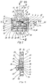
- the housing 1 also consists of two almost identical half-shells, which further simplifies production. A practical embodiment of such a housing is described below with reference to FIGS. 2 to 6, the same parts with the same Reference numerals are provided.
- FIG. 2 the view is directed towards an open half-shell of the housing 1.
- the drawing plane corresponds to the parting plane of the half shells.
- Components of the overload protection switch are inserted into the half-shell, which protrude beyond the parting plane and are held in both half-shells when the housing 1 is closed; these components appear cut in Fig. 2.
- the overload protection switch in turn has two contact lugs 4, of which only the right one is shown in FIG. 2; the left half of FIG. 2, however, shows the slot 29 in the housing 1, which receives the contact lugs 4.
- the shape of the anchoring of the contact lugs 4 in the housing 1 can be seen in FIG. 2, FIG. 3 and in particular FIG. 6.
- the contact lugs 4 have an approximately rectangular plan, and on the side edges 30 two mutually opposite notches 31 are excluded.
- the contact lugs 4 are inserted into the slot 29 of the housing half-shells, the notch 31 coming to lie at the level of the housing edge 32.
- the slots 29 are placed so deep in the solid material of the housing half-shells that a nose 33 remains (see FIG. 3) which falls into the notches 31.
- the contact lugs 4 like the other components of the overload protection switch, are first inserted into a half-shell of the housing, and then the other half-shell of the housing 1 is closed above them.
- the contact lugs 4 are locked in their notches 31 by lugs 33 on both half-shells in the housing 1.
- the end 5 of the contact lugs 4 protruding from the housing 1 is provided with a cable fastening device in the form of two angled prongs 34, which with a clamping screw cooperate in a threaded bore 35.
- the prongs 34 start on trapezoidal beveled front edges of the contact posts 4 and they project downward from the contact plane.
- Other forms of cable attachment are also conceivable.
- the end of the contact lugs 4 in the interior of the housing 1 carries a contact attachment 8 in the form of a dome-shaped configuration; the associated counter-embossing on the opposite underside of the contact lugs 4 is not shown in the figures.
- the contact lugs 4 are held in the half-shells of the housing 1 between molded webs 36, 37.
- the web 37 on the side of the contact attachments 8 also serves as a guide for the contact bridge 7 and as a support for the return spring 15 which acts on the contact bridge 7.
- the contact bridge 7 is rectangular in cross-section and narrower than the contact lugs 4. It is provided on its upper side facing the return spring 15 with a centrally shaped spherical cap 38 which e.g. can be applied by embossing.
- the ball dome 38 serves to center the return spring 15, which is designed in the shape of a bow and rests with its apex 16 on the contact bridge 7.
- the apex 16 is complementary to the ball dome 38 with an indentation in which the ball dome 38 comes to rest in a form-fitting manner.
- the contact bridge 7 and the return spring 15 are thereby aligned and fixed to one another such that a central introduction of force onto the contact bridge 7 is always ensured.
- the width of the return spring 15 corresponds approximately to that of the contact bridge 7.
- Contact bridge 7 and return spring 15 both rest on the web 37, which for this purpose extends in steps on two mutually offset levels in the interior of the housing 1.
- a view from the parting plane of the housing half-shells shows in the background a holding section 39 of the web 37 with which it contacts the contact lugs 4.
- This holding section 39 extends over the full length of the contact lugs 4 towards the center of the housing 1.
- a step 40 which has a trapezoidal profile, projects from the holding section 39 into the foreground of FIG. 2 in steps.
- the end face 41 of the shoulder 40 directed towards the center of the housing 1 forms a lateral stop for the contact bridge 7, which is guided with its transverse sides between the shoulders 40.
- the contact bridge 7 is mounted on the long side between the holding sections 39; for this purpose the contact bridge 7 is narrower than the contact lugs 4.
- the inclined upper side 42 of the shoulder 40 delimits a housing chamber which receives the return spring 15.
- the inclination of the top 42 is matched to the spread angle of the bow-shaped return spring 15. As already mentioned, the latter has approximately the same width as the contact bridge 7. It is therefore held captively between the surface of the holding section 39, the inclined upper side 42 of the shoulder 40 and the bottom 18 of the housing 1.
- a semi-cylindrical recess 43 is provided in the half-shells of the housing 1, which receives a circular bimetallic disc 2.
- the recess 43 is graduated in diameter.
- a section of larger diameter 44 halfway up the recess 43 is axially separated by sections 45 smaller diameter limited.
- the portion of larger diameter 44 takes up the edge of the bimetallic disc 2, and the portions 45 of smaller diameter ensure the movement play required for the thermal deformation.
- the bimetallic disc 2 is in force-transmitting connection with the contact bridge 7 via a plunger 9.
- the plunger 9 is a simple round rod, which is received between semi-cylindrical guide surfaces of the housing half-shells.
- a heating resistor 19 in the form of a rectangular plate is contained in the housing 1.
- the heating resistor 19 is in contact with a rib 24, which serves as a spacer to the bimetallic disc 2. It is locked in this position by means of two resilient clamping brackets 22, which at the same time establish an electrical connection to the contact tabs 4.
- the clamping brackets 22 have the profile of a parallelogram open on a base line, and the bracket ends are rounded in a dome shape.
- the clamp brackets 22 are inserted with their parallelogram back 46 into a guide channel of the housing half-shells, and the parallelogram legs 47 act resiliently on the contact lug 4 or the heating resistor 19, their angle of attack being elastically variable relative to the parallelogram back 46.
- the outer contour of the housing half-shells essentially follows that of the components contained.
- the contact lugs 4, the contact bridge 7, the return spring 15 and the heating resistor 19 have a rectangular plan.
- the corresponding part of the housing half-shells has a cuboid shape.
- the bimetal piece 2 is a circular disk. It is received in a circular cylindrical bulge 48 of the housing half-shells 1.
- tabs 49, 50 are also formed, by means of which the half-shells are assembled when the housing 1 is assembled.
- the tabs 49, 50 form cuboid approaches of the housing half-shells with reduced width and thickness in the illustrated embodiment. They are located above the contact level, or below the heating resistor 19, and are provided with fastening means in the form of two rivet holes 51.
- the tab 49 below the heating resistor 19 is short and solid in the material.
- the other flap 50 is extended upwards and designed as a hollow body, material-shaped web 52 being provided only in the vicinity of the rivet hole 51.
- the half-shells can be provided on their contact surface with complementary guide structures which engage with one another according to the tongue and groove principle and position the half-shells during assembly.
- the housing edge 32 accordingly carries a web 53 with a triangular cross section on one half side of each half shell, and the housing edge 32 on the other half side is provided with a complementary triangular groove 54.
- the web 53 of one half-shell falls into the triangular groove 54 of the other half-shell during assembly, which ensures precise alignment of the half-shells.
Landscapes
- Physics & Mathematics (AREA)
- Thermal Sciences (AREA)
- Thermally Actuated Switches (AREA)
- Electronic Switches (AREA)
- Control Of Eletrric Generators (AREA)
- Amplifiers (AREA)
Priority Applications (3)
| Application Number | Priority Date | Filing Date | Title |
|---|---|---|---|
| EP84106193A EP0162940B1 (fr) | 1984-05-30 | 1984-05-30 | Interrupteur de protection contre les surchages |
| DE8484106193T DE3478973D1 (en) | 1984-05-30 | 1984-05-30 | Overload protection switch |
| AT84106193T ATE44630T1 (de) | 1984-05-30 | 1984-05-30 | Ueberlastsicherungsschalter. |
Applications Claiming Priority (1)
| Application Number | Priority Date | Filing Date | Title |
|---|---|---|---|
| EP84106193A EP0162940B1 (fr) | 1984-05-30 | 1984-05-30 | Interrupteur de protection contre les surchages |
Publications (2)
| Publication Number | Publication Date |
|---|---|
| EP0162940A1 true EP0162940A1 (fr) | 1985-12-04 |
| EP0162940B1 EP0162940B1 (fr) | 1989-07-12 |
Family
ID=8191958
Family Applications (1)
| Application Number | Title | Priority Date | Filing Date |
|---|---|---|---|
| EP84106193A Expired EP0162940B1 (fr) | 1984-05-30 | 1984-05-30 | Interrupteur de protection contre les surchages |
Country Status (3)
| Country | Link |
|---|---|
| EP (1) | EP0162940B1 (fr) |
| AT (1) | ATE44630T1 (fr) |
| DE (1) | DE3478973D1 (fr) |
Cited By (4)
| Publication number | Priority date | Publication date | Assignee | Title |
|---|---|---|---|---|
| DE3802647A1 (de) * | 1988-01-29 | 1989-08-03 | Lectra Trading Ag | Anzeigevorrichtung fuer den schaltzustand eines ueberlastschalters |
| EP0284916A3 (en) * | 1987-03-31 | 1990-06-13 | Peter Hofsass | Thermostat with a housing |
| EP0903836A3 (fr) * | 1997-09-22 | 2000-05-17 | G. Kienzler AG | Interrupteur de protection thermique |
| CN112534537A (zh) * | 2018-08-27 | 2021-03-19 | 柏恩氏株式会社 | 断路器、安全电路以及二次电池组 |
Citations (4)
| Publication number | Priority date | Publication date | Assignee | Title |
|---|---|---|---|---|
| DE1488895C (de) * | 1972-04-20 | Danfoss A/S, Nordborg (Danemark) | Ubertemperaturausloser, insbesondere sicherung | |
| DE1490815B2 (de) * | 1964-09-26 | 1972-05-18 | Texas Instruments Ine, Dallas, Tex (VStA) | Selbstschalter mit einem gegen den druck einer feder axial beweglichen druckknopfglied |
| US4048611A (en) * | 1976-06-23 | 1977-09-13 | Kuczynski Walter J | Thermal switch |
| DE2752430A1 (de) * | 1977-11-24 | 1979-05-31 | Braun Ag | Schutzschalter |
Family Cites Families (1)
| Publication number | Priority date | Publication date | Assignee | Title |
|---|---|---|---|---|
| US2369986A (en) * | 1942-07-21 | 1945-02-20 | Gen Electric | Electric protective means |
-
1984
- 1984-05-30 DE DE8484106193T patent/DE3478973D1/de not_active Expired
- 1984-05-30 AT AT84106193T patent/ATE44630T1/de not_active IP Right Cessation
- 1984-05-30 EP EP84106193A patent/EP0162940B1/fr not_active Expired
Patent Citations (4)
| Publication number | Priority date | Publication date | Assignee | Title |
|---|---|---|---|---|
| DE1488895C (de) * | 1972-04-20 | Danfoss A/S, Nordborg (Danemark) | Ubertemperaturausloser, insbesondere sicherung | |
| DE1490815B2 (de) * | 1964-09-26 | 1972-05-18 | Texas Instruments Ine, Dallas, Tex (VStA) | Selbstschalter mit einem gegen den druck einer feder axial beweglichen druckknopfglied |
| US4048611A (en) * | 1976-06-23 | 1977-09-13 | Kuczynski Walter J | Thermal switch |
| DE2752430A1 (de) * | 1977-11-24 | 1979-05-31 | Braun Ag | Schutzschalter |
Cited By (6)
| Publication number | Priority date | Publication date | Assignee | Title |
|---|---|---|---|---|
| EP0284916A3 (en) * | 1987-03-31 | 1990-06-13 | Peter Hofsass | Thermostat with a housing |
| DE3802647A1 (de) * | 1988-01-29 | 1989-08-03 | Lectra Trading Ag | Anzeigevorrichtung fuer den schaltzustand eines ueberlastschalters |
| DE3802647C2 (de) * | 1988-01-29 | 1998-02-05 | Lectra Trading Ag | Anzeigevorrichtung für den Schaltzustand eines Überlastschalters |
| EP0903836A3 (fr) * | 1997-09-22 | 2000-05-17 | G. Kienzler AG | Interrupteur de protection thermique |
| CN112534537A (zh) * | 2018-08-27 | 2021-03-19 | 柏恩氏株式会社 | 断路器、安全电路以及二次电池组 |
| CN112534537B (zh) * | 2018-08-27 | 2024-04-23 | 柏恩氏株式会社 | 断路器、安全电路以及二次电池组 |
Also Published As
| Publication number | Publication date |
|---|---|
| EP0162940B1 (fr) | 1989-07-12 |
| DE3478973D1 (en) | 1989-08-17 |
| ATE44630T1 (de) | 1989-07-15 |
Similar Documents
| Publication | Publication Date | Title |
|---|---|---|
| DE3688800T2 (de) | Schutzsysteme für einen Kältemaschinenkompressormotor. | |
| EP0887826B1 (fr) | Interrupteur à commande thermique avec pont de contact | |
| DE19941190B4 (de) | Wärmeschutzsicherung | |
| DE102011101862B4 (de) | Temperaturabhängiger Schalter mit Stromübertragungsglied | |
| EP2619784B1 (fr) | Disjoncteur miniature | |
| EP0920044B1 (fr) | Interrupteur avec un mécanisme de commutation sensible à la température | |
| EP2511930B1 (fr) | Disjoncteur thermique | |
| DE10081191B4 (de) | Überhitzungsschutzeinrichtung | |
| EP0858090B1 (fr) | Thermostat avec un dispositif interrupteur à bimétal | |
| DE10151107A1 (de) | Wärmeschutzeinrichtung | |
| EP0951040B1 (fr) | Interrupteur à commande thermique | |
| EP0994497B1 (fr) | Interrupteur avec support isolant | |
| DE3526785C1 (de) | Druckknopfbetaetigter UEberstromschutzschalter | |
| EP0391086B1 (fr) | Dispositeur de protection à courant excessif commandé par un bouton-poussoir | |
| DE3233909A1 (de) | Schnappvorrichtung, insbesondere elektrischer schnappschalter | |
| DE69505884T2 (de) | Geräte mit Widerstandselemeten und Temperaturschutzvorrichtung zum Gebrauch dafür | |
| EP0938116B1 (fr) | Interrupteur | |
| EP0162940B1 (fr) | Interrupteur de protection contre les surchages | |
| DE2511223C2 (de) | Druckknopfbetätigter Überstromschalter mit thermischer Auslösung | |
| DE2448026C3 (de) | Direkt beheizter Bimetallstreifen zur thermischen Auslösung eines Überstromschalters | |
| DE2502579C2 (de) | Druckknopfbetaetigter ueberstromschalter mit thermischer ausloesung | |
| EP2843680B1 (fr) | Commutateur thermique | |
| WO2001031749A2 (fr) | Borne de raccord | |
| DE2261816A1 (de) | Elektrischer steuerschalter | |
| DE3587064T2 (de) | Thermostat. |
Legal Events
| Date | Code | Title | Description |
|---|---|---|---|
| PUAI | Public reference made under article 153(3) epc to a published international application that has entered the european phase |
Free format text: ORIGINAL CODE: 0009012 |
|
| AK | Designated contracting states |
Designated state(s): AT BE CH DE FR GB LI NL |
|
| 17P | Request for examination filed |
Effective date: 19860430 |
|
| 17Q | First examination report despatched |
Effective date: 19870902 |
|
| GRAA | (expected) grant |
Free format text: ORIGINAL CODE: 0009210 |
|
| AK | Designated contracting states |
Kind code of ref document: B1 Designated state(s): AT BE CH DE FR GB LI NL |
|
| PG25 | Lapsed in a contracting state [announced via postgrant information from national office to epo] |
Ref country code: NL Effective date: 19890712 Ref country code: BE Effective date: 19890712 |
|
| REF | Corresponds to: |
Ref document number: 44630 Country of ref document: AT Date of ref document: 19890715 Kind code of ref document: T |
|
| REF | Corresponds to: |
Ref document number: 3478973 Country of ref document: DE Date of ref document: 19890817 |
|
| GBT | Gb: translation of ep patent filed (gb section 77(6)(a)/1977) | ||
| ET | Fr: translation filed | ||
| NLV1 | Nl: lapsed or annulled due to failure to fulfill the requirements of art. 29p and 29m of the patents act | ||
| PLBE | No opposition filed within time limit |
Free format text: ORIGINAL CODE: 0009261 |
|
| STAA | Information on the status of an ep patent application or granted ep patent |
Free format text: STATUS: NO OPPOSITION FILED WITHIN TIME LIMIT |
|
| 26N | No opposition filed | ||
| PGFP | Annual fee paid to national office [announced via postgrant information from national office to epo] |
Ref country code: GB Payment date: 19910426 Year of fee payment: 8 |
|
| PGFP | Annual fee paid to national office [announced via postgrant information from national office to epo] |
Ref country code: FR Payment date: 19910430 Year of fee payment: 8 |
|
| PGFP | Annual fee paid to national office [announced via postgrant information from national office to epo] |
Ref country code: AT Payment date: 19910514 Year of fee payment: 8 |
|
| PGFP | Annual fee paid to national office [announced via postgrant information from national office to epo] |
Ref country code: CH Payment date: 19910829 Year of fee payment: 8 |
|
| PG25 | Lapsed in a contracting state [announced via postgrant information from national office to epo] |
Ref country code: GB Effective date: 19920530 Ref country code: AT Effective date: 19920530 |
|
| PG25 | Lapsed in a contracting state [announced via postgrant information from national office to epo] |
Ref country code: LI Effective date: 19920531 Ref country code: CH Effective date: 19920531 |
|
| GBPC | Gb: european patent ceased through non-payment of renewal fee |
Effective date: 19920530 |
|
| PG25 | Lapsed in a contracting state [announced via postgrant information from national office to epo] |
Ref country code: FR Effective date: 19930129 |
|
| REG | Reference to a national code |
Ref country code: CH Ref legal event code: PL |
|
| REG | Reference to a national code |
Ref country code: FR Ref legal event code: ST |
|
| PGFP | Annual fee paid to national office [announced via postgrant information from national office to epo] |
Ref country code: DE Payment date: 20030424 Year of fee payment: 20 |