EP0162968B1 - Machine d'emballage - Google Patents
Machine d'emballage Download PDFInfo
- Publication number
- EP0162968B1 EP0162968B1 EP19840200766 EP84200766A EP0162968B1 EP 0162968 B1 EP0162968 B1 EP 0162968B1 EP 19840200766 EP19840200766 EP 19840200766 EP 84200766 A EP84200766 A EP 84200766A EP 0162968 B1 EP0162968 B1 EP 0162968B1
- Authority
- EP
- European Patent Office
- Prior art keywords
- blank
- sterilizing
- main chamber
- compartment
- drying
- Prior art date
- Legal status (The legal status is an assumption and is not a legal conclusion. Google has not performed a legal analysis and makes no representation as to the accuracy of the status listed.)
- Expired
Links
- 238000004806 packaging method and process Methods 0.000 title claims description 21
- 230000001954 sterilising effect Effects 0.000 claims description 66
- 238000001035 drying Methods 0.000 claims description 51
- 239000007788 liquid Substances 0.000 claims description 32
- 238000004891 communication Methods 0.000 claims description 9
- 238000004140 cleaning Methods 0.000 claims description 5
- 238000007664 blowing Methods 0.000 claims description 4
- 239000013013 elastic material Substances 0.000 claims description 2
- 238000005507 spraying Methods 0.000 claims description 2
- 238000005192 partition Methods 0.000 claims 1
- 238000007493 shaping process Methods 0.000 claims 1
- 239000000243 solution Substances 0.000 description 13
- 239000007921 spray Substances 0.000 description 9
- 239000011295 pitch Substances 0.000 description 4
- MHAJPDPJQMAIIY-UHFFFAOYSA-N Hydrogen peroxide Chemical compound OO MHAJPDPJQMAIIY-UHFFFAOYSA-N 0.000 description 2
- 238000010438 heat treatment Methods 0.000 description 2
- 230000000717 retained effect Effects 0.000 description 2
- 125000006850 spacer group Chemical group 0.000 description 2
- 238000004659 sterilization and disinfection Methods 0.000 description 2
- 241001052209 Cylinder Species 0.000 description 1
- 238000003915 air pollution Methods 0.000 description 1
- 239000007864 aqueous solution Substances 0.000 description 1
- 238000010276 construction Methods 0.000 description 1
- 239000000356 contaminant Substances 0.000 description 1
- 238000011109 contamination Methods 0.000 description 1
- 230000007423 decrease Effects 0.000 description 1
- 239000012530 fluid Substances 0.000 description 1
- 230000002093 peripheral effect Effects 0.000 description 1
- 230000000452 restraining effect Effects 0.000 description 1
- 239000007787 solid Substances 0.000 description 1
- 239000003206 sterilizing agent Substances 0.000 description 1
- 229920003002 synthetic resin Polymers 0.000 description 1
- 239000000057 synthetic resin Substances 0.000 description 1
- 229920001169 thermoplastic Polymers 0.000 description 1
- 239000004416 thermosoftening plastic Substances 0.000 description 1
Images






Classifications
-
- B—PERFORMING OPERATIONS; TRANSPORTING
- B67—OPENING, CLOSING OR CLEANING BOTTLES, JARS OR SIMILAR CONTAINERS; LIQUID HANDLING
- B67C—CLEANING, FILLING WITH LIQUIDS OR SEMILIQUIDS, OR EMPTYING, OF BOTTLES, JARS, CANS, CASKS, BARRELS, OR SIMILAR CONTAINERS, NOT OTHERWISE PROVIDED FOR; FUNNELS
- B67C3/00—Bottling liquids or semiliquids; Filling jars or cans with liquids or semiliquids using bottling or like apparatus; Filling casks or barrels with liquids or semiliquids
- B67C3/001—Cleaning of filling devices
-
- B—PERFORMING OPERATIONS; TRANSPORTING
- B65—CONVEYING; PACKING; STORING; HANDLING THIN OR FILAMENTARY MATERIAL
- B65B—MACHINES, APPARATUS OR DEVICES FOR, OR METHODS OF, PACKAGING ARTICLES OR MATERIALS; UNPACKING
- B65B31/00—Packaging articles or materials under special atmospheric or gaseous conditions; Adding propellants to aerosol containers
- B65B31/02—Filling, closing, or filling and closing, containers or wrappers in chambers maintained under vacuum or superatmospheric pressure or containing a special atmosphere, e.g. of inert gas
-
- B—PERFORMING OPERATIONS; TRANSPORTING
- B65—CONVEYING; PACKING; STORING; HANDLING THIN OR FILAMENTARY MATERIAL
- B65B—MACHINES, APPARATUS OR DEVICES FOR, OR METHODS OF, PACKAGING ARTICLES OR MATERIALS; UNPACKING
- B65B55/00—Preserving, protecting or purifying packages or package contents in association with packaging
- B65B55/02—Sterilising, e.g. of complete packages
- B65B55/027—Packaging in aseptic chambers
-
- B—PERFORMING OPERATIONS; TRANSPORTING
- B65—CONVEYING; PACKING; STORING; HANDLING THIN OR FILAMENTARY MATERIAL
- B65B—MACHINES, APPARATUS OR DEVICES FOR, OR METHODS OF, PACKAGING ARTICLES OR MATERIALS; UNPACKING
- B65B55/00—Preserving, protecting or purifying packages or package contents in association with packaging
- B65B55/02—Sterilising, e.g. of complete packages
- B65B55/04—Sterilising wrappers or receptacles prior to, or during, packaging
- B65B55/10—Sterilising wrappers or receptacles prior to, or during, packaging by liquids or gases
Definitions
- the invention rotates to a packaging machine according the precharacterizing part of claim 1.
- Such a packaging machine has been disclosed in FR-A-2.120.765.
- preformed containers which are closed at their bottom ends, are supplied to the subchamber via a chute.
- a rotatable wheel is arranged with support means for supporting the containers and for displacing said containers along nozzle means toward a discharge opening.
- said nozzle means are supplied sterilizing fluid and hot air for drying the sterilized containers.
- tubular blanks before being supplied to the main chamber for a series of packaging operations, are fed to the subchamber, which is separate from the main chamber, are then sterilized in the subchamber and are thereafter fed to the main chamber.
- the blank existing in the subchamber while being sterilized, is in the form of a tube with its both ends not yet closed, so that the blank is more evenly sterilized in its entirety than, for example, the blank that is closed at its one end. Further, the portions to be closed at the after-treatment can also be sterilized. This assures complete sterilization of the blanks.
- the blank is supplied to the conveyor disposed in the sterilizing compartment in order to sterilize the blank, sprayed with sterilizing solution while being transported on the conveyor, and then fed to another conveyor arranged in the drying compartment separate from the sterilizing compartment. Thereafter, hot air is blown to the blank while the latter is being transported by the conveyor. This ensures thorough working of sterilizing solution and hot air on the blanks.
- the packaging machine is closed when stopping its operation, so that both chambers are kept at the specified positive pressure, even if the air generation apparatus stops working, since the air supply pipe is automatically closed by the check valve. Further, should the pressures within both chambers lower for some reasons, the detector detects this pressure drop to operate the apparatus for producing clean air, whereby both chambers are kept at a predetermined positive pressure. Thus both chambers can be prevented from being polluted due to inflow of air.
- the packaging machine to be described below comprises two rows of components, and the components of one row are identical with those of the other row. Throughout the drawings, like parts are referred to by like reference numerals.
- the packaging machine is adapted for use with tubular paper blanks for packaging.
- a thermoplastic synthetic resin layer is formed on the inner and outer sides of each blank.
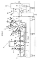
- the packaging machine comprises an endless conveyor 1 and a mandrel wheel 4 disposed above the starting end of the path of transport of the conveyor 1 and having a horizontal rotary shaft 2 and eight mandrels 3 extending radially from the shaft 2.
- the conveyor 1 and the mandrel wheel 4 are intermittently driven in synchronism.
- the conveyor 1 comprises a pair of chains 5 movable in circulation in a horizontal plane, a multiplicity of holders 6 attached to the chains 5 at a predetermined spacing and a rail 7 for supporting the bottoms of bottomed tubular blanks C.
- the blanks C are transported by the conveyor 1 from the rear forward as indicated by an arrow A.
- the mandrel wheel 4 is driven counterclockwise in Fig.
- the conveyor 1 and the mandrel wheel 4 are entirely enclosed in a closed main chamber 8.
- the main chamber 8 is filled with clean air which has been sterilized.
- a series of devices 9 are arranged on the top wall of the main chamber 8 from the rear forward in succession. These devices include primary and secondary bottom heaters 10, 11 for heating the end of the tubular blank C to be made into the bottom of a container, a bottom breaker 12 for folding the end to a flat form, a bottom sealer 13 for pressing the flatly folded end, a primary top breaker 14 for forming folds in the other end of the tubular blank C so as to render the end easily foldable into a roof form to provide the top of the container, a filling device 15 for filling a predetermined amount of contents into the bottomed tubular blank C, a secondary top breaker 16 for eventually folding the end in the form of a roof along the folds formed by the primary top breaker 14, a top heater 17 for heating the end thus folded and a top sealer 18 for pressing the end.
- the primary and secondary bottom heaters 10, 11, the bottom breaker 12 and the bottom sealer 13 are arranged at the positions where the mandrels stop.
- the portions of the group of devices 9 which operate on the blank C extend into the main chamber 8.
- the wall portions of the main chamber 8 through which these operating portions of the devices extend into the main chamber are completely prevented from passing air therethrough with use of bellows for the operating portion which performs a reciprocating rectilinear motion or with use of an oil seal or mechanical seal for the operating portion which performs a rotary motion.
- the series of devices 9 are all those already known.
- the main chamber 8 is internally provided with a cleaning-sterilizing system 19 and a clean air supply system 20.
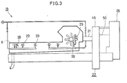
- a closed subchamber 22 is disposed to the rear of the main chamber 8 and made to communicate therewith by a booth 21.
- a blank sterilizer 23 and a blank transfer assembly 24 are arranged within the subchamber 22.
- a blank shaping-feeding unit 25 is provided outside the subchamber 22.
- the blank shaping-feeding unit 25 is enclosed in its entirety in a rear chamber 26 which, however, is not of closed construction unlike the chambers 8 and 22.
- the unit 25, which is of the known type, is adapted to shape folded flat blanks C into a tubular form.
- the unit 25 includes a magazine 27 having stacked therein a multiplicity of folded flat blanks C although now shown.
- the blank transfer assembly 24 is adapted to transfer blanks C shaped to a tubular form from the blank shaping-feeding unit 25 to the blank sterilizer 23 and to transfer sterilized tubular blanks C from the sterilizer 23 to the mandrel wheel 4.
- the cleaning-sterilizing system 19 comprises spray nozzles 28, spray balls 29 and sterilizing solution spray nozzles 30 which are arranged within the main chamber 8 as required.
- the conveyor 1 is operated with a cleaning solution forced out from the spray nozzles 28 and balls 29, whereby the conveyor 1 and the interior of the main chamber 8 can be cleaned automatically.
- a sterilizing solution when applied by the spray nozzles 30, sterilizes the conveyor 1 and the interior of the main chamber 8.
- An aqueous solution of hydrogen peroxide with a concentration of 35% is used as the sterilizing solution.
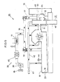
- Fig. 5 shows the clean air supplying system 20.
- the main chamber 8 has a completed container discharge opening 31 at the front end thereof.
- the subchamber 22 has a blank supply opening 32 at a rear portion thereof. These openings 31 and 32 are provided with openable closures 33 and 34 respectively.
- Branched air supply ducts 36 extending from an air supply unit 35 are connected to. the main chamber 8 and the sub- chamber 22 and are each provided with a check valve 37.
- the air supply unit 35 comprises an air intake filter 38, an electric blower 39, a sterilizing filter 40 and a heater 41.
- An air discharge duct 42 is connected to suitable portions of the main chamber 8 and the subchamber 22 and is open to the atmosphere through a shutoff valve 43.
- the system 20 is further provided with a pressure sensor 44 for detecting the internal pressure of the main chamber 8, such that when the pressure detected drops below a set level, the air supply unit 35 operates in response to an output signal from the sensor 44.
- the air supply duct 36 is also connected to the blank sterilizer 23 (see Figs. 6 to 8).
- the supply ducts 36 are shut off from the chambers 8, 22 by the check valves 37 and separated from the atmosphere by the sterilizing filter 40, so that the ducts 36 are made free from contaminants. This eliminates the need for routine sterilization of the supply ducts 36. If the internal pressure of the chambers 8, 22 decreases for one cause or another, the sensor 44 detects the pressure drop to operate the electric blower 39 and to thereby maintain the interior of the chambers 8, 22 at the specified positive pressure level at all times.
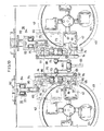
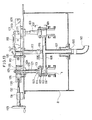
- Figs. 6 to 8 show the subchamber 22 and the blank sterilizer 23 in detail.
- the subchamber 22 comprises a drying compartment 46 having at its front portion a blank outlet 45 communicating with the main chamber 8, a sterilizing compartment 49 communicating at its front portion with the drying compartment 46 through an opening 47 and having a blank inlet 48 at its rear portion, and a pressurized compartment 50 enclosing an opening, including the blank inlet 48, of the sterilizing compartment 49.
- the drying compartment 46 is in the form of a flat case having a thickness in the front-to-rear direction and is formed with the blank outlet 45 in its front wall.
- the air supply duct 36 and the air discharge duct 42 are connected to the top wall of the drying compartment 46.
- the sterilizing compartment 49 is in the form of a bottomed horizontal hollow cylinder having an open front end which is attached to the rear wall of the drying compartment and thereby closed.
- the blank inlet 48 is positioned to the rear of the communication opening 47 in alignment therewith.
- the pressurized compartment 50 is in the form of a case open at its front end and having such a size as to cover the sterilizing compartment 49 with a required space formed therein around the compartment 49.
- the open end of the pressurized compartment 50 is intimately attached to and closed by the rear wall of the drying compartment 46.
- the aforementioned blank supply opening 32 is formed in the rear wall of the compartment 50.
- the air supply duct 36 is also connected to the top wall of the pressurized compartment 50.
- the blank sterilizer 23 comprises a drying conveyor 51 disposed within the drying compartment 46, a sterilizing conveyor 52 disposed within the sterilizing compartment 49, hot air blowing nozzles 53 arranged along the path of transport of the drying conveyor 51, and a blank sterilizing spray nozzle 54 directed toward the path of transport of the sterilizing conveyor 52.
- the drying conveyor 51 comprises drive and driven sprockets 55, 56 having axes of rotation spaced apart by a predetermined distance one above the other and extending in the front-to-rear direction, endless chains 57 reeved around the spockets 55 r 56 and a multiplicity of drying blank holders 58 attached to the endless chains 57 at a predetermined spacing.
- the drying conveyor 51 is so disposed within the drying compartment 46 that each of the holders 58 travels passing positions opposed to the blank outlet 45 and the communication opening 47.
- the sterilizing conveyor 52 comprises a horizontal rotary shaft 59 extending in the front-to-rear direction and four sterilizing blank holders 60 attached to the rotary shaft 59 and arranged around the rotary shaft at a predetermined spacing.
- the sterilizing conveyor 52 is so disposed within the sterilizing compartment 49 that each of the holders 60 travels passing a position opposed to the communication opening 47 and the blank inlet 48.
- Both the drying and sterilizing blank holders 58 and 60 are of the same shape and comprise a plurality of horizontal pieces to be positioned around the tubular blank C to retain the blank C in a horizontal position, restraining the blank from upward or downward movement but allowing the blank to move forward or rearward.
- the hot air blowing nozzles 53 are attached to a hot air supply duct 61 extending vertically within the drying compartment 46 and are arranged at the same spacing as the drying blank holders 58.
- the orifices of the nozzles 53 are directed in the axial direction of the holders 58.
- the upper end of the duct 61 extends through the top wall of the drying chamber 46 upward, with a heat insulating tube 62 provided around the duct 61.
- the top end of the duct 61 has the air supply duct 36 connected thereto and a burner 63 attached thereto.
- the nozzle 54 for spraying a solution for sterilizing the blank is mounted on the bottom of a bottomed tube 64.
- the tube 64 extends in the front-to-rear direction across the drying compartment 46 so as to be positioned in front of and in alignment with each of the sterilizing blank holders 60 when the holder 60 depends from the rotary shaft 59.
- the tube 64 is provided in the drying compartment 46 with its open end communicating with the sterilizing compartment 49.
- the orifice of the spray nozzle 54 is oriented in the axial direction of the blank holder 60.
- the drive sprockets 55 of the drying conveyor 51 are fixed to a rotary shaft 65 extending from the rear wall of the drying compartment 46 forward through the front wall thereof.
- a pulley 66 is fixedly mounted on the end of the shaft 65 projecting outward from the compartment 46.
- a belt 67 is reeved around the pulley 66 and another pulley fixed to the output shaft of an unillustrated prime mover.
- the drying conveyor 51 is intermittently driven by the belt 67 so that the holders 58 thereon can be stopped at the positions opposed to the blank outlet 45 and the communication opening 47.
- the horizontal rotary shaft 59 of the sterilizing conveyor 52 is supported by a tube 68 attached to the rear end of the drying compartment 46.
- the front end of the rotary shaft 59 extends into the drying compartment 46, and drive sprockets 69 are fixed to the front end.
- the sprockets 69 are in mesh with the endless chains 57 so that the holders 60 of the sterilizing conveyor 52 can be stopped at the position opposed to the communication opening 47 and the blank outlet 48.
- the sterilizing conveyor 52 is intermittently driven in synchronism with the drying conveyor 51.
- the drive interval is 90 degrees in terms of the revolution of the holders 60, i.e. one pitch of the holders 60.
- a blank guide 70 provided within the booth 21 in front of the drying compartment 46 is opposed to the blank outlet 45 of the compartment 46, while a blank guide 71 is provided within the pressurized compartment 50 and positioned in the rear of and opposed to the blank inlet 48 of the sterilizing chamber 49.
- the blank guides 70, 71 are generally identical with the blank holders 58, 60 in shape.
- the air discharge duct 42 extending through the drying compartment 46 and the pressurized compartment 50 is connected to a lower portion of the sterilizing compartment 49.
- the interior of the pressurized compartment 50 is maintained at a higher pressure than the interior of the sterilizing compartment 49 because clean air is rapidly fed to the pressurized compartment 50 through the air supply duct 36 and further because air is rapidly discharged from the sterilizing compartment 49 via the air discharge duct 42. Accordingly the air within the sterilizing compartment 49 will not flow out into the pressurized compartment 50, and the sterilizing solution sprayed into the compartment 49 is discharged with the air discharged via the duct 46. This prevents air pollution with the sterilizing solution.
- Figs. 6, 9 and 10 show the blank transfer assembly 24 in detail.
- the blank transfer assembly 24 comprises a pair of upper and lower horizontal guide rods 72 extending in the front-to-rear direction at one side of the sterilizing compartment 49 within the pressurized compartment 50, a carriage 74 movably supported by rollers 73 on the guide rods 72, a pair of upper and lower pawl rods 77, 78 extending in the front-to-rear direction, rotatably supported by brackets 75, 76 on the carriage 74 and spaced apart by a predetermined distance from each other in parallel, an upper pawl 79 fixed to the upper pawl rod 77, and first and second lower pawls 80, 81 fixed to the lower pawl rod 78 and spaced apart from each other by a predetermined distance in the front-to-rear direction.
- the horizontal guide rods 72 are supported, in the vicinity of their front ends, by the rear wall of the drying compartment 46 in a cantilever fashion.
- the forward end of a drive arm 83 is connected to the carriage 74 by a link 82.
- the drive arm 83 is supported by a transverse horizontal shaft 84.
- the drive arm 83 when pivotally moved by unillustrated means, moves the carriage 74 forward and rearward in reciprocation along the guide rods 72.
- a major portion of the upper pawl rod 77 extends into the drying compartment 46 through a hole 85 formed in the rear wall of the compartment 46.
- the upper and lower pawl rods 77, 78 are interconnected by a pair of arms 86, 87 and a link 88 so as to transmit rotation to each other.
- Lift means 91 is connected to the arm 89 by a connecting member 90.
- the lift means 91 comprises a lift rod 92, a pair of opposed horizontal guide rails 93 fixed to the lower end of the lift rod 92 and extending in the front-to-rear direction, and a trolley 94 supported by the rails 93.
- the lift rod 92 is movable upward and downward by an unillustrated cyli-nder.
- the peripheral wall of the sterilizing compartment 49 is formed with an aperture 95, through which the first and second lower pawls 80 and 81 are movable into the sterilizing compartment 49.
- these pawls are engageable with blanks C.
- the upper pawl 79 is engageable with or disengageable from the blank C held by the drying blank holder 58 which is at rest in the position opposed to the blank outlet 45 of the drying compartment 46.
- the first lower pawl 80 is engageable with or disengageable from the blank C held by the sterilizing blank holder 60 which is at rest as opposed to the communication opening 47 and to the blank inlet 48.
- the second lower pawl 81 is engageable with or disengageable from the blank C which is to be held by the sterilizing blank holder 60.
- the last-mentioned blank C is retained by the blank guide 71 within the pressurized compartment 50.
- another pawl is secured to the upper pawl rod 77 to the front of the upper pawl 79.
- This pawl serves to forward the blank C which has been removed from the drying blank holder 58 by the upper pawl 79.
- This blank C is sent forward by being guided by the blank holder 70 within the booth 21.
- the carriage 74 further has a horizontal rod 96 extending rearward therefrom under the lower pawl rod 78 and fixedly provided with an engaging piece 97 at its rear end.
- the blank C which had been forwarded from the blank shaping-feeding unit 25 is brought by the engaging piece 97 into the range of stroke of the second lower pawl 81, i.e. to the position where it is to be held by the blank guide 71.
- the blank C shaped into a tubular form by the unit 25 is sent forward by the engaging piece 97 and the second lower pawl 81 and held by one of the sterilizing blank holders 60.
- the holder 60 is at rest on a horizontal line through the horizontal rotary shaft 59.
- the sterilizing conveyor 52 When the sterilizing conveyor 52 is driven by one pitch, the same blank C is brought to a position opposed to the spray nozzle 54 in alignment therewith and is exposed to a spray of sterilizing agent from the nozzle 54, whereby the blank is uniformly sterilized over the inner and outer surfaces thereof. Subsequently the conveyor 52 is driven by three pitches, whereby the sterilized blank C is moved round the shaft 59 and returned to the original position within the compartment 49. When at rest in this position, the blank is forwarded by the first lower pawl 80 and is thereby removed from the holder 60 and held by one of the drying blank holders 58. Another blank C is placed by the second lower pawl 81 onto the sterilizing blank holder 60 from which the above blank C has been withdrawn.
- the blank C held by the drying blank holder 58 is sterilized and dried by the hot air blowing nozzles 53 during travel through the drying compartment 46.
- the same blank C is brought to a halt at a position two pitches preceding the initial position after travelling through the drying compartment 46 the blank is removed from the sterilizing blank holder 58 and sent forward by the upper pawl 79.
- the blank C thus withdrawn from the holder 58 is further forwarded as retained on the blank guide 70 and fed to the main chamber 8.
- Figs. 11 to 14 show the filling device 15.
- the filling device 15 comprises a filling liquid tank 98, a filling cylinder 100 connected at its upper end to the bottom of the liquid tank 98 by a branch pipe 99 so as to communicate with the tank 98, a metering cylinder 102 connected to an intermediate portion of the filling cylinder 100 between its upper and lower ends by a connecting pipe 101, and a filling nozzle 103 connected to the lower end of the filling cylinder 100.
- a liquid supply pipe 104 is connected to the liquid tank 98.
- a cleaning solution supply pipe 105 extending from the cleaning-sterilizing system 19 is connected to the liquid tank 98 and to the metering cylinder 102.
- the filling nozzle 103 extends into the main chamber 8 through the top wall thereof and has an open lower end which is positioned immediately above the path _of transport of blanks. Filling operation is conducted twice for each bottomed tubular blank C, so that two adjacent, front and rear filling nozzles 103 are arranged along the transport path.
- a liquid conduit 106 is disposed under the filling nozzles 103 within the main chamber 8.
- the liquid conduit 106 comprises a vertical portion 107 rotatably and vertically movably supported by the main chamber 8 at a location a predetermined distance sidewise away from immediately below the filling nozzles 103, and a horizontal portion 108 integral with the vertical portion 107 and having a length corresponding to the above- mentioned distance.
- the lower end of the vertical portion 107 extends outward from the main chamber 8 through its bottom wall, with a tubular seal member 109 fitted in the wall around the lower end.
- a liquid discharge pipe 110 is connected to the seal member 109.
- a liquid receptacle 111 is attached to the forward end of the horizontal portion 108.
- the liquid receptacle 111 is formed with two upwardly open nozzle sockets 112 corresponding to the two adjacent filling nozzles 103 and communicating with the liquid conduit 106.
- An annular seal member 113 of elastic material is attached to the inner periphery of each socket 112.
- a pair of opposed engaging pieces 114 projecting upward are attached to opposite sides of the liquid receptacle 111.
- a laterally U-shaped cutout 115 is formed in each engaging piece 114 as seen in Fig. 14.
- a rotating rod 116 is connected to the upper end of the vertical portion 107 of the conduit 106 in alignment with the portion 107.
- the rotating rod 116 slidably extends through and projects upward from a guide tube 117 attached to the top wall of the main chamber 8.
- a handle 118 is attached to the projecting end of the rod 116.
- the handle 118 is supported by the top wall of the main chamber 118 by means of a vertical solid cylindrical spacer 119 upstanding from the chamber 8 and a horizontal contact disk 120 fixed to the upper end of the spacer.
- the handle 118 when rotated, causes the rotating rod 116 and the liquid conduit 106 to revolve the liquid receptacle 111 in a horizontal plane.
- the filling nozzles 103 are provided with a vertically movable rod 121 extending upward from their lower ends.
- the lower end of the rod 121 is integral with an engaging member 122 extending horizontally laterally.
- the vertically movable rod 121 is slidably inserted through a guide tube 123 attached to the top wall of the main chamber 8, further slidably extends through a slide guide plate 124 mounted on the upper side of the top wall of the main chamber 8 immediately above the tube 123 and has its upper end projected upward beyond the plate 124.
- a rectangular tube 125 is held to the projecting end.
- the lateral opposite sides of the rectangular tube 125 are in bearing contact with a pair of blocks 126 having the same front-to-rear thickness as the tube 125 and adapted for guiding vertical movement.
- a projection 127 is integral with each of the front and rear sides of the rectangular tube 125.
- the tube 125 and the guide blocks 126 on opposite sides thereof are held between a pair of front and rear movable plates 128 which are rectangular and laterally elongated and which are laterally movably placed on the slide guide plate 124, the movable plates 128 being slidable on the front and rear surfaces of the tube 125 and the blocks 126.
- Each movable plate 128 is formed with a slot 129 having the projection 127 fitted therein.
- the slot 129 is slanted upwardly rightward as seen in Fig. 13.
- a threaded member 130 is held between the two movable plates 128 at one side of the chamber 8.
- a screw rod 132 supported by a bearing 131 on the top wall of the main chamber 8 has its one end screwed in the threaded member 130.
- a rotary handle 133 is attached to the other end of the screw rod 132.
- the horizontal portion 108 of the liquid conduit 106 is oriented in the front-to-rear direction so as not to interfere with the blanks C transported on the endless conveyor 1.
- the liquid receptacle 111 is revolved in the manner already described and positioned immediately below the open lower ends of the filling nozzles 103, whereby the engaging pieces 114 are fitted at the cutouts 115 to the engaging member 112 of the vertically movable rod 121.
- the liquid receptacle 111 is positioned in place immediately below the filling nozzles 103 and engaged with the vertically movable rod 121.
- the screw rod 132 rotates, moving the movable plates 128 leftward in Fig. 13 along with the threaded member 130 which is screwed on the rod 132.
Landscapes
- Engineering & Computer Science (AREA)
- Mechanical Engineering (AREA)
- Chemical & Material Sciences (AREA)
- Dispersion Chemistry (AREA)
- Apparatus For Disinfection Or Sterilisation (AREA)
Claims (10)
Priority Applications (2)
| Application Number | Priority Date | Filing Date | Title |
|---|---|---|---|
| DE8484200766T DE3467880D1 (en) | 1984-05-26 | 1984-05-26 | Packaging machine |
| EP19840200766 EP0162968B1 (fr) | 1984-05-26 | 1984-05-26 | Machine d'emballage |
Applications Claiming Priority (1)
| Application Number | Priority Date | Filing Date | Title |
|---|---|---|---|
| EP19840200766 EP0162968B1 (fr) | 1984-05-26 | 1984-05-26 | Machine d'emballage |
Publications (2)
| Publication Number | Publication Date |
|---|---|
| EP0162968A1 EP0162968A1 (fr) | 1985-12-04 |
| EP0162968B1 true EP0162968B1 (fr) | 1987-12-02 |
Family
ID=8192444
Family Applications (1)
| Application Number | Title | Priority Date | Filing Date |
|---|---|---|---|
| EP19840200766 Expired EP0162968B1 (fr) | 1984-05-26 | 1984-05-26 | Machine d'emballage |
Country Status (2)
| Country | Link |
|---|---|
| EP (1) | EP0162968B1 (fr) |
| DE (1) | DE3467880D1 (fr) |
Families Citing this family (15)
| Publication number | Priority date | Publication date | Assignee | Title |
|---|---|---|---|---|
| US4734268A (en) * | 1986-04-14 | 1988-03-29 | Elotrade Ag | Clean air system |
| FR2622406B1 (fr) * | 1987-10-30 | 1990-01-26 | Desjonqueres Olivier | Dispositif de traitement de produits sous atmosphere et temperature controlees, notamment d'emulsions alimentaires |
| FR2624475B1 (fr) * | 1987-12-09 | 1990-04-06 | Olivier Desjonqueres | Dispositif de traitement, en cycle ininterrompu, de produits sous atmosphere et temperature controlees, notamment d'emulsions alimentaires |
| CA1319807C (fr) * | 1988-05-06 | 1993-07-06 | Takuya Adachi | Appareil a steriliser |
| US5262126A (en) * | 1988-05-10 | 1993-11-16 | Toppan Printing Co., Ltd. | Method of sterilizing laminated packaging material |
| EP0342485B1 (fr) * | 1988-05-10 | 1993-01-07 | Toppan Printing Co., Ltd. | Procédé de stérilisation de matériel d'emballage stratifié |
| JP2525526Y2 (ja) * | 1989-02-17 | 1997-02-12 | 四国化工機 株式会社 | 包装機械 |
| EP0405402A3 (en) * | 1989-06-26 | 1991-03-20 | Toyo Seikan Kaisha Limited | Aseptic filling machine |
| JP2582559Y2 (ja) * | 1992-02-03 | 1998-10-08 | 四国化工機株式会社 | 充填機の洗浄装置 |
| DE19741242C1 (de) * | 1997-09-18 | 1999-07-08 | Diversey Lever Gmbh | Anlage zum Reinigen einer Abfüllanlage |
| DE102009029706A1 (de) * | 2009-06-08 | 2010-12-09 | Sig Technology Ag | Verfahren und Vorrichtung zum Entkeimen von Verpackungen |
| DE102011111523B8 (de) * | 2011-08-31 | 2013-03-28 | Sig Technology Ag | Verfahren und Vorrichtung zur Kantenentkeimung von Verpackungsmaterial |
| US9751027B2 (en) | 2011-09-29 | 2017-09-05 | Cameron International Corporation | Interface and mud control system and method for refinery desalters |
| WO2017142779A1 (fr) * | 2016-02-18 | 2017-08-24 | Cameron International Corporation | Interface et système de régulation de boues et procédé pour dessaleurs de raffinerie |
| IT201600082954A1 (it) * | 2016-08-05 | 2018-02-05 | Fater Spa | Impianto per la produzione di prodotti cosmetici, in particolare per la produzione di salviette umidificate |
Family Cites Families (6)
| Publication number | Priority date | Publication date | Assignee | Title |
|---|---|---|---|---|
| US3723060A (en) * | 1968-02-26 | 1973-03-27 | Ex Cell O Corp | Aseptic packaging machine |
| SE335090B (fr) * | 1968-10-30 | 1971-05-10 | Tetra Pak Int | |
| FR2120765A5 (en) * | 1970-12-28 | 1972-08-18 | Hamba Maschinen H Muller | Packaging liquid foods - automatically and sterilising containers |
| FR2292661A1 (fr) * | 1974-11-30 | 1976-06-25 | Shibuya Kogyo Co Ltd | Dispositif de lavage pour machine de remplissage rotative |
| EP0013132B1 (fr) * | 1978-12-19 | 1984-03-28 | Liquipak International B.V. | Appareil comprenant un dispositif de dosage pour produit liquide et methode correspondante |
| JPS5917413A (ja) * | 1982-07-15 | 1984-01-28 | Shikoku Kakoki Co Ltd | 包装機械 |
-
1984
- 1984-05-26 DE DE8484200766T patent/DE3467880D1/de not_active Expired
- 1984-05-26 EP EP19840200766 patent/EP0162968B1/fr not_active Expired
Also Published As
| Publication number | Publication date |
|---|---|
| EP0162968A1 (fr) | 1985-12-04 |
| DE3467880D1 (en) | 1988-01-14 |
Similar Documents
| Publication | Publication Date | Title |
|---|---|---|
| US4590734A (en) | Packaging machine | |
| EP0162968A1 (fr) | Machine d'emballage | |
| FI94331B (fi) | Menetelmä ja laite täyttöaukolla varustettujen säiliöiden steriloimiseksi | |
| US12594586B2 (en) | Cleaning method for cleaning a filling machine and filling machine for carrying out the cleaning method | |
| US20220340320A1 (en) | Bag processing machine | |
| EP0903297B1 (fr) | Hotte à air pur pour machine d'emballage | |
| EP0340790B1 (fr) | Dispositif de stérilisation | |
| JPH0629080B2 (ja) | 無菌充てん装置 | |
| US5072747A (en) | Apparatus and method for cleaning tubular articles | |
| JPS627047B2 (fr) | ||
| JPS6241932B2 (fr) | ||
| JPS627048B2 (fr) | ||
| JPS627049B2 (fr) | ||
| JP2025527332A (ja) | コンテナの除染のための供給ステーション | |
| JPS6215430B2 (fr) | ||
| JPH0114097B2 (fr) | ||
| JP3239386B2 (ja) | 殺菌装置 | |
| JPH0114094B2 (fr) | ||
| JPS61244726A (ja) | 包装機械 | |
| EP0383408B1 (fr) | Machine d'emballage | |
| JPS6215408B2 (fr) | ||
| JPH063778Y2 (ja) | 無菌包装装置 | |
| JP3239397B2 (ja) | 殺菌装置 | |
| JPS61273307A (ja) | 包装機械 | |
| JPH07187150A (ja) | 包装機械 |
Legal Events
| Date | Code | Title | Description |
|---|---|---|---|
| PUAI | Public reference made under article 153(3) epc to a published international application that has entered the european phase |
Free format text: ORIGINAL CODE: 0009012 |
|
| AK | Designated contracting states |
Designated state(s): DE FR GB NL SE |
|
| 17P | Request for examination filed |
Effective date: 19860201 |
|
| 17Q | First examination report despatched |
Effective date: 19860825 |
|
| GRAA | (expected) grant |
Free format text: ORIGINAL CODE: 0009210 |
|
| AK | Designated contracting states |
Kind code of ref document: B1 Designated state(s): DE FR GB NL SE |
|
| REF | Corresponds to: |
Ref document number: 3467880 Country of ref document: DE Date of ref document: 19880114 |
|
| ET | Fr: translation filed | ||
| PLBE | No opposition filed within time limit |
Free format text: ORIGINAL CODE: 0009261 |
|
| STAA | Information on the status of an ep patent application or granted ep patent |
Free format text: STATUS: NO OPPOSITION FILED WITHIN TIME LIMIT |
|
| 26N | No opposition filed | ||
| EAL | Se: european patent in force in sweden |
Ref document number: 84200766.8 |
|
| REG | Reference to a national code |
Ref country code: GB Ref legal event code: IF02 |
|
| PGFP | Annual fee paid to national office [announced via postgrant information from national office to epo] |
Ref country code: FR Payment date: 20020329 Year of fee payment: 19 |
|
| PGFP | Annual fee paid to national office [announced via postgrant information from national office to epo] |
Ref country code: SE Payment date: 20020514 Year of fee payment: 19 |
|
| PGFP | Annual fee paid to national office [announced via postgrant information from national office to epo] |
Ref country code: GB Payment date: 20020522 Year of fee payment: 19 |
|
| PGFP | Annual fee paid to national office [announced via postgrant information from national office to epo] |
Ref country code: NL Payment date: 20020528 Year of fee payment: 19 |
|
| PG25 | Lapsed in a contracting state [announced via postgrant information from national office to epo] |
Ref country code: GB Free format text: LAPSE BECAUSE OF NON-PAYMENT OF DUE FEES Effective date: 20030526 |
|
| PG25 | Lapsed in a contracting state [announced via postgrant information from national office to epo] |
Ref country code: SE Free format text: LAPSE BECAUSE OF NON-PAYMENT OF DUE FEES Effective date: 20030527 |
|
| PGFP | Annual fee paid to national office [announced via postgrant information from national office to epo] |
Ref country code: DE Payment date: 20030528 Year of fee payment: 20 |
|
| PG25 | Lapsed in a contracting state [announced via postgrant information from national office to epo] |
Ref country code: NL Free format text: LAPSE BECAUSE OF NON-PAYMENT OF DUE FEES Effective date: 20031201 |
|
| EUG | Se: european patent has lapsed | ||
| GBPC | Gb: european patent ceased through non-payment of renewal fee |
Effective date: 20030526 |
|
| PG25 | Lapsed in a contracting state [announced via postgrant information from national office to epo] |
Ref country code: FR Free format text: LAPSE BECAUSE OF NON-PAYMENT OF DUE FEES Effective date: 20040130 |
|
| NLV4 | Nl: lapsed or anulled due to non-payment of the annual fee |
Effective date: 20031201 |
|
| REG | Reference to a national code |
Ref country code: FR Ref legal event code: ST |