EP0162984B1 - Befestigungseinrichtung - Google Patents
Befestigungseinrichtung Download PDFInfo
- Publication number
- EP0162984B1 EP0162984B1 EP84308623A EP84308623A EP0162984B1 EP 0162984 B1 EP0162984 B1 EP 0162984B1 EP 84308623 A EP84308623 A EP 84308623A EP 84308623 A EP84308623 A EP 84308623A EP 0162984 B1 EP0162984 B1 EP 0162984B1
- Authority
- EP
- European Patent Office
- Prior art keywords
- load
- screw
- thread
- fastening assembly
- fastener
- Prior art date
- Legal status (The legal status is an assumption and is not a legal conclusion. Google has not performed a legal analysis and makes no representation as to the accuracy of the status listed.)
- Expired
Links
- 239000012774 insulation material Substances 0.000 claims description 32
- 238000005553 drilling Methods 0.000 claims description 7
- 230000008878 coupling Effects 0.000 claims description 6
- 238000010168 coupling process Methods 0.000 claims description 6
- 238000005859 coupling reaction Methods 0.000 claims description 6
- 239000000463 material Substances 0.000 claims description 6
- 238000010079 rubber tapping Methods 0.000 claims description 4
- 239000004743 Polypropylene Substances 0.000 claims description 3
- -1 polypropylene Polymers 0.000 claims description 3
- 229920001155 polypropylene Polymers 0.000 claims description 3
- 238000001746 injection moulding Methods 0.000 claims description 2
- 229920001169 thermoplastic Polymers 0.000 claims description 2
- 239000004416 thermosoftening plastic Substances 0.000 claims description 2
- 239000012528 membrane Substances 0.000 description 8
- 230000000712 assembly Effects 0.000 description 6
- 238000000429 assembly Methods 0.000 description 6
- 229920001971 elastomer Polymers 0.000 description 6
- 238000011068 loading method Methods 0.000 description 5
- 230000004888 barrier function Effects 0.000 description 4
- XLYOFNOQVPJJNP-UHFFFAOYSA-N water Substances O XLYOFNOQVPJJNP-UHFFFAOYSA-N 0.000 description 4
- 150000001875 compounds Chemical class 0.000 description 3
- 239000002184 metal Substances 0.000 description 3
- 238000007789 sealing Methods 0.000 description 3
- 229910000746 Structural steel Inorganic materials 0.000 description 1
- 230000032683 aging Effects 0.000 description 1
- 229920005549 butyl rubber Polymers 0.000 description 1
- 239000011248 coating agent Substances 0.000 description 1
- 238000000576 coating method Methods 0.000 description 1
- 239000003086 colorant Substances 0.000 description 1
- 230000000295 complement effect Effects 0.000 description 1
- 238000010276 construction Methods 0.000 description 1
- 230000008602 contraction Effects 0.000 description 1
- 239000007799 cork Substances 0.000 description 1
- 239000013536 elastomeric material Substances 0.000 description 1
- 230000005484 gravity Effects 0.000 description 1
- 238000002347 injection Methods 0.000 description 1
- 239000007924 injection Substances 0.000 description 1
- 238000009413 insulation Methods 0.000 description 1
- 238000004519 manufacturing process Methods 0.000 description 1
- 239000011490 mineral wool Substances 0.000 description 1
- 239000004033 plastic Substances 0.000 description 1
- 229920003023 plastic Polymers 0.000 description 1
- 229920000642 polymer Polymers 0.000 description 1
- 238000004804 winding Methods 0.000 description 1
Images

Classifications
-
- E—FIXED CONSTRUCTIONS
- E04—BUILDING
- E04D—ROOF COVERINGS; SKY-LIGHTS; GUTTERS; ROOF-WORKING TOOLS
- E04D3/00—Roof covering by making use of flat or curved slabs or stiff sheets
- E04D3/36—Connecting; Fastening
- E04D3/3601—Connecting; Fastening of roof covering supported by the roof structure with interposition of a insulating layer
- E04D3/3603—Connecting; Fastening of roof covering supported by the roof structure with interposition of a insulating layer the fastening means being screws or nails
Definitions
- This invention relates to fastening assemblies for fastening compressible insulation material onto a roof decking.
- a built up roof is made by providing a relatively thin sheet metal roof decking covering a framework of structural steel members. Insulation material such as mineral wool mat is then laid over the decking and secured in place by fastener assemblies. The insulation material and fastener assemblies are then covered by a waterproof membrane, for example a butyl rubber sheet or by a combination of roofing felt and a bitumastic sealing compound.
- the thickness of the insulation be increased to a thickness within a range from 130 to 300 mm.
- One particular application of this is to provide a gravity fall on a flat roof deck by providing a graduated thickness of insulation material over the roof decking to convert a flat roof into one having a shallow pitch.
- a fastening assembly for use in fastening a thick insulating layer onto a roof decking comprising a self drilling and self tapping screw-threaded fastener having a driving head; and a load distributing plate for engaging the upper surface of the insulation material to hold the insulation material and distribute the fastening load so that the fastening assembly does not pull through the insulation material is known for example from FR-A-2 344 735.
- an extensible resilient member having one end coupled to the head of the screw-threaded fastener and the other end coupled to the load distributing plate, at least one of said couplings permitting the screw-threaded fastener to rotate with respect to the load distributing plate to allow the fastener to be driven through and screwed into the roof decking to fasten the insulation material.
- a resilient element between the load-distributing plate and the screw-threaded fastener firstly enables the insulation material to be held under a substantially constant tensile load irrespective of minor variations in the manufacture of the insulation material, and distortions and deformations of it that occur in use. Such deformations can occur by the ageing of the material or during the application of an external load to the roof, for example a snow loading or a wind loading, or as a result of roof traffic. Another cause of deformation in the insulation material is the way it settles at the corrugations of the roof decking due to roof load.
- the resilient element also accommodates any lateral movement of the load-distributing plate and the screw-threaded fastener caused by, for example, thermal expansion and contraction or settlement of the building.
- the resilient element may be formed by a polymer spring or an extensible element of rubber or rubber-like elastomeric material.
- the resilient element may be moulded integrally with the load-distributing plate at one end and its other end preferably includes a fixing including a circular apertures to enable the screw-threaded fastener to be coupled to it and to enable the screw-threaded fastener to rotate with respect to the element.
- the resilient element is formed by a helically wound wire tension spring having at one end a turn of smaller diameter than the remainder through which the screw-threaded fastener passes and against which the head of the screw-threaded fastener engages to form the coupling between the fastener and the spring.
- the turn of smaller diameter may be spaced from the remainder of the spring by a straight and generally axially extending arm portion.
- a range of fastening assemblies may be provided and these may have different lengths of axially extending arm portions to enable the fastening assemblies to suit a variety of different thicknesses of insulation material.
- the load-distributing plate includes a depending projection carrying an external helical track and the other end of the helically wound wire tension spring is coupled to the load-distributing plate by being wound onto this projection with the turns of the spring being received in the track.
- the helix angle of the track on the projection preferably corresponds to the helix angle of the spring under its normal load condition. Firstly this ensures that the portion of the projection remaining between adjacent turns of the track have sufficient strength to support the spring and secondly ensures that the spring is subjected to a substantially constant loading throughout its connection with the load-distributing plate and this avoids problems such as fatigue failure caused by any point loading on the spring.
- the one end of the spring which is coupled to the load-distributing plate may be formed with a single turn having a steeper helix angle than the remainder of the spring and then this portion of the spring is coupled with the load-distributing plate by winding this single turn of the spring with the steep helix angle into a correspondingly shaped portion of the load-distributing plate in an analogous fashion to the connection between a corkscrew and a cork.
- the single turn of the large helix angle is preferably concluded with a short end portion of the spring having a zero helix angle.
- the corresponding portion of the load-distributing plate includes a helical surface to support the end of the spring having a zero helix angle and, in this case, the final straight portion of the spring with zero helix angle co-operates with the helical surface on the load-distributing plate to provide a substantially uniform load-distribution around the entire angular extent of the load-distributng plate and again avoids point loadings leading to fatigue failure.
- the fastening assembly preferably includes a rubber or rubber-like elastomeric washer located between the coupling between the head of the screw-threaded fastener and the resilient element, and the impermeable vapour barrier located on top of the roof decking.
- the rubber or rubber-like elastomeric washer forms a vapour-tight seal around the fastener and this ensures the integrity of the impermeable vapour barrier even though the screw-threaded fastners penetrate the impermeable membrane.
- the rubber or rubber-like elastomeric washers also engage the fastener closely and help to maintain the coupling between the fastener and the resilient element.
- the screw-threaded fastener includes a thread-free portion adjacent its head and its screw-thread runs cleanly into this thread-free portion.
- the screw-threaded fastener is coupled to the one end of the resilient element the one end of the resilient element is received in this unthreaded portion so that the fastener is held captive by the resilient element but so that it can rotate with respect to the one end of the resilient element.
- the fastening assembly also includes a rubber or rubber-like elastomeric washer this is also preferably received in this unthreaded portion.
- the unthreaded portion is greater in axial extent than the axial extent of the one end of the resilient element and, where provided, the washer, and preferably it is greater by an amount corresponding to the thickness of the roof decking into which the fastener is to be driven.
- the screw-threaded fasteners are driven until the roof decking runs out into the unthreaded portion. This ensures a constant driving of the fasteners. It is impossible to over-drive the fastener and there is no need for complex torque measuring or resilient element extension measuring systems.
- the length of the screw-threaded fastener which extends through the roof decking is also constant.
- the screw thread on the fastner is preferably generally tapered with the turn of the thread adjacent the groove or unthreaded portion having the maximum diameter.
- the screw-threaded fastener includes a drilling point of TEKS 1 - type (Trade Mark).
- TEKS 1 - type Trade Mark
- the load-distributing plate is preferably formed by injection moulding from a thermoplastics material such as polypropylene.
- the load-distributing plate is domed in its relaxed state so that when it is placed under load it flattens out to exert a substantially constant load over its entire area.
- the plate may be circular, generally square with rounded corners or, to obtain an even greater distribution of the load it may be generally X-shaped with rounded lobes at the ends of the two arms of the X.
- the underside of the load-distributing plate includes a number of ribs extending generally radially outwards to engage the upper surface of the insulation material and help prevent rotation of the plate whilst the fastener is driven into the roof decking.
- the load distributing plates may be made in a range of different colours so that fastening assemblies of a particular overall length have a particular colour of load distributing plate. This enables a fastening assembly of appropriate length for a particular location to be identified readily.
- the load-distributing plate also includes a central aperture through which a driving tool is inserted to engage the driving head of the screw-threaded fastener to rotate it and drive it into the roof decking.
- the upper surface of the load-distributing plate surrounding the aperture includes a lip or a series of resilient fingers extending across the aperture to help prevent bitumastic sealing compound entering the aperture and coating the spring, so adhering adjacent turns together and preventing its free operation.
- the central aperture may be closed by a removable plug.
- the periphery of the plate may also include a lip to co-operate with a driving tool.
- the fastening assembly preferably includes means to prevent the insulation material becoming trapped between adjacent turns of the spring.
- This means may be formed by a sleeve or tube of plastics material surrounding the outside of the turns of the spring.
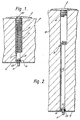
- This example of fastening assembly comprises a self-drilling and self-tapping screw-threaded fastener 1, a load-distributing plate 2 and an extensible resilient member 3.
- the extensible resilient member 3 is formed by a helically wound wire tension spring 4 having at its lowermost end . an axially extending arm portion 5 which terminates in a single turn 6 of small diameter.
- the upper end of the spring 4 is wound onto a projection 7 depending from the load-distributing plate 2 as will be explained in more detail subsequently and the screw-threaded fastener 1 passes through the turn 6 of small diameter.
- this fastening assembly is used to attach a thick layer of insulation material 8 having a thickness typically 130 mm and which may be as great as 300 mm to a metal roof decking 9.
- this metal roof decking 9 is corrugated with trapezoidal corrugations.
- An impermeable membrane may be laid between the insulation material 8 and the roof decking to prevent water vapour permeating through the insulation material 8 and condensing to form water beneath a waterproof membrane laid over the insulation material 8.
- a screw driving tool passes through an aperture 10, shown most clearly in Figures 3 and 4 formed in the load-distributing plate 2 and engages a head 11 of the fastener 1. The fastening assembly is then pushed through the insulation material 8 and then driven by the screw driving tool through the roof decking 9.
- the extensible resilient member 3 is provided with a variety of lengths of axially extending arm portion 5, as shown in Figures 1 and 2.
- the number of coils in the spring 4 also varies with the thickness of the insulation material 8 and the length of the extensible resilient member 3 and there are typically between sixteen and twenty-two working coils.
- the load-distributing plate 2 is injection moulded from polypropylene and includes a circular domed head 12 with four radially extending ribs 13 projecting downwards from its lowermost surface.
- the projection 7 includes a helical track 14 surrounding its projection 7.
- the helical track 14 is arranged to complement the turns 4 of the spring 3 in their loaded state, and the projection 7 is screwed into the upper few turns of the spring 4 to couple the plate 2 onto the spring 4.
- a plug not shown can be inserted into the aperture 10 to prevent bitumastic sealing compound from passing down through the aperture 10.
- a rubber or rubber-like washer 15 is included on the screw beneath the turn of small diameter and this grips the shank of the fastener 1. This washer helps to hold the fastening in its assembled condition but principally it is provided to form a vapour-tight seal beneath the head 11 of the fastener 1. Naturally this is particularly important when the roof includes the impermeable membrane.
- the screw-threaded fastener 1 includes a self-drilling point 16 typically of the TEKS 1 type with a tapering screw thread 17.
- a thread free portion 18 is included in the shank of the fastener 1 between a tapering screw thread 17 and the head 11 and this has sufficient axial extent to accommodate the turn 6 of smaller diameter of the spring 3, the washer 15 when tightly compressed, and the roof decking 9.
- a groove 19 is preferably rolled into the thread-free portion 18.
- the head 11 includes a driving recess such as a number 3-type Philips driving recess.
- the fastening assembly is provided in an assembled condition with the spring 3 screwed onto the projection 7 of the load-distributing plate 2 and with the reduced diameter turn 6 of the spring 3 engaged in the unthreaded portion 18 of the screw-threaded fastener 1.
- the load-distributing plate 2 engages the upper surface of the insulation material 8 and then further downwards movement of the screw driving tool extends the turns 4 of the spring 3 until the drilling point 16 of the fastener is in contact with the roof decking 9.
- Rotation of the fastener 1 causes the drilling point 16 to drill through the roof decking 9 and further rotation causes the self-tapping screw 17 to cut a screw thread in the roof decking 9.
- the turns 4 of the spring 3 are further extended as the fastener 1 is screwed into the decking hence the screw 1 is rotated until the roof decking 9 runs out of the screw thread into the thread-free portion 18.
- the shoulder formed by the run out of the screw thread at the lowermost edge of the thread-free portion 18 resists the tension exerted by the spring 3 to prevent the screw 1 pulling out of the roof decking 9 whilst, ensuring that the screw 1 is always inserted to the correct extent to provide the required tensile load on the load-resisting plate 2 to hold the insulation material 8 onto the decking 9.
- the washer 15 is lightly compressed between the turn 6 of the spring and the decking 9 or impermeable membrane when this is included.
Landscapes
- Engineering & Computer Science (AREA)
- Mechanical Engineering (AREA)
- Architecture (AREA)
- Civil Engineering (AREA)
- Structural Engineering (AREA)
- Roof Covering Using Slabs Or Stiff Sheets (AREA)
- Bolts, Nuts, And Washers (AREA)
- Connection Of Plates (AREA)
- Diaphragms For Electromechanical Transducers (AREA)
Claims (10)
Priority Applications (1)
| Application Number | Priority Date | Filing Date | Title |
|---|---|---|---|
| AT84308623T ATE42366T1 (de) | 1984-01-09 | 1984-12-12 | Befestigungseinrichtung. |
Applications Claiming Priority (4)
| Application Number | Priority Date | Filing Date | Title |
|---|---|---|---|
| GB8400388 | 1984-01-09 | ||
| GB848400388A GB8400388D0 (en) | 1984-01-09 | 1984-01-09 | Fastening assembly |
| GB8413277 | 1984-05-24 | ||
| GB848413277A GB8413277D0 (en) | 1984-05-24 | 1984-05-24 | Fastening assembly |
Publications (3)
| Publication Number | Publication Date |
|---|---|
| EP0162984A2 EP0162984A2 (de) | 1985-12-04 |
| EP0162984A3 EP0162984A3 (en) | 1987-01-28 |
| EP0162984B1 true EP0162984B1 (de) | 1989-04-19 |
Family
ID=26287158
Family Applications (1)
| Application Number | Title | Priority Date | Filing Date |
|---|---|---|---|
| EP84308623A Expired EP0162984B1 (de) | 1984-01-09 | 1984-12-12 | Befestigungseinrichtung |
Country Status (8)
| Country | Link |
|---|---|
| US (1) | US4616455A (de) |
| EP (1) | EP0162984B1 (de) |
| CA (1) | CA1247409A (de) |
| DE (1) | DE3477822D1 (de) |
| DK (1) | DK158365C (de) |
| FI (1) | FI82115C (de) |
| IE (1) | IE56100B1 (de) |
| NO (1) | NO162392B (de) |
Families Citing this family (22)
| Publication number | Priority date | Publication date | Assignee | Title |
|---|---|---|---|---|
| EP0183459A3 (de) * | 1984-11-19 | 1988-05-18 | Ashfield, Jacqueline Margaret | Dach und Methode, ein Gebäude mit einem Dach zu versehen |
| US4762453A (en) * | 1986-01-29 | 1988-08-09 | Textron, Inc. | Helical coil fastener |
| CH676133A5 (de) * | 1986-03-12 | 1990-12-14 | Protan As | |
| US4739599A (en) * | 1987-01-27 | 1988-04-26 | The Dow Chemical Company | Energy dissipation structure for securing lightweight roofing elements |
| US4912895A (en) * | 1987-12-28 | 1990-04-03 | Ford Motor Company | Adjustable spacer |
| US4906154A (en) * | 1988-01-04 | 1990-03-06 | Sheppard William L | Self-adjusting fastener assembly |
| GB2217420A (en) * | 1988-04-09 | 1989-10-25 | Cryotherm Limited | Screws for joining semi-rigid mats |
| US4987714A (en) * | 1988-08-25 | 1991-01-29 | Lemke Stuart H | Method for installing a roof fastener |
| US5255485A (en) * | 1988-08-25 | 1993-10-26 | Stuart H. Lemke | Apparatus and method for installing roofing fasteners |
| FR2707355B1 (fr) * | 1993-07-06 | 1995-08-25 | Lebraut Raymond | Ensemble mécanique anti-vibrations pour le maintien sous tension de divers revêtements, en particulier de revêtements isolants thermiques et sonores. |
| US5426905A (en) * | 1993-09-13 | 1995-06-27 | The United States Of America As Represented By The Secretary Of The Navy | Insulation attachment stud for composite material substrate |
| DE9407231U1 (de) * | 1994-04-30 | 1994-07-14 | Magass, Walter, 69207 Sandhausen | Befestigungselement für Dämm- und Isoliermaterial auf Flachdächern |
| DE19800896C1 (de) * | 1998-01-13 | 2001-04-26 | Deutsch Zentr Luft & Raumfahrt | Einrichtung zum Einleiten einer Kraft in ein Element |
| NO310584B1 (no) * | 1999-10-20 | 2001-07-23 | Laerdal Medical As | Festeanordning for å forbinde to deler med hverandre, samt anvendelse av festeanordningen |
| US6612083B1 (en) | 2001-03-27 | 2003-09-02 | William J. Richards | System of building construction |
| US7144413B2 (en) | 2001-04-20 | 2006-12-05 | Synthes (U.S.A.) | Graft fixation system and method |
| WO2003001074A1 (en) * | 2001-06-21 | 2003-01-03 | Black & Decker Inc. | Method and apparatus for fastening steel framing members |
| JP5223212B2 (ja) * | 2007-03-09 | 2013-06-26 | 日本電気株式会社 | ヒートシンクを備える電子部品の実装構造 |
| US10100524B2 (en) * | 2013-03-13 | 2018-10-16 | Thurman W. Freeman | Protected membrane roof system |
| US8863442B2 (en) * | 2013-03-13 | 2014-10-21 | Thurman W. Freeman | Protected membrane roof system |
| US10633863B2 (en) * | 2013-03-13 | 2020-04-28 | Thurman W. Freeman | Protected membrane roof system |
| US20140294536A1 (en) * | 2013-03-27 | 2014-10-02 | Kurt Z. Horvath | Anchor device for retaining erosion mat over plant growing layer in a green roof assembly |
Family Cites Families (20)
| Publication number | Priority date | Publication date | Assignee | Title |
|---|---|---|---|---|
| NL271028A (de) * | ||||
| DE529429C (de) * | 1931-07-13 | Walter Hoentsch Dipl Ing | Einrichtung zur Verhuetung des Herabstuerzens von Balken in durch Erdbeben erschuetterten Gebaeuden | |
| US1102871A (en) * | 1913-04-02 | 1914-07-07 | Charles J Carroll | Plate for securing weatherproofing. |
| DE347301C (de) * | 1920-10-12 | 1922-01-19 | Adolf Boehler | Kropfschraube |
| US2067252A (en) * | 1935-07-31 | 1937-01-12 | Copper Houses Inc | Sheet material building construction |
| US2210441A (en) * | 1937-09-21 | 1940-08-06 | Charles J Bachman | Pole or post socket |
| CH379230A (fr) * | 1961-09-07 | 1964-06-30 | Torossian Edouard | Mors d'étau |
| US3335536A (en) * | 1964-02-20 | 1967-08-15 | Goldwin C Mccord | Multilayer floor covering with releasable securing means |
| US3378975A (en) * | 1966-05-24 | 1968-04-23 | Wilson Eng Co Inc Lee | Wall structure with a metal shell and lining blocks secured by support bars and retainer pins |
| NL6712860A (de) * | 1966-09-22 | 1968-03-25 | ||
| NL137880C (de) * | 1968-01-09 | |||
| FR1600279A (de) * | 1968-06-14 | 1970-07-20 | ||
| FI51728C (fi) * | 1976-03-16 | 1977-03-10 | Jarmo Jaervinen | Kiinnike. |
| DE2711335B2 (de) * | 1977-03-16 | 1980-09-11 | Gert 4930 Detmold Deppermann | Vorrichtung zum Befestigen einer Wärmedämmplatte auf einer Dachunterkonstruktion aus Blech |
| CH615722A5 (en) * | 1977-04-19 | 1980-02-15 | Baumann Ag | Fastening member for fixing a heat-insulating slab on an underlying surface |
| US4361997A (en) * | 1980-02-25 | 1982-12-07 | Textron Inc. | Fastener plate and assembly |
| BR8108719A (pt) * | 1980-07-28 | 1982-06-01 | Isler K | Dispositivo de vedacao para a colocacao sobre um elemento de fixacao de um revestimento do teto ou da parede externa |
| FI60278C (fi) * | 1980-10-20 | 1985-07-22 | Rakennusruuvi Oy | Faestdon |
| FR2514086A1 (fr) * | 1981-10-05 | 1983-04-08 | Itw De France | Dispositif d'assemblage, en particulier du type insert, pour le maintien d'un element quelconque sur des supports en matiere plastique, speciaux, rigides et sujets a deterioration a la fixation |
| US4455804A (en) * | 1982-02-19 | 1984-06-26 | Single-Ply Institute Of America, Inc. | Membrane anchor |
-
1984
- 1984-11-21 CA CA000468315A patent/CA1247409A/en not_active Expired
- 1984-12-05 IE IE3114/84A patent/IE56100B1/en not_active IP Right Cessation
- 1984-12-12 EP EP84308623A patent/EP0162984B1/de not_active Expired
- 1984-12-12 DE DE8484308623T patent/DE3477822D1/de not_active Expired
- 1984-12-12 NO NO844975A patent/NO162392B/no unknown
-
1985
- 1985-01-07 US US06/689,410 patent/US4616455A/en not_active Expired - Fee Related
- 1985-01-08 FI FI850081A patent/FI82115C/fi not_active IP Right Cessation
- 1985-01-09 DK DK010385A patent/DK158365C/da not_active IP Right Cessation
Also Published As
| Publication number | Publication date |
|---|---|
| EP0162984A3 (en) | 1987-01-28 |
| EP0162984A2 (de) | 1985-12-04 |
| IE56100B1 (en) | 1991-04-10 |
| FI82115B (fi) | 1990-09-28 |
| DK158365C (da) | 1990-10-22 |
| DE3477822D1 (en) | 1989-05-24 |
| FI850081L (fi) | 1985-07-10 |
| FI850081A0 (fi) | 1985-01-08 |
| DK158365B (da) | 1990-05-07 |
| IE843114L (en) | 1985-07-09 |
| NO844975L (no) | 1985-07-10 |
| US4616455A (en) | 1986-10-14 |
| DK10385A (da) | 1985-07-10 |
| FI82115C (fi) | 1991-01-10 |
| CA1247409A (en) | 1988-12-28 |
| DK10385D0 (da) | 1985-01-09 |
| NO162392B (no) | 1989-09-11 |
Similar Documents
| Publication | Publication Date | Title |
|---|---|---|
| EP0162984B1 (de) | Befestigungseinrichtung | |
| US5908278A (en) | Stress plate with depending sleeve | |
| EP0276708B1 (de) | Mechanische Dachbefestigung | |
| CA1169685A (en) | Fastener plate and assembly | |
| EP0129404B1 (de) | Befestigungen, einschliesslich Schrauben und Klemmplatten | |
| US4987714A (en) | Method for installing a roof fastener | |
| CA2805585C (en) | Roof insulation fastening system | |
| CA1306882C (en) | Fastening assembly | |
| US5255485A (en) | Apparatus and method for installing roofing fasteners | |
| US4453361A (en) | Screw fastener assembly, method of providing same, and fastener suitable for use therein | |
| GB2124318A (en) | A screw threaded fastener and fastened assembly | |
| US20250052055A1 (en) | Anchor rod assembly for use in concrete construction | |
| EP0922147B1 (de) | Befestigungselement für gewellte dacheindeckungen | |
| WO1996011311A1 (en) | Preassembled fastening element | |
| EP0775240B1 (de) | Befestigungselement für gewellte dacheindeckungen | |
| CA1249142A (en) | Screw/clamp plate apparatus for securing insulation | |
| US4604921A (en) | Adjustable control assemblies | |
| MXPA98006293A (en) | Tension plate with depending sleeve | |
| DK159731B (da) | Fastgoerelsesorgan til fastgoerelse af pladeformede isoleringselementer | |
| JPH01263346A (ja) | 機械式屋根締結装置 |
Legal Events
| Date | Code | Title | Description |
|---|---|---|---|
| PUAI | Public reference made under article 153(3) epc to a published international application that has entered the european phase |
Free format text: ORIGINAL CODE: 0009012 |
|
| AK | Designated contracting states |
Designated state(s): AT BE CH DE FR GB LI NL SE |
|
| PUAL | Search report despatched |
Free format text: ORIGINAL CODE: 0009013 |
|
| AK | Designated contracting states |
Kind code of ref document: A3 Designated state(s): AT BE CH DE FR GB LI NL SE |
|
| 17P | Request for examination filed |
Effective date: 19870714 |
|
| 17Q | First examination report despatched |
Effective date: 19880609 |
|
| GRAA | (expected) grant |
Free format text: ORIGINAL CODE: 0009210 |
|
| AK | Designated contracting states |
Kind code of ref document: B1 Designated state(s): AT BE CH DE FR GB LI NL SE |
|
| REF | Corresponds to: |
Ref document number: 42366 Country of ref document: AT Date of ref document: 19890515 Kind code of ref document: T |
|
| REF | Corresponds to: |
Ref document number: 3477822 Country of ref document: DE Date of ref document: 19890524 |
|
| ET | Fr: translation filed | ||
| PLBE | No opposition filed within time limit |
Free format text: ORIGINAL CODE: 0009261 |
|
| STAA | Information on the status of an ep patent application or granted ep patent |
Free format text: STATUS: NO OPPOSITION FILED WITHIN TIME LIMIT |
|
| 26N | No opposition filed | ||
| PGFP | Annual fee paid to national office [announced via postgrant information from national office to epo] |
Ref country code: FR Payment date: 19911108 Year of fee payment: 8 |
|
| PGFP | Annual fee paid to national office [announced via postgrant information from national office to epo] |
Ref country code: AT Payment date: 19911112 Year of fee payment: 8 |
|
| PGFP | Annual fee paid to national office [announced via postgrant information from national office to epo] |
Ref country code: SE Payment date: 19911113 Year of fee payment: 8 Ref country code: DE Payment date: 19911113 Year of fee payment: 8 |
|
| PGFP | Annual fee paid to national office [announced via postgrant information from national office to epo] |
Ref country code: CH Payment date: 19911114 Year of fee payment: 8 |
|
| PGFP | Annual fee paid to national office [announced via postgrant information from national office to epo] |
Ref country code: BE Payment date: 19911118 Year of fee payment: 8 |
|
| PGFP | Annual fee paid to national office [announced via postgrant information from national office to epo] |
Ref country code: GB Payment date: 19911129 Year of fee payment: 8 |
|
| PGFP | Annual fee paid to national office [announced via postgrant information from national office to epo] |
Ref country code: NL Payment date: 19911231 Year of fee payment: 8 |
|
| PG25 | Lapsed in a contracting state [announced via postgrant information from national office to epo] |
Ref country code: GB Effective date: 19921212 Ref country code: AT Effective date: 19921212 |
|
| PG25 | Lapsed in a contracting state [announced via postgrant information from national office to epo] |
Ref country code: SE Effective date: 19921213 |
|
| PG25 | Lapsed in a contracting state [announced via postgrant information from national office to epo] |
Ref country code: LI Effective date: 19921231 Ref country code: CH Effective date: 19921231 Ref country code: BE Effective date: 19921231 |
|
| BERE | Be: lapsed |
Owner name: ITW LTD Effective date: 19921231 |
|
| PG25 | Lapsed in a contracting state [announced via postgrant information from national office to epo] |
Ref country code: NL Effective date: 19930701 |
|
| GBPC | Gb: european patent ceased through non-payment of renewal fee |
Effective date: 19921212 |
|
| NLV4 | Nl: lapsed or anulled due to non-payment of the annual fee | ||
| PG25 | Lapsed in a contracting state [announced via postgrant information from national office to epo] |
Ref country code: FR Effective date: 19930831 |
|
| REG | Reference to a national code |
Ref country code: CH Ref legal event code: PL |
|
| PG25 | Lapsed in a contracting state [announced via postgrant information from national office to epo] |
Ref country code: DE Effective date: 19930901 |
|
| REG | Reference to a national code |
Ref country code: FR Ref legal event code: ST |
|
| EUG | Se: european patent has lapsed |
Ref document number: 84308623.2 Effective date: 19930709 |