EP0163021A2 - Greifervorrichtung für eine Druckmaschine - Google Patents
Greifervorrichtung für eine Druckmaschine Download PDFInfo
- Publication number
- EP0163021A2 EP0163021A2 EP85102872A EP85102872A EP0163021A2 EP 0163021 A2 EP0163021 A2 EP 0163021A2 EP 85102872 A EP85102872 A EP 85102872A EP 85102872 A EP85102872 A EP 85102872A EP 0163021 A2 EP0163021 A2 EP 0163021A2
- Authority
- EP
- European Patent Office
- Prior art keywords
- sheet
- gripper
- grippers
- printing
- front edge
- Prior art date
- Legal status (The legal status is an assumption and is not a legal conclusion. Google has not performed a legal analysis and makes no representation as to the accuracy of the status listed.)
- Granted
Links
Images
Classifications
-
- B—PERFORMING OPERATIONS; TRANSPORTING
- B41—PRINTING; LINING MACHINES; TYPEWRITERS; STAMPS
- B41F—PRINTING MACHINES OR PRESSES
- B41F21/00—Devices for conveying sheets through printing apparatus or machines
- B41F21/10—Combinations of transfer drums and grippers
Definitions
- the invention relates to a gripper device for transporting sheets at their front edge through the printing zone of a printing press with a plurality of grippers arranged at a distance from one another and spaces between the grippers for the introduction of opposing grippers during sheet transfer.
- Gripper devices of the specified type are generally known in printing machines. They have the task of transporting the sheet brought up by a sheet feeder through the printing press, whereby several gripper devices cooperate which transfer the sheet to one another. Correct and accurate transport of the sheets through the gripper devices is a prerequisite for achieving good print quality.
- the gripper device of the printing cylinder is of particular importance. Their claws draw when printing the sheet to the ink transfer cylinder over and take over the train - on forces acting through the ink train and the Druckbeistell concept on the sheet. Due to the distance that the individual grippers have from each other, these forces lead to high tensions in the elbow at the gripper clamping points, while significant tension attacks can be found in the gaps. These voltage differences are considerably increased by the different gripper spacings in the known gripper devices, so that deformations occur in the ground, particularly in the case of thinner substrates, which lead to duplication and significantly impair the print quality.
- the invention has for its object to provide a gripper device of the type mentioned, which ensures high print quality and avoids duplication.
- this object is achieved in that the difference between the distances between the individual grippers is so small that when passing through the printing zone the difference in the elongation of the sheet at the gripper clamping points does not exceed 0.3% elongation.
- the tension-related differences in elongation in the arc are kept so small in this way that, according to the knowledge gained with the invention, duplication no longer occurs.
- the basis for determining the gripper spacing is the thinnest or softest printing material to be printed on the printing press.
- the invention also has the advantage that voltage peaks are avoided by the more uniform distribution of the load and the sensitivity to fluctuations in the strength of the printing material, which can occur from sheet to sheet, decreases.
- the gripper occupancy of the leading edge of the sheet is at least 40%.
- Such a high gripper occupancy which is made possible by the reduction in the differences between the gripper spacings according to the invention, reduces the sheet stress during printing, which likewise contributes to an improvement in the print quality.
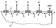
- the drawing shows a section of a sheet 1, on the front edge 2 of which the grippers 3, 3 'of a printing cylinder engage.
- the grippers 3, 3 ' are arranged at the same distance from one another and occupy 43% of the front edge of the sheet. This value has proven to be particularly favorable, since then the tensions in the arch remain small and there is sufficient freedom for the constructive design of grippers and counter grippers.
- the arrangement described on the grippers 3 results in essentially the same tensile forces P. Accordingly, the sag f of the sheet in the gripper spaces is essentially the same, so that there is no deformation of the sheet which disturbs the printing process.
- the gripper 3 ' is located at the corner 4 of the sheet 1 and thereby avoids sagging of the sheet edge.
- the gripper device according to the invention is primarily intended for use in an impression cylinder for a sheet-fed offset rotary machine. However, it can also advantageously be used in other sheet conveying systems, such as intermediate systems, take-off drums and additional systems.
Landscapes
- Supply, Installation And Extraction Of Printed Sheets Or Plates (AREA)
- Feeding Of Articles By Means Other Than Belts Or Rollers (AREA)
Abstract
Description
- Die Erfindung bezieht sich auf eine Greifervorrichtung zum Transport von Bogen an ihrer Vorderkante durch die Druckzone einer Druckmaschine mit mehreren, in einem Abstand voneinander angeordneten Greifern und Zwischenräumen zwischen den Greifern für das Heranführen von Gegengreifern bei der Bogenübergabe.
- Greifervorrichtungen der angegebenen Art sind bei Druckmaschinen allgemein bekannt. Sie haben die Aufgabe, den von einem Bogenanleger herangeführten Bogen durch die Druckmaschine zu transportieren, wobei mehrere Greifervorrichtungen zusammenwirken, die den Bogen einander übergeben. Ein richtiger und genauer Transport der Bogen durch die Greifervorrichtungen ist dabei Voraussetzung für die Erzielung einer guten Druckqualität.
- Von besonderer Bedeutung ist die Greifervorrichtung des Druckzylinders. Ihre Greifer ziehen beim Drucken den Bogen an dem Farbübertragungszylinder vorbei und nehmen dabei die Zug- kräfte auf, die durch den Farbzug und die Druckbeistellkräfte auf den Bogen einwirken. Durch den Abstand, den die einzelnen Greifer voneinander haben führen diese Kräfte zu hohen Spannungen im Bogen an den Greifereinspannstellen, während in den Zwischenräumen deutliche Spannungsanfälle festzustellen sind. Diese Spannungsunterschiede werden durch die bei den bekannten Greifervorrichtungen unterschiedlichen Greiferabstände noch erheblich verstärkt, so daß insbesondere bei dünneren Bedruckstoffen Verformungen im Boden auftreten, die zu Dupliererscheinungen führen und die Druckqualität erheblich beeinträchtigen.
- Der Erfindung liegt die Aufgabe zugrunde, eine Greifervorrichtung der eingangs genannten Art zu schaffen, die eine hohe Druckqualität gewährleistet und Dupliererscheinungen vermeidet.
- Erfindungsgemäß wird diese Aufgabe dadurch gelöst, daß der Unterschied zwischen den Abständen der einzelnen Greifer so gering ist, daß beim Durchlaufen der Druckzone der Unterschied in der Dehnung des Bogens an den Greifereinspannstellen 0,3% Dehnung nicht übersteigt. Die einspannungsbedingten Dehnungsunterschiede im Bogen werden auf diese Weise so kleir gehalten, daß nach den mit der Erfindung gewonnenen Erkenntnissen Duplieren nicht mehr auftritt. Grundlage für die Ermittlung der Greiferabstände ist dabei jeweils der dünnste bzw. weichste Bedruckstoff, der mit der Druckmaschine bedruckt werden soll. Die Erfindung hat weiterhin den Vorteil, daß durch die gleichmäßigere Verteilung der Belastung Spannungsspitzen vermieden werden und die Empfindlichkeit gegenüber Schwankungen der Festigkeit des Bedruckstoffs, die von Bogen zu Bogen auftreten können, abnimmt.
- Nach einem weiteren Vorschlag der Erfindung beträgt die Greiferbelegung der Bogenvorderkante wenigstens 40%. Durch eine derartig hohe Greiferbelegung, die durch die erfindungsgemäße Verringerung der Unterschiede zwischen den Greiferabständen ermöglicht wird, vermindert sich die Bogenbeanspruchung beim Drucken, was ebenfalls zu einer Verbesserung der Druckqualität beiträgt.
- Duplieren wird bei den bekannten Greifervorrichtungen häufig auch dadurch begünstigt, daß die Ecken des Bogens über die äußeren Greifer hinausragen und daher stark zum Durchhängen neigen. Um diesen Einfluß zu beseitigen, wird erfindungsgemäß vorgeschlagen die äußeren Greifer soweit in Richtung der Druckzylinderachse verschiebbar auszubilden, daß jeweils die Ecke der Bogen gehalten werden kann. Um die Greiferabstände in den erforderlichen Grenzen zu halten, kann es dabei zweckmäßig sein, wenn mehrere äußere Greifer verschiebbar sind.
- Die Erfindung wird anhand eines in der Zeichnung dargestellten Ausführungsbeispiels nachfolgend näher erläutert.
- Die Zeichnung zeigt einen Ausschnitt eines Bogens 1, an dessen Vorderkante 2 die Greifer 3,3' eines Druckzylinders angreifen. Die Greifer 3,3' sind im gleichen Abstand voneinander angeordnet und belegen 43% der Vorderkante des Bogens. Dieser Wert hat sich als besonders günstig erwiesen, da dann die Spannungen im Bogen klein bleiben und zur konstruktiven Gestaltung von Greifern und Gegengreifern genügend Freiraum verbleibt.
- Bei gleichmäßigem Farbzugundgleichmäßiger Druckbeistellung ergeben sich bei der beschriebenen Anordnung an den Greifern 3 im wesentlichen gleiche Zugkräfte P. Entsprechend ist auch der Durchhang f des Bogens in den Greiferzwischenräumen im wesentlichen gleich, so daß keine den Druckvorgang störende Verformung des Bogens eintritt. Der Geifer 3' befindet sich an der Ecke 4 des Bogens 1 und vermeidet dadurch einen Durchhang des Bogenrandes.
- Die erfindungsgemäße Greifervorrichtung ist hauptsächlich für die Verwendung in einem Gegendruckzylinder für eine-Bogenoffsetrotationsmaschine vorgesehen. Sie kann aber vorteilhaft auch in anderen Bogenförderungssystemen, wie Zwischensystemen, Abnahmetrommeln und Zusatzsystemen Verwendung finden.
Claims (3)
dadurch gekennzichnet,
daß der Unterschied zwischen den Abständen der einzelnen Greifer (3,3') so gering ist, daß beim Durchlaufen der Druckzone der Unterschied in der Dehnung des Bogens (1) an den Greifereinspannstellen 0,3% Dehnung nicht übersteigt.
dadurch gekennzeichnet ,
daß die Greiferbelegung der Bogenvorderkante beim Druckzylinder wenigstens 40% beträgt.
dadurch gekennzeichnet ,
daß die äußeren Greifer (3') so weit in Richtung der Druckzylinderachse verschiebbar sind, daß auch bei unter schiedlichen Bogenbreiten jeweils die Ecke (4) der Bogen (1) gehalten wird.
Priority Applications (1)
| Application Number | Priority Date | Filing Date | Title |
|---|---|---|---|
| AT85102872T ATE43293T1 (de) | 1984-05-30 | 1985-03-13 | Greifervorrichtung fuer eine druckmaschine. |
Applications Claiming Priority (2)
| Application Number | Priority Date | Filing Date | Title |
|---|---|---|---|
| DE3420177 | 1984-05-30 | ||
| DE19843420177 DE3420177A1 (de) | 1984-05-30 | 1984-05-30 | Greifervorrichtung fuer eine druckmaschine |
Publications (3)
| Publication Number | Publication Date |
|---|---|
| EP0163021A2 true EP0163021A2 (de) | 1985-12-04 |
| EP0163021A3 EP0163021A3 (en) | 1987-05-06 |
| EP0163021B1 EP0163021B1 (de) | 1989-05-24 |
Family
ID=6237226
Family Applications (1)
| Application Number | Title | Priority Date | Filing Date |
|---|---|---|---|
| EP85102872A Expired EP0163021B1 (de) | 1984-05-30 | 1985-03-13 | Greifervorrichtung für eine Druckmaschine |
Country Status (4)
| Country | Link |
|---|---|
| EP (1) | EP0163021B1 (de) |
| JP (2) | JPS60260338A (de) |
| AT (1) | ATE43293T1 (de) |
| DE (1) | DE3420177A1 (de) |
Family Cites Families (5)
| Publication number | Priority date | Publication date | Assignee | Title |
|---|---|---|---|---|
| GB577222A (en) * | 1943-02-18 | 1946-05-09 | Goss Printing Press Co Ltd | Improvements in or relating to printing press gripper mechanisms |
| JPS555225B2 (de) * | 1974-02-15 | 1980-02-05 | ||
| DE2540218A1 (de) * | 1975-09-10 | 1977-03-24 | Heidelberger Druckmasch Ag | Greifer fuer druckmaschinen |
| DD125113A1 (de) * | 1976-02-03 | 1977-04-06 | ||
| DE2924636C2 (de) * | 1979-06-19 | 1985-01-31 | M.A.N. Maschinenfabrik Augsburg-Nürnberg AG, 8900 Augsburg | Bogengreifervorrichtung für Gegendruckzylinder und Übergabetrommeln von Bogen-Rotationsdruckmaschinen |
-
1984
- 1984-05-30 DE DE19843420177 patent/DE3420177A1/de not_active Ceased
-
1985
- 1985-03-13 AT AT85102872T patent/ATE43293T1/de active
- 1985-03-13 EP EP85102872A patent/EP0163021B1/de not_active Expired
- 1985-05-30 JP JP60115549A patent/JPS60260338A/ja active Pending
-
1993
- 1993-10-29 JP JP1993058599U patent/JPH0711974Y2/ja not_active Expired - Lifetime
Also Published As
| Publication number | Publication date |
|---|---|
| JPH0711974Y2 (ja) | 1995-03-22 |
| DE3420177A1 (de) | 1985-12-05 |
| JPS60260338A (ja) | 1985-12-23 |
| EP0163021A3 (en) | 1987-05-06 |
| JPH0645734U (ja) | 1994-06-21 |
| EP0163021B1 (de) | 1989-05-24 |
| ATE43293T1 (de) | 1989-06-15 |
Similar Documents
| Publication | Publication Date | Title |
|---|---|---|
| DE69904995T2 (de) | Beschichtungssytem für bogenartiges Material | |
| EP0161522B1 (de) | Bogen-Rotationsdruckmaschine für einseitigen Mehrfarbendruck oder Schön- und Widerdruck | |
| DE4213024B4 (de) | Bogendruckmaschine | |
| EP0158816B1 (de) | Bogen-Rotationsdruckmaschine zur Herstellung von einseitigem Mehrfarbendruck oder Schön- und Widerdruck | |
| EP0280957B1 (de) | Farbwerk für eine Rotations-Offsetdruckmaschine | |
| DE4422390B4 (de) | Doppelseiten-Bogen-Rotationsoffsetpresse | |
| DE19617744A1 (de) | Einrichtung zum Wechseln von Druckformen an Druckwerken von Druckmaschinen | |
| DE4228610B4 (de) | Papierführung bei Rollenrotationsdruckmaschinen | |
| EP2197679A1 (de) | Druckwerk, druckmaschine sowie verfahren zum betreiben eines druckwerks | |
| DE3034212A1 (de) | Rotationsdruckmaschine mit einer bogenstapelmarkierungsvorrichtung | |
| DE8901222U1 (de) | Bogen-Rotationsdruckmaschine für einseitigen Mehrfarbendruck | |
| EP0150355B1 (de) | Verfahren zum Schön- und Widerdruck, sowie Bogen-Offset-Druckmaschine zur Durchführung des Verfahrens | |
| DE3040388A1 (de) | Bogenoffsetdruckmaschine mit mindestens einem druckwerk fuer schoen- und widerdruck | |
| CH651501A5 (en) | Sheet-fed rotary printing machine having at least one printing unit | |
| EP0163021B1 (de) | Greifervorrichtung für eine Druckmaschine | |
| CH651500A5 (en) | Sheet-fed rotary printing machine having at least one printing unit | |
| DE8416548U1 (de) | Greifervorrichtung für eine Druckmaschine | |
| DE3014144C2 (de) | Vorrichtung zum Aufbringen einer Flüssigkeit auf den Plattenzylinder einer Rotationsdruckmaschine | |
| DE3211454C2 (de) | Rollenrotationsdruckmaschine für Endlosdruck | |
| CH649033A5 (en) | Sheet-fed offset rotary printing machine | |
| DE10258855B4 (de) | Bogentransferzylinder | |
| EP0765746B1 (de) | Druckmaschine und Verfahren zum Bogentransport entlang mehrerer Formzylinder | |
| EP0132799B1 (de) | Bogenrotationsdruckmaschine in Reihenbauweise | |
| EP1688251A2 (de) | Druckwerk einer Druckmaschine | |
| DE8028547U1 (de) | Bogenoffset-Rotationsdruckmaschine mit mindestens einem Druckwerk für Schön- und Widerdruck |
Legal Events
| Date | Code | Title | Description |
|---|---|---|---|
| PUAI | Public reference made under article 153(3) epc to a published international application that has entered the european phase |
Free format text: ORIGINAL CODE: 0009012 |
|
| AK | Designated contracting states |
Designated state(s): AT CH FR GB IT LI NL SE |
|
| PUAL | Search report despatched |
Free format text: ORIGINAL CODE: 0009013 |
|
| AK | Designated contracting states |
Kind code of ref document: A3 Designated state(s): AT CH FR GB IT LI NL SE |
|
| 17P | Request for examination filed |
Effective date: 19870505 |
|
| 17Q | First examination report despatched |
Effective date: 19880315 |
|
| ITF | It: translation for a ep patent filed | ||
| GRAA | (expected) grant |
Free format text: ORIGINAL CODE: 0009210 |
|
| AK | Designated contracting states |
Kind code of ref document: B1 Designated state(s): AT CH FR GB IT LI NL SE |
|
| REF | Corresponds to: |
Ref document number: 43293 Country of ref document: AT Date of ref document: 19890615 Kind code of ref document: T |
|
| ET | Fr: translation filed | ||
| GBT | Gb: translation of ep patent filed (gb section 77(6)(a)/1977) | ||
| PLBE | No opposition filed within time limit |
Free format text: ORIGINAL CODE: 0009261 |
|
| STAA | Information on the status of an ep patent application or granted ep patent |
Free format text: STATUS: NO OPPOSITION FILED WITHIN TIME LIMIT |
|
| 26N | No opposition filed | ||
| ITTA | It: last paid annual fee | ||
| EAL | Se: european patent in force in sweden |
Ref document number: 85102872.0 |
|
| PGFP | Annual fee paid to national office [announced via postgrant information from national office to epo] |
Ref country code: CH Payment date: 19950213 Year of fee payment: 11 |
|
| PGFP | Annual fee paid to national office [announced via postgrant information from national office to epo] |
Ref country code: SE Payment date: 19960219 Year of fee payment: 12 |
|
| PGFP | Annual fee paid to national office [announced via postgrant information from national office to epo] |
Ref country code: NL Payment date: 19960222 Year of fee payment: 12 |
|
| PG25 | Lapsed in a contracting state [announced via postgrant information from national office to epo] |
Ref country code: LI Effective date: 19960331 Ref country code: CH Effective date: 19960331 |
|
| PG25 | Lapsed in a contracting state [announced via postgrant information from national office to epo] |
Ref country code: NL Effective date: 19961001 |
|
| REG | Reference to a national code |
Ref country code: CH Ref legal event code: PL |
|
| NLV4 | Nl: lapsed or anulled due to non-payment of the annual fee |
Effective date: 19961001 |
|
| PG25 | Lapsed in a contracting state [announced via postgrant information from national office to epo] |
Ref country code: SE Effective date: 19970314 |
|
| EUG | Se: european patent has lapsed |
Ref document number: 85102872.0 |
|
| PGFP | Annual fee paid to national office [announced via postgrant information from national office to epo] |
Ref country code: AT Payment date: 20000224 Year of fee payment: 16 |
|
| PGFP | Annual fee paid to national office [announced via postgrant information from national office to epo] |
Ref country code: GB Payment date: 20010214 Year of fee payment: 17 |
|
| PG25 | Lapsed in a contracting state [announced via postgrant information from national office to epo] |
Ref country code: AT Free format text: LAPSE BECAUSE OF NON-PAYMENT OF DUE FEES Effective date: 20010313 |
|
| PGFP | Annual fee paid to national office [announced via postgrant information from national office to epo] |
Ref country code: FR Payment date: 20010313 Year of fee payment: 17 |
|
| REG | Reference to a national code |
Ref country code: GB Ref legal event code: IF02 |
|
| PG25 | Lapsed in a contracting state [announced via postgrant information from national office to epo] |
Ref country code: GB Free format text: LAPSE BECAUSE OF NON-PAYMENT OF DUE FEES Effective date: 20020313 |
|
| GBPC | Gb: european patent ceased through non-payment of renewal fee |
Effective date: 20020313 |
|
| PG25 | Lapsed in a contracting state [announced via postgrant information from national office to epo] |
Ref country code: FR Free format text: LAPSE BECAUSE OF NON-PAYMENT OF DUE FEES Effective date: 20021129 |
|
| REG | Reference to a national code |
Ref country code: FR Ref legal event code: ST |