EP0163037A2 - Dispositif de dosage - Google Patents
Dispositif de dosage Download PDFInfo
- Publication number
- EP0163037A2 EP0163037A2 EP85103467A EP85103467A EP0163037A2 EP 0163037 A2 EP0163037 A2 EP 0163037A2 EP 85103467 A EP85103467 A EP 85103467A EP 85103467 A EP85103467 A EP 85103467A EP 0163037 A2 EP0163037 A2 EP 0163037A2
- Authority
- EP
- European Patent Office
- Prior art keywords
- metering
- metering device
- piston
- dosing
- gravimetric
- Prior art date
- Legal status (The legal status is an assumption and is not a legal conclusion. Google has not performed a legal analysis and makes no representation as to the accuracy of the status listed.)
- Granted
Links
Images
Classifications
-
- G—PHYSICS
- G05—CONTROLLING; REGULATING
- G05D—SYSTEMS FOR CONTROLLING OR REGULATING NON-ELECTRIC VARIABLES
- G05D11/00—Control of flow ratio
-
- B—PERFORMING OPERATIONS; TRANSPORTING
- B01—PHYSICAL OR CHEMICAL PROCESSES OR APPARATUS IN GENERAL
- B01F—MIXING, e.g. DISSOLVING, EMULSIFYING OR DISPERSING
- B01F35/00—Accessories for mixers; Auxiliary operations or auxiliary devices; Parts or details of general application
- B01F35/80—Forming a predetermined ratio of the substances to be mixed
- B01F35/88—Forming a predetermined ratio of the substances to be mixed by feeding the materials batchwise
- B01F35/881—Forming a predetermined ratio of the substances to be mixed by feeding the materials batchwise by weighing, e.g. with automatic discharge
-
- B—PERFORMING OPERATIONS; TRANSPORTING
- B01—PHYSICAL OR CHEMICAL PROCESSES OR APPARATUS IN GENERAL
- B01F—MIXING, e.g. DISSOLVING, EMULSIFYING OR DISPERSING
- B01F35/00—Accessories for mixers; Auxiliary operations or auxiliary devices; Parts or details of general application
- B01F35/80—Forming a predetermined ratio of the substances to be mixed
- B01F35/88—Forming a predetermined ratio of the substances to be mixed by feeding the materials batchwise
- B01F35/882—Forming a predetermined ratio of the substances to be mixed by feeding the materials batchwise using measuring chambers, e.g. volumetric pumps, for feeding the substances
- B01F35/8822—Forming a predetermined ratio of the substances to be mixed by feeding the materials batchwise using measuring chambers, e.g. volumetric pumps, for feeding the substances using measuring chambers of the piston or plunger type
-
- G—PHYSICS
- G05—CONTROLLING; REGULATING
- G05D—SYSTEMS FOR CONTROLLING OR REGULATING NON-ELECTRIC VARIABLES
- G05D11/00—Control of flow ratio
- G05D11/02—Controlling ratio of two or more flows of fluid or fluent material
- G05D11/035—Controlling ratio of two or more flows of fluid or fluent material with auxiliary non-electric power
- G05D11/04—Controlling ratio of two or more flows of fluid or fluent material with auxiliary non-electric power by sensing weight of individual components, e.g. gravimetric procedure
-
- B—PERFORMING OPERATIONS; TRANSPORTING
- B29—WORKING OF PLASTICS; WORKING OF SUBSTANCES IN A PLASTIC STATE IN GENERAL
- B29B—PREPARATION OR PRETREATMENT OF THE MATERIAL TO BE SHAPED; MAKING GRANULES OR PREFORMS; RECOVERY OF PLASTICS OR OTHER CONSTITUENTS OF WASTE MATERIAL CONTAINING PLASTICS
- B29B7/00—Mixing; Kneading
- B29B7/02—Mixing; Kneading non-continuous, with mechanical mixing or kneading devices, i.e. batch type
- B29B7/22—Component parts, details or accessories; Auxiliary operations
- B29B7/24—Component parts, details or accessories; Auxiliary operations for feeding
-
- B—PERFORMING OPERATIONS; TRANSPORTING
- B29—WORKING OF PLASTICS; WORKING OF SUBSTANCES IN A PLASTIC STATE IN GENERAL
- B29B—PREPARATION OR PRETREATMENT OF THE MATERIAL TO BE SHAPED; MAKING GRANULES OR PREFORMS; RECOVERY OF PLASTICS OR OTHER CONSTITUENTS OF WASTE MATERIAL CONTAINING PLASTICS
- B29B7/00—Mixing; Kneading
- B29B7/30—Mixing; Kneading continuous, with mechanical mixing or kneading devices
- B29B7/58—Component parts, details or accessories; Auxiliary operations
- B29B7/60—Component parts, details or accessories; Auxiliary operations for feeding, e.g. end guides for the incoming material
Definitions
- the invention relates to a dosing device for liquids and pastes for the production of material mixtures from different components, wherein each component can be gravimetrically fed to a mixing container from a supply container via a material feed with a dosing unit and a material inlet opening of the dosing unit can be controlled via a filling valve by the amount supplied Can be recorded on a scale and adjusted by a control unit via the filling valve.
- Devices of this type are known per se and are used for batches in the 100 to 1000 kg range, an appropriately large scale having to be selected.
- main components can be dosed very well and quickly; however, small components required in a mixture can no longer be detected since the accuracy of the balance does not allow this.
- the object of the invention is to improve the known arrangements to provide a simple and compact metering device which enables metering of components of different sizes with the required accuracy with a metering unit and thereby ensures the supply of components optionally according to the different mixtures.
- each metering unit has a volumetric piston metering device for small metered quantities with a material inlet opening controlled by an ejection valve and the metered amount is adjustable by the control unit and in that a common material supply for the volumetric metering device is arranged.
- the common material supply be formed from a ring line with an inlet and an outlet.
- the drive elements for the piston metering device and the gravimetric metering device can be controlled via adjusting elements with switching stages for the different speeds or for coarse / fine flow metering.
- the piston stroke of the piston metering device can be set as a partial stroke via a scanning control acting on the piston rod.
- a scanning control acting on the piston rod.
- the scanning control is formed by a sleeve with grooves on the piston rod and a fixed inductive proximity switch.
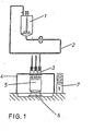
- the arrangement shown consists of supply containers 1 for each component, which is connected to an associated metering unit 3 via a material feed 2.
- individual dosing units 3 are arranged in parallel above a mixing container 5 via a holding device 4.
- the mixing container 5 is received by a scale 6, which controls the part of the metering unit 3 for the gravimetric feed via a central control unit 7.
- the control unit 7 is also used for the pre-programming of the desired mixture.
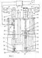
- the metering unit 3 is essentially formed from a housing block 8, which is provided with an inlet 9 and receives a piston metering system for small components and a gravimetric metering device for large components.
- the inlet 9 branches out as a material feed for both systems.
- the gravimetric metering device is formed by a metering valve which is closed at the top by a cover flange 10.
- a plate 12 is inserted, which is connected to a bellows 13 in a liquid-tight manner. With its other end, the bellows 13 is fastened to a valve cone 14 and enables the lifting movement of the valve cone 14 with a maintenance-free sealing of a piston rod 15 to the outside.
- the actual valve is formed from the valve cone 14 with an associated valve seat 16, which is located in a lower end plate 17 and is connected to the underside of the housing 8.
- a pneumatic cylinder 18 is mounted on a support plate 19 provided for this purpose.
- the pneumatic cylinder 18 is provided in this case for 2-stage operation, ie via ent speaking controls by means of 3/2-way solenoid valve 20 or 21, valve 14, 16 is opened completely or only partially (coarse flow / fine flow metering).
- the pneumatic cylinder 18 has a knurled adjusting screw 22 on its upper end face, with which the opening width can be infinitely adjusted in the “fine metering” control.
- the valve 14, 16 is closed by a closing spring 23 built into the bellows 13.
- the quantities are controlled via the scale 6, which executes the commands for the valves 20, 21 in a known manner via the control unit 7.
- the parallel piston metering system for volumetric metering is formed by a cylinder tube 24 and a matching piston 25.
- the metering is achieved in that the piston 25 is in the upper position in the cylinder tube 24 and thus releases a metering bore of the cylinder tube 24. Since the cylinder tube 24 is completely filled with the supplied product in the upper region via the inlet 9, the product flows into the metering hole when the metering hole becomes free and fills it completely. After reaching the top dead center, the piston 25 moves down again, dips into the metering bore and, from the point of immersion in the bore, presses the product therein downward through a discharge valve 26, 27.
- the discharge valve 26, 27 closes at the moment by the force of a closing spring 38, in that the piston 25 reaches bottom dead center and no longer displaces any product.
- the discharge valve 26, 27 seals.
- the valve seat 27 is arranged in a lower end plate 28 on the housing 8.
- the up and down movement of the piston 25 is caused by a compressed air cylinder 29 on the support plate 12.
- This compressed air cylinder 29 is controlled in parallel via two 3/2-way solenoid valves 30, 31 in order to have the different air throughput rates and thus the piston metering device with two different speeds, namely a quick metering device and a fine metering device depending on the control of one or the other valve 30 or .31 is operated.
- the piston is sealed at the top in the housing by an upper end plate 32 with inserted sealing rings.
- an immersion tube 33 is fastened, through which the piston 25 is passed.
- the immersion tube 33 is filled with a rinsing liquid which has the purpose of preventing a product film from drying on the piston 25, since, depending on the nature of the product, a product film which has dried on after a long period of inactivity of the device can destroy the piston seals.
- a device is attached to the piston rod 34, which device enables the metering stroke of the piston rod 34 to be broken down into a number of sub-steps via an inductive tap.
- the number of steps depends on the impulse teeth on the device.
- the device consists of a sleeve 35 with a certain number of grooves 36 or a toothed rack, the grooves or teeth of which, when the piston 25 is moved, are tapped off by an inductive proximity switch 37, which is attached to a bracket on the housing 8 of the metering device an electronic counter of the control unit 7 are forwarded for evaluation.
- This special device makes it possible not only to perform entire strokes, but also partial strokes for the metering in accordance with the selected division of the sleeve 35 or toothed rack. For the dosing task, not whole strokes but rather the desired number of partial strokes are given by impulses.
- control unit 7 which contains appropriate programs, to produce mixtures which contain both large components and small components and which can also be used to carry out a changing setting in accordance with the different requirements.
- the material feed 9 serves as an inlet and is provided as a ring line with an outlet 36 as a backwash line.
- the supplied material is first passed through the chamber of the piston metering system and from there through the volumetric metering system in order to process products that tend to sediment.
- the assignment of the controller can also be seen from this representation.
Landscapes
- Engineering & Computer Science (AREA)
- Chemical Kinetics & Catalysis (AREA)
- Physics & Mathematics (AREA)
- General Physics & Mathematics (AREA)
- Automation & Control Theory (AREA)
- Chemical & Material Sciences (AREA)
- Power Engineering (AREA)
- Accessories For Mixers (AREA)
- Electrical Discharge Machining, Electrochemical Machining, And Combined Machining (AREA)
- Paper (AREA)
- Basic Packing Technique (AREA)
- Pharmaceuticals Containing Other Organic And Inorganic Compounds (AREA)
- Processing And Handling Of Plastics And Other Materials For Molding In General (AREA)
Priority Applications (1)
| Application Number | Priority Date | Filing Date | Title |
|---|---|---|---|
| AT85103467T ATE50651T1 (de) | 1984-05-25 | 1985-03-23 | Dosiervorrichtung. |
Applications Claiming Priority (2)
| Application Number | Priority Date | Filing Date | Title |
|---|---|---|---|
| DE3419485 | 1984-05-25 | ||
| DE19843419485 DE3419485A1 (de) | 1984-05-25 | 1984-05-25 | Dosiervorrichtung |
Publications (3)
| Publication Number | Publication Date |
|---|---|
| EP0163037A2 true EP0163037A2 (fr) | 1985-12-04 |
| EP0163037A3 EP0163037A3 (en) | 1986-09-03 |
| EP0163037B1 EP0163037B1 (fr) | 1990-02-28 |
Family
ID=6236801
Family Applications (1)
| Application Number | Title | Priority Date | Filing Date |
|---|---|---|---|
| EP85103467A Expired - Lifetime EP0163037B1 (fr) | 1984-05-25 | 1985-03-23 | Dispositif de dosage |
Country Status (3)
| Country | Link |
|---|---|
| EP (1) | EP0163037B1 (fr) |
| AT (1) | ATE50651T1 (fr) |
| DE (2) | DE3419485A1 (fr) |
Cited By (4)
| Publication number | Priority date | Publication date | Assignee | Title |
|---|---|---|---|---|
| FR2625806A1 (fr) * | 1988-01-11 | 1989-07-13 | Perquis Vincent | Dispositif pour doser par pesee des produits contenus dans des boites |
| FR2631855A1 (fr) * | 1988-05-31 | 1989-12-01 | Wenmaekers Monique | Fabrication en continu d'une emulsion par quantites discretes |
| WO1998028069A1 (fr) * | 1996-12-23 | 1998-07-02 | Deutsche Amphibolin-Werke Von Robert Murjahn Gmbh & Co. Kg | Systeme de dosage et de nuançage |
| ES2173040A1 (es) * | 2001-01-23 | 2002-10-01 | Univ La Rioja | Sistema automatico de dosificacion homogenea de sulfuroso en bodegas. |
Families Citing this family (3)
| Publication number | Priority date | Publication date | Assignee | Title |
|---|---|---|---|---|
| NO954406L (no) * | 1995-03-01 | 1996-09-02 | Torbjoern Randsborg | Anordning ved blandemaskin, spesielt for blanding av trykk-farge |
| GB9923280D0 (en) | 1999-10-01 | 1999-12-08 | Unilever Plc | Fabric care composition |
| DE10159272A1 (de) * | 2001-12-03 | 2003-06-12 | Bayer Ag | Verfahren und Vorrichtung zur Dosierung von Flüssigkeiten |
Family Cites Families (6)
| Publication number | Priority date | Publication date | Assignee | Title |
|---|---|---|---|---|
| DE2805946A1 (de) * | 1978-02-13 | 1979-08-16 | Bayer Ag | Vorrichtung zum dosieren mindestens zweier fliessfaehiger reaktionskomponenten in eine mischkammer |
| CH636702A5 (en) * | 1978-06-30 | 1983-06-15 | Stoecklin Walter Ag | Process and device for metering liquid and pasty media, in particular colorants |
| US4228924A (en) * | 1978-08-23 | 1980-10-21 | Gilbert Charles H | Mixture metering machine |
| CH642744A5 (en) * | 1981-07-29 | 1984-04-30 | Dec Engineering Sa | Method for metering a mixture |
| DE3201221A1 (de) * | 1982-01-16 | 1983-07-28 | Walter 4600 Dortmund Ribic | Station zum anmischen insbesondere von farben und dergleichen |
| DE3411155C2 (de) * | 1984-03-27 | 1986-01-23 | Abel Gmbh & Co Pumpen Und Maschinenbau, 4300 Essen | Abfüllanlage zum Abfüllen von Flüssigkeiten in Gebinde, insbesondere zum Abfüllen von Mineralöl |
-
1984
- 1984-05-25 DE DE19843419485 patent/DE3419485A1/de not_active Withdrawn
-
1985
- 1985-03-23 EP EP85103467A patent/EP0163037B1/fr not_active Expired - Lifetime
- 1985-03-23 AT AT85103467T patent/ATE50651T1/de not_active IP Right Cessation
- 1985-03-23 DE DE8585103467T patent/DE3576227D1/de not_active Expired - Fee Related
Cited By (6)
| Publication number | Priority date | Publication date | Assignee | Title |
|---|---|---|---|---|
| FR2625806A1 (fr) * | 1988-01-11 | 1989-07-13 | Perquis Vincent | Dispositif pour doser par pesee des produits contenus dans des boites |
| FR2631855A1 (fr) * | 1988-05-31 | 1989-12-01 | Wenmaekers Monique | Fabrication en continu d'une emulsion par quantites discretes |
| EP0345135A1 (fr) * | 1988-05-31 | 1989-12-06 | Monique Wenmaekers | Fabrication en continu d'une émulsion par quantités discrètes |
| US5073031A (en) * | 1988-05-31 | 1991-12-17 | Monique Wenmaekers | Continuous manufacture of an emulsion in discrete quantities |
| WO1998028069A1 (fr) * | 1996-12-23 | 1998-07-02 | Deutsche Amphibolin-Werke Von Robert Murjahn Gmbh & Co. Kg | Systeme de dosage et de nuançage |
| ES2173040A1 (es) * | 2001-01-23 | 2002-10-01 | Univ La Rioja | Sistema automatico de dosificacion homogenea de sulfuroso en bodegas. |
Also Published As
| Publication number | Publication date |
|---|---|
| ATE50651T1 (de) | 1990-03-15 |
| EP0163037B1 (fr) | 1990-02-28 |
| EP0163037A3 (en) | 1986-09-03 |
| DE3419485A1 (de) | 1985-11-28 |
| DE3576227D1 (de) | 1990-04-05 |
Similar Documents
| Publication | Publication Date | Title |
|---|---|---|
| EP0450377B1 (fr) | Appareil pour le remplissage de récipients avec un liquide | |
| DE2641549A1 (de) | Steuer- und abfuelleinrichtung fuer abfuellmaschinen | |
| EP0163037B1 (fr) | Dispositif de dosage | |
| DE1952061A1 (de) | Mischungs- und Ausgabeeinheit | |
| DE2402213A1 (de) | Messvorrichtung | |
| DE2002060A1 (de) | Fuellrohrloses Fuellelement fuer Gegendruck-Fuellmaschinen in Ein- oder Mehrkammer-Bauweise | |
| DE1573126A1 (de) | Vorrichtung zum Abmessen und Vermischen von trockenen,gekoernten Materialien | |
| DE3629421C1 (de) | Verfahren und Vorrichtung zum Zufuehren von Mahlkoerpern | |
| CH637032A5 (de) | Vorrichtung zum mischen mehrerer fliessfaehiger medien. | |
| DE2914750C2 (fr) | ||
| EP0019052B1 (fr) | Dispositif de prélévement d'échantillons de matières plastiques semi-liquides dans un récipient | |
| EP0107808A2 (fr) | Dispositif pour fournir des matériaux épais en quantités dosées | |
| DE3421581C2 (fr) | ||
| DE4324799A1 (de) | Vorrichtung zum Abfüllen von Flüssigkeiten in Flaschen, Dosen, oder dergleichen Behälter | |
| EP0016412B1 (fr) | Valve à commande pneumatique | |
| DE3240991A1 (de) | Vorrichtung zum gleichzeitigen abfuellen von fluessigkeiten in mehrere behaelter | |
| CH684850A5 (de) | Dosiereinrichtung für Flüssigkeiten. | |
| DE4344922C3 (de) | Vorrichtung zum Befüllen einer oder mehrerer Gießformen mit gießfähig flüssigen Medien | |
| DE2523918A1 (de) | Vorrichtung zum dosieren und mischen von kosmetikprodukten | |
| DE3436102A1 (de) | Mehrkomponenten proportionieranlage | |
| DE1918425A1 (de) | Expresskaffeemaschine | |
| DE1094662B (de) | Vorrichtung zum Beschicken einer pneumatischen oder hydraulischen Foerderleitung mitfliessfaehigem Material | |
| DE19845702C2 (de) | Rühr- und Mischeinrichtung für einen Vorratsbehälter mit Dosiereinrichtung für zähflüssige Stoffe, wie Gießharz | |
| DE3921792C1 (fr) | ||
| AT393495B (de) | Dosierventil, insbesondere zur abgabe von getraenkekonzentraten in getraenkeautomaten |
Legal Events
| Date | Code | Title | Description |
|---|---|---|---|
| PUAI | Public reference made under article 153(3) epc to a published international application that has entered the european phase |
Free format text: ORIGINAL CODE: 0009012 |
|
| AK | Designated contracting states |
Designated state(s): AT BE CH DE FR GB LI NL |
|
| PUAL | Search report despatched |
Free format text: ORIGINAL CODE: 0009013 |
|
| AK | Designated contracting states |
Kind code of ref document: A3 Designated state(s): AT BE CH DE FR GB LI NL |
|
| 17P | Request for examination filed |
Effective date: 19870207 |
|
| 17Q | First examination report despatched |
Effective date: 19880610 |
|
| GRAA | (expected) grant |
Free format text: ORIGINAL CODE: 0009210 |
|
| AK | Designated contracting states |
Kind code of ref document: B1 Designated state(s): AT BE CH DE FR GB LI NL |
|
| REF | Corresponds to: |
Ref document number: 50651 Country of ref document: AT Date of ref document: 19900315 Kind code of ref document: T |
|
| REF | Corresponds to: |
Ref document number: 3576227 Country of ref document: DE Date of ref document: 19900405 |
|
| ET | Fr: translation filed | ||
| GBT | Gb: translation of ep patent filed (gb section 77(6)(a)/1977) | ||
| PLBE | No opposition filed within time limit |
Free format text: ORIGINAL CODE: 0009261 |
|
| STAA | Information on the status of an ep patent application or granted ep patent |
Free format text: STATUS: NO OPPOSITION FILED WITHIN TIME LIMIT |
|
| 26N | No opposition filed | ||
| PGFP | Annual fee paid to national office [announced via postgrant information from national office to epo] |
Ref country code: LU Payment date: 19940228 Year of fee payment: 10 |
|
| EPTA | Lu: last paid annual fee | ||
| PGFP | Annual fee paid to national office [announced via postgrant information from national office to epo] |
Ref country code: BE Payment date: 19950504 Year of fee payment: 11 |
|
| PG25 | Lapsed in a contracting state [announced via postgrant information from national office to epo] |
Ref country code: BE Effective date: 19960331 |
|
| BERE | Be: lapsed |
Owner name: FECO-INDUSTRIEANLAGENBAU G.M.B.H. Effective date: 19960331 |
|
| PGFP | Annual fee paid to national office [announced via postgrant information from national office to epo] |
Ref country code: GB Payment date: 19980312 Year of fee payment: 14 |
|
| PGFP | Annual fee paid to national office [announced via postgrant information from national office to epo] |
Ref country code: FR Payment date: 19980324 Year of fee payment: 14 |
|
| PGFP | Annual fee paid to national office [announced via postgrant information from national office to epo] |
Ref country code: NL Payment date: 19980331 Year of fee payment: 14 Ref country code: AT Payment date: 19980331 Year of fee payment: 14 |
|
| PGFP | Annual fee paid to national office [announced via postgrant information from national office to epo] |
Ref country code: CH Payment date: 19980522 Year of fee payment: 14 |
|
| PG25 | Lapsed in a contracting state [announced via postgrant information from national office to epo] |
Ref country code: GB Free format text: LAPSE BECAUSE OF NON-PAYMENT OF DUE FEES Effective date: 19990323 Ref country code: AT Free format text: LAPSE BECAUSE OF NON-PAYMENT OF DUE FEES Effective date: 19990323 |
|
| PG25 | Lapsed in a contracting state [announced via postgrant information from national office to epo] |
Ref country code: LI Free format text: LAPSE BECAUSE OF NON-PAYMENT OF DUE FEES Effective date: 19990331 Ref country code: CH Free format text: LAPSE BECAUSE OF NON-PAYMENT OF DUE FEES Effective date: 19990331 |
|
| PGFP | Annual fee paid to national office [announced via postgrant information from national office to epo] |
Ref country code: DE Payment date: 19990525 Year of fee payment: 15 |
|
| PG25 | Lapsed in a contracting state [announced via postgrant information from national office to epo] |
Ref country code: NL Free format text: LAPSE BECAUSE OF NON-PAYMENT OF DUE FEES Effective date: 19991001 |
|
| GBPC | Gb: european patent ceased through non-payment of renewal fee |
Effective date: 19990323 |
|
| REG | Reference to a national code |
Ref country code: CH Ref legal event code: PL |
|
| PG25 | Lapsed in a contracting state [announced via postgrant information from national office to epo] |
Ref country code: FR Free format text: LAPSE BECAUSE OF NON-PAYMENT OF DUE FEES Effective date: 19991130 |
|
| NLV4 | Nl: lapsed or anulled due to non-payment of the annual fee |
Effective date: 19991001 |
|
| REG | Reference to a national code |
Ref country code: FR Ref legal event code: ST |
|
| PG25 | Lapsed in a contracting state [announced via postgrant information from national office to epo] |
Ref country code: DE Free format text: LAPSE BECAUSE OF NON-PAYMENT OF DUE FEES Effective date: 20010103 |