EP0163078A1 - Soupape de refoulement - Google Patents
Soupape de refoulement Download PDFInfo
- Publication number
- EP0163078A1 EP0163078A1 EP85104323A EP85104323A EP0163078A1 EP 0163078 A1 EP0163078 A1 EP 0163078A1 EP 85104323 A EP85104323 A EP 85104323A EP 85104323 A EP85104323 A EP 85104323A EP 0163078 A1 EP0163078 A1 EP 0163078A1
- Authority
- EP
- European Patent Office
- Prior art keywords
- valve
- pressure
- injection
- pressure valve
- throttle
- Prior art date
- Legal status (The legal status is an assumption and is not a legal conclusion. Google has not performed a legal analysis and makes no representation as to the accuracy of the status listed.)
- Granted
Links
- 238000002347 injection Methods 0.000 claims abstract description 74
- 239000007924 injection Substances 0.000 claims abstract description 74
- 239000000446 fuel Substances 0.000 claims abstract description 53
- 238000007789 sealing Methods 0.000 claims abstract description 8
- 238000002485 combustion reaction Methods 0.000 claims description 14
- 230000006835 compression Effects 0.000 claims 2
- 238000007906 compression Methods 0.000 claims 2
- 238000009434 installation Methods 0.000 claims 1
- 230000000694 effects Effects 0.000 description 11
- 239000007788 liquid Substances 0.000 description 5
- 239000007921 spray Substances 0.000 description 5
- 230000009747 swallowing Effects 0.000 description 5
- 230000006399 behavior Effects 0.000 description 3
- 238000005507 spraying Methods 0.000 description 2
- 238000004939 coking Methods 0.000 description 1
- 230000003111 delayed effect Effects 0.000 description 1
- 210000002445 nipple Anatomy 0.000 description 1
- 230000000391 smoking effect Effects 0.000 description 1
- 239000000243 solution Substances 0.000 description 1
- 238000011144 upstream manufacturing Methods 0.000 description 1
Images
Classifications
-
- F—MECHANICAL ENGINEERING; LIGHTING; HEATING; WEAPONS; BLASTING
- F02—COMBUSTION ENGINES; HOT-GAS OR COMBUSTION-PRODUCT ENGINE PLANTS
- F02M—SUPPLYING COMBUSTION ENGINES IN GENERAL WITH COMBUSTIBLE MIXTURES OR CONSTITUENTS THEREOF
- F02M55/00—Fuel-injection apparatus characterised by their fuel conduits or their venting means; Arrangements of conduits between fuel tank and pump F02M37/00
- F02M55/02—Conduits between injection pumps and injectors, e.g. conduits between pump and common-rail or conduits between common-rail and injectors
-
- F—MECHANICAL ENGINEERING; LIGHTING; HEATING; WEAPONS; BLASTING
- F02—COMBUSTION ENGINES; HOT-GAS OR COMBUSTION-PRODUCT ENGINE PLANTS
- F02M—SUPPLYING COMBUSTION ENGINES IN GENERAL WITH COMBUSTIBLE MIXTURES OR CONSTITUENTS THEREOF
- F02M59/00—Pumps specially adapted for fuel-injection and not provided for in groups F02M39/00 -F02M57/00, e.g. rotary cylinder-block type of pumps
- F02M59/44—Details, components parts, or accessories not provided for in, or of interest apart from, the apparatus of groups F02M59/02 - F02M59/42; Pumps having transducers, e.g. to measure displacement of pump rack or piston
- F02M59/46—Valves
- F02M59/462—Delivery valves
-
- Y—GENERAL TAGGING OF NEW TECHNOLOGICAL DEVELOPMENTS; GENERAL TAGGING OF CROSS-SECTIONAL TECHNOLOGIES SPANNING OVER SEVERAL SECTIONS OF THE IPC; TECHNICAL SUBJECTS COVERED BY FORMER USPC CROSS-REFERENCE ART COLLECTIONS [XRACs] AND DIGESTS
- Y10—TECHNICAL SUBJECTS COVERED BY FORMER USPC
- Y10T—TECHNICAL SUBJECTS COVERED BY FORMER US CLASSIFICATION
- Y10T137/00—Fluid handling
- Y10T137/7722—Line condition change responsive valves
- Y10T137/7771—Bi-directional flow valves
- Y10T137/7772—One head and seat carried by head of another
- Y10T137/7774—Supporting valve spring carried by supporting valve
Definitions
- the invention is based on a pressure valve according to the preamble of the main claim.
- a pressure valve known from CH-PS 394 710
- the so-called dripping or re-injection of fuel after the effective delivery stroke of the injection pump piston is to be prevented by providing a return suction collar on the pressure valve in combination with a relief throttle possibly controlled by a pressure-maintaining valve.
- pressure waves would occur in the fuel delivery line between the pressure valve and the injection valve, which would reciprocate between the injection valve and the pressure valve.
- the returning waves reflected from the pressure valve to the injection valve can subsequently open it, so that fuel leaks occur with the known disadvantages.
- the known configuration has only the purpose of preventing the injection or dripping, namely in a wide range of the injection quantity control per injection stroke.
- the relief throttle which is not controlled by a pressure control valve, has the effect that the residual pressure in the fuel delivery line changes greatly with the speed.
- the delivery line between pressure valve and injection valve is relieved in the same way as with large injection quantities.
- a more or less large swallowing volume is effective, which has to be filled up by the pump piston delivery until the injection pressure at the injection valve is reached.
- this disadvantageously leads to noticeable quantity spreads due to the different best pressures, which have a disadvantageous effect on the running behavior of the internal combustion engine.
- part of the useful stroke of the pump piston is lost.
- the throttle connection on the valve closing member of the pressure valve is then intended to prevent the valve closing member from lifting during ignition fuel injection by the amount that would correspond to the relief volume without the throttle. This is to prevent the fuel delivery line from being relieved by the full amount of the relief volume made available by the relief association at the end of the spray. This relief would lead to an unsatisfactory operating result.
- the throttle connection is intended to switch off the discharge completely in the operating range in which ignition fuel is to be injected, in that the quantity of ignition fuel flows past the relief collar via the throttle connection without a noticeable pressure drop. In the case of pure liquid power operation, on the other hand, the relief from the return suction collar should come into full effect.
- the pressure valve according to the invention with the characterizing features of the main claim has the advantage that the pressure in the delivery line is generally limited to a maximum value by the check valve, which is less than the opening pressure of the fuel injector, so that no post-injection can occur.
- the configuration of the return suction collar ensures that, with small injection quantities or with a low delivery rate of the fuel delivered from the pump work chamber to the injection valve, the fuel can flow over the throttle connection without the valve closing member of the pressure valve being lifted substantially from its seat.
- the relief stroke or the effect of the relief collar when the pressure valve is closed is then correspondingly small, so that a relatively high residual pressure is maintained in the delivery line. So that this residual pressure does not exceed the opening pressure of the injection valves, the effect of the Check valve.
- the throttling effect of the throttle connection increases in such a way that fuel quantities influencing the movement of the closing element of the pressure valve hardly overflow here.
- the return suction collar thus comes into full effect in such a way that the effect of the check valve is no longer of fundamental importance for maintaining a residual pressure below the nozzle opening pressure.
- the pump piston delivers a uniformly long delivery phase. This is particularly important if the internal combustion engine is operated with a so-called, already mentioned silent running device.
- fuel delivery should also be used with the effective delivery stroke of the pump piston. This also applies in particular to the critical range of idling and the low load and is achieved by the high residual pressure that can be achieved with the device according to the invention. A loss of useful stroke, which is particularly disadvantageous for idle operation, is also avoided.
- the requirements can be met in all operating areas of an internal combustion engine, which is operated in particular with a quiet running device, and the working capacity in relation to the useful stroke of the fuel can be met supply facility can be optimally used.
- the residual pressure in the delivery line which can be controlled with the pressure valve according to the invention, can have any influence on the duration of the spray given the cross section of the injection nozzle.
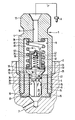
- the figure shows a longitudinal section through a pressure valve 1, which is screwed into the housing 2 of a fuel injection pump, not shown, which is constructed, for example, according to DE-OS 23 53 737.
- the pressure valve 1 has a connecting piece 4, which has an external thread 5 at one end and is screwed with this into a threaded bore 6 in the housing 2.
- a delivery line 7 coaxially opens into the threaded bore from the pump work chamber of the fuel injection pump (not shown). This has a connection via the pressure valve 1 to a further delivery line 7 ', to the end of which an injection valve 8 is connected.
- the connecting piece 4 is constructed essentially cylindrical and has an axial cylindrical recess 9 which is open towards the screw-in side. Coaxial to the cylindrical recess 9 there is a connection bore 11 which opens into a connection nipple 12 of the connection piece and connects the recess 9 to the delivery line 7 'or the injection valve 8.
- a tubular valve seat body 14 is inserted into the axial recess 9, which has a collar 15 at its end, at the end of the pump work space, by means of which it is held by a shoulder 17 on the bottom of the threaded bore 6 through the end 16 of the connection piece on the pump work space.
- the tubular valve seat body 14 has a valve seat 19 on which a conical sealing surface 20 of a valve closing member 21 of the pressure valve comes to rest.
- the valve closing member has, in a known manner, wing-shaped guide surfaces 23 which are guided in the axial bore 24 of the valve seat body 14 and between which fuel can pass to the valve seat.
- the valve closing member is designed as a cylinder 25, which is significantly reduced in diameter compared to the diameter of the bore 24.
- the valve closing member has a collar 26 which is fitted into the bore 24 of the valve seat body.
- the collar 26 On its outer circumference, the collar 26 has a bevel 27 which produces a throttle connection between the part of the cylinder 25 on the guide surface side and the part on the sealing surface side.
- the valve closing member 21 also has coaxially a relief channel 28 which on the one hand has an outlet 30 on the part of the cylinder 25 on the leading surface and on the other hand opens centrally on the end face of a pin 31. This sits on an end face 32 of the valve closing member, which adjoins the sealing surface 20 and limits the valve closing member to the interior of the recess 9.
- the pin 31 serves to center a cup-shaped part 34, the cylindrical wall of which merges into an outer collar 35 which is placed flush on the end face 32.
- the pin 31 protrudes into the cylindrical interior 36 of the cup-shaped part 34.
- a closing spring 37 is placed on the outer collar 35, which on the other hand is supported on the end face 38 of the recess 9 and holds the cup-shaped part 34 in a positive connection with the valve closing member 21 and endeavors to keep this with its sealing surface 20 on the valve seat 19.
- the cup-shaped part 34 can also be connected to the valve closing member in some other way. B. also serve a weld.
- a check valve 46 is provided with a closing spring 40, which is supported on the one hand on the end face of the pin 31 and on the other hand acts on a valve plate 41 which serves to guide a spherical valve closing member 42.
- This has a seat in a conical recess 43 at the bottom of the pot-shaped part, this recess merging into a throttle 44 which opens into the spring chamber 45 of the recess 9 receiving the pressure-locking spring 37.
- valve closing member 21 is raised under the influence of the pressure of the fuel supplied via the delivery line 7, as shown in the figure. If only a small amount of fuel is pumped per unit of time, this can flow past the bevel 27 through the throttle connection without the collar 26 having to be completely removed from the bore 24.
- the valve is only raised slightly, as shown in the drawing, and yet a pressure builds up in the delivery line 7 ′, which is above the opening pressure of the injection valve 8 and causes an injection. At the end of the delivery stroke, the pressure collapses on the pump side, so that the valve closing member 21 is brought into the closed position under the action of the valve closing spring 37.
- the collar 26, which is also referred to as a suck-back collar, draws fuel back from the area upstream of the valve seat 19 in accordance with its previous stroke until the valve closing member comes into the closed position.
- the amount of suckback is reduced by the amount of fuel that flows as a compensating flow through the throttle connection 27 during this movement. In this way, the fuel is relieved in the delivery line between the valve closing member and the injection valve 8 in a known manner.
- pressure waves run in a known manner through the delivery line 7 due to the dynamic conditions, which are reflected on the valve closing member 21 and run back and forth between the injection valve and the valve closing member.
- These pressure waves can reach pressure values which are higher than the opening pressure of the injection valve, so that there is no aftertreatment splash of fuel can come, as already described.
- the average pressure in the delivery line is then still greater than the closing pressure of the injection valve due to the dynamic pressure conditions.
- the peak pressures of the pressure waves are higher, the higher the total residual pressure in the delivery line 7 'after the valve closing member 21 has closed.
- a check valve 46 establishes a connection from the spring chamber 45 or the delivery line 7 ′ to the delivery line 7 on the pump work chamber side beyond the valve closing member 21 when the opening pressure of this check valve is exceeded.
- a certain amount of fuel can flow off via the throttle 44, which causes a reduction of the pressure wave that has arrived.
- the wave then reflected towards the injection valve has pressure values that are not above the opening pressure of the injection valve.
- the throttle influence of the throttle connection 27 increases in such a way that the suckback collar 26 emerges from the bore 24 and the fuel delivered can flow unthrottled past the suckback collar into the spring chamber 45.
- the full valve closing member stroke is effective for sucking back fuel quantities.
- the relief association essentially takes over the relief of the injection line to prevent post-injection alone.
- the amount of relief is then essentially a relief volume of valve stroke x free annular surface of the end face of the relief collar 26.
- the throttle connection 27 also flows during the rapid stroke movement of the Valve closing member no significant compensation amounts past, so that the delivery line is relieved to a maximum.
- the throttle connection 27 on the return suction collar can also be produced with the aid of an increased play between collar 26 and bore 24 or through bores in the collar itself.
- the closing member 21 would first have to carry out the full stroke, which corresponds to the relief stroke, until the connection from the delivery line 7 to the delivery line 7 'is made.
- the low delivery rate would result in a delayed injection point.
- the delivery line 7 ' would be relieved in particular in the same way as the closing member, as is the case with partial load or full load or with high delivery rates. This relief corresponds to a swallowing volume which is high for a low delivery rate during idling operation and which has to be filled up until a pressure is reached in the delivery line 7 'which corresponds to the opening pressure of the injection valve.
- a spray delay would also occur here and a correspondingly long pre-delivery stroke would be required for the pump piston.
- This long pre-conveying stroke which, owing to the low conveying rate achieved by the quiet running device, is even greater than in normal operation without a quiet running device, necessitates that in the injection pump a relatively large useful stroke, the stroke which is effective for fuel delivery to the fuel injector, must be made available.
- this useful stroke for idling is lost to the clean stroke in the rest of the load range. This complicates the use of a silent running device to a considerable extent or requires a complex pump design with a high useful stroke.
- the delivery line 7 ' is relieved only slightly at low delivery rates, particularly in the area of quiet operation.
- the check valve 46 is provided, by means of which the pressure peaks are reduced in this operating range by fuel through the throttle 44 when the check valve is open, the interior 36 and the relief channel 35 can flow back to the pump work space via the outlet 30.
- a desired residual pressure can be maintained in the various operating areas of the internal combustion engine in the delivery line 7 'without the opening pressure of the injection nozzles being exceeded after they are closed .
- the opening pressure of the check valve is advantageously chosen so that it is approximately as large as the injection valve closing pressure. This means that a very high stand pressure or residual pressure in the delivery line are observed with the lowest swallowing volume.
- long spray times are obtained in idle-quiet operation, without these being as large as with a pressure valve which has no check valve. In this case, very high residual pressures would remain in the delivery lines 7 'because of the throttle connection 27 and thus very long spraying times would occur, some of which would be extended by post-spraying.
Landscapes
- Engineering & Computer Science (AREA)
- Chemical & Material Sciences (AREA)
- Combustion & Propulsion (AREA)
- Mechanical Engineering (AREA)
- General Engineering & Computer Science (AREA)
- Fuel-Injection Apparatus (AREA)
- Check Valves (AREA)
Applications Claiming Priority (2)
| Application Number | Priority Date | Filing Date | Title |
|---|---|---|---|
| DE19843417210 DE3417210A1 (de) | 1984-05-10 | 1984-05-10 | Druckventil |
| DE3417210 | 1984-05-10 |
Publications (2)
| Publication Number | Publication Date |
|---|---|
| EP0163078A1 true EP0163078A1 (fr) | 1985-12-04 |
| EP0163078B1 EP0163078B1 (fr) | 1988-06-29 |
Family
ID=6235383
Family Applications (1)
| Application Number | Title | Priority Date | Filing Date |
|---|---|---|---|
| EP85104323A Expired EP0163078B1 (fr) | 1984-05-10 | 1985-04-10 | Soupape de refoulement |
Country Status (7)
| Country | Link |
|---|---|
| US (1) | US4648369A (fr) |
| EP (1) | EP0163078B1 (fr) |
| JP (1) | JPS60247049A (fr) |
| KR (1) | KR930010661B1 (fr) |
| BR (1) | BR8502199A (fr) |
| DE (2) | DE3417210A1 (fr) |
| SU (1) | SU1489583A3 (fr) |
Cited By (4)
| Publication number | Priority date | Publication date | Assignee | Title |
|---|---|---|---|---|
| FR2607554A1 (fr) * | 1986-11-27 | 1988-06-03 | Daimler Benz Ag | Pompe d'injection de carburant a commande par rampe oblique pour moteur a combustion interne, notamment pour moteur a injection directe pour vehicules utilitaires |
| EP0325211A1 (fr) * | 1988-01-18 | 1989-07-26 | Diesel Kiki Co., Ltd. | Soupape d'équilibrage de pression |
| EP2011998A3 (fr) * | 2007-07-06 | 2009-03-04 | Denso Corporation | Pompe à carburant pour moteur à combustion interne |
| EP2495431A1 (fr) * | 2011-03-04 | 2012-09-05 | OMT Officine Meccaniche Torino S.p.A. | Pompe hydraulique en particulier pompe à carburant |
Families Citing this family (53)
| Publication number | Priority date | Publication date | Assignee | Title |
|---|---|---|---|---|
| JPS61138875A (ja) * | 1984-12-12 | 1986-06-26 | Nissan Motor Co Ltd | 燃料噴射装置の燃料吐出弁 |
| JPS62169256U (fr) * | 1986-04-17 | 1987-10-27 | ||
| DE3704743A1 (de) * | 1987-02-14 | 1988-08-25 | Schaeffler Waelzlager Kg | Steuereinrichtung fuer ein ventil |
| JPS63151972U (fr) * | 1987-03-27 | 1988-10-05 | ||
| EP0325858B1 (fr) * | 1988-01-16 | 1992-09-16 | Lucas Industries Public Limited Company | Soupape de commande de pression |
| DE3843819A1 (de) * | 1988-09-09 | 1990-03-22 | Bosch Gmbh Robert | Druckventil |
| JP2969635B2 (ja) * | 1988-12-16 | 1999-11-02 | 株式会社デンソー | 燃料噴射ポンプ |
| DE59002856D1 (de) * | 1989-11-13 | 1993-10-28 | Bosch Gmbh Robert | Druckventil. |
| JPH04121456A (ja) * | 1990-09-12 | 1992-04-22 | Nissan Motor Co Ltd | 直噴式ディーゼルエンジン |
| GB9302566D0 (en) * | 1993-02-10 | 1993-03-24 | Lucas Ind Plc | Valve |
| US5477829A (en) * | 1994-08-08 | 1995-12-26 | Ford Motor Company | Automotive returnless fuel system pressure valve |
| US5582202A (en) * | 1994-12-21 | 1996-12-10 | Bridge Products, Inc. | Air conditioner system charge/relief valve |
| US5546981A (en) * | 1995-01-12 | 1996-08-20 | Gilbarco, Inc. | Check valve |
| DE19535368C2 (de) * | 1995-09-25 | 1998-04-30 | Bosch Gmbh Robert | Kraftstoffeinspritzeinrichtung für Brennkraftmaschinen |
| DE19645643A1 (de) * | 1996-11-06 | 1998-05-07 | Braun Ag | Überdruckventil für eine Munddusche |
| DE19706591A1 (de) * | 1997-02-20 | 1998-08-27 | Bosch Gmbh Robert | Druckventil |
| JP2001263187A (ja) * | 2000-03-17 | 2001-09-26 | Denso Corp | エンジン用燃料供給装置のチェックバルブ |
| JP4140175B2 (ja) * | 2000-07-21 | 2008-08-27 | 株式会社デンソー | 内燃機関用蓄圧式燃料噴射装置 |
| KR100384299B1 (ko) * | 2000-11-27 | 2003-05-16 | 현대자동차주식회사 | 연료맥동음 저감장치 |
| DE10146113A1 (de) * | 2001-09-19 | 2003-04-03 | Sms Demag Ag | Spritzbalken für eine hydraulische Entzunderungsanlage |
| US6988488B2 (en) * | 2003-04-15 | 2006-01-24 | Visteon Global Technologies, Inc. | Fuel pressure relief valve |
| US7028708B1 (en) | 2003-05-09 | 2006-04-18 | Hydro-Gear Limited Partnership | Combined check valve and pressure relief valve |
| US7007708B2 (en) * | 2003-10-17 | 2006-03-07 | Delphi Techonologies, Inc. | Flow control valve |
| US7296594B1 (en) | 2005-03-22 | 2007-11-20 | Hydro-Gear Limited Partnership | Combination check valve and neutral valve assembly for use in a hydraulic component |
| CN100473821C (zh) * | 2005-03-30 | 2009-04-01 | 株式会社电装 | 具有柱塞的燃油泵及使用这种燃油泵的燃油供应系统 |
| JP4453028B2 (ja) * | 2005-03-30 | 2010-04-21 | 株式会社デンソー | 高圧燃料ポンプ |
| US7451780B1 (en) | 2005-05-16 | 2008-11-18 | Hydro-Gear Limited Partnership | Multifunction valve for use in a hydraulic component |
| US8091583B2 (en) * | 2005-06-16 | 2012-01-10 | Raval A.C.S. Ltd. | Double check valve for a fuel system |
| US7628140B2 (en) * | 2007-09-27 | 2009-12-08 | Caterpillar Inc. | High-pressure pump or injector plug or guide with decoupled sealing land |
| JP4595996B2 (ja) * | 2007-11-16 | 2010-12-08 | トヨタ自動車株式会社 | 内燃機関の高圧燃料供給装置 |
| US20100257916A1 (en) * | 2008-03-27 | 2010-10-14 | Ip Innovative Products, Llc | Accuracy enhancing valve assembly and related method of use |
| US8561638B2 (en) * | 2008-12-02 | 2013-10-22 | Piolax Inc. | Check valve |
| JP4775488B2 (ja) * | 2009-11-30 | 2011-09-21 | トヨタ自動車株式会社 | 内燃機関の高圧燃料供給装置 |
| US8132558B2 (en) * | 2009-12-01 | 2012-03-13 | Stanadyne Corporation | Common rail fuel pump with combined discharge and overpressure relief valves |
| JP5051279B2 (ja) * | 2009-12-21 | 2012-10-17 | 株式会社デンソー | 定残圧弁 |
| US8622046B2 (en) | 2010-06-25 | 2014-01-07 | Caterpillar Inc. | Fuel system having accumulators and flow limiters |
| JP2012172749A (ja) * | 2011-02-21 | 2012-09-10 | Fuji Koki Corp | バルブ装置 |
| JP5501272B2 (ja) * | 2011-03-08 | 2014-05-21 | 日立オートモティブシステムズ株式会社 | 高圧燃料供給ポンプ |
| DE112012003664T5 (de) * | 2011-09-01 | 2014-08-14 | Piolax Inc. | Rückschlagventil |
| DE112012004564T5 (de) * | 2011-11-01 | 2014-08-21 | Cummins Inc. | Kraftstoff-Einspritzungsvorrichtung mit Einspritzregelventilpatrone |
| JP5920636B2 (ja) * | 2013-09-13 | 2016-05-18 | 株式会社デンソー | 高圧ポンプ |
| JP1546565S (fr) * | 2015-08-19 | 2016-03-28 | ||
| US20180223817A1 (en) * | 2017-02-03 | 2018-08-09 | Peopleflo Manufacturing, Inc. | Reciprocating Pump Having a Combination Check Valve and Relief Valve |
| DE102018114200A1 (de) | 2017-06-15 | 2018-12-20 | Borgwarner Inc. | Spanner mit Rückschlagventil mit steuerbarer Steifigkeit |
| JP6747482B2 (ja) * | 2017-09-29 | 2020-08-26 | 株式会社デンソー | 高圧ポンプ |
| WO2019065992A1 (fr) * | 2017-09-29 | 2019-04-04 | 株式会社デンソー | Pompe haute pression |
| JP7495348B2 (ja) | 2018-02-26 | 2024-06-04 | ボーグワーナー インコーポレーテッド | 内部リザーバ技術一次ボアを有する可変力テンショナ |
| CN109708347A (zh) * | 2018-10-12 | 2019-05-03 | 青岛海尔股份有限公司 | 制冰机的供水装置及具有其的制冰机和冰箱 |
| JP2020101279A (ja) | 2018-12-21 | 2020-07-02 | ボーグワーナー インコーポレーテッド | 内部チェックバルブを含むピストンが備えられたテンショナ |
| HUP1900114A1 (hu) * | 2019-04-05 | 2020-10-28 | Kerox Ipari Es Kereskedelmi Kft | Vezérelt dugattyús szelep |
| US11408525B2 (en) * | 2020-04-10 | 2022-08-09 | II Peter Stephen Heberling | Pressure relief valve for inflatable structures and boats |
| US12181046B2 (en) | 2021-04-13 | 2024-12-31 | Borgwarner Inc. | Variable stiffness function through a check valve in a hydraulic |
| EP4377592A1 (fr) * | 2021-07-29 | 2024-06-05 | Beaconmedaes LLC | Clapet antiretour à débit élevé destiné à des applications de gaz médical |
Citations (6)
| Publication number | Priority date | Publication date | Assignee | Title |
|---|---|---|---|---|
| GB566957A (en) * | 1942-04-01 | 1945-01-22 | Bendix Aviat Corp | Improvement in fuel injection apparatus |
| FR1050441A (fr) * | 1950-11-17 | 1954-01-07 | British Internal Combust Eng | Perfectionnements aux dispositifs d'injection de combustible liquide |
| US2706490A (en) * | 1950-01-18 | 1955-04-19 | Nordberg Manufacturing Co | Variable retraction valve |
| CH394710A (de) * | 1962-08-09 | 1965-06-30 | Schweizerische Lokomotiv | Brennstoffeinspritzpumpe für Brennkraftmaschinen |
| US3479999A (en) * | 1967-11-02 | 1969-11-25 | Ulrikh Ulrikhovich Keller | Injection pump valve |
| GB2095344A (en) * | 1981-03-21 | 1982-09-29 | Bosch Gmbh Robert | Fuel injection pump for internal combustion engines |
Family Cites Families (8)
| Publication number | Priority date | Publication date | Assignee | Title |
|---|---|---|---|---|
| US3477458A (en) * | 1965-01-07 | 1969-11-11 | Int Harvester Co | Fuel delivery valve assembly and method |
| US3309024A (en) * | 1965-01-07 | 1967-03-14 | Int Harvester Co | Fuel delivery valve and injection apparatus employing same |
| US3933132A (en) * | 1971-10-20 | 1976-01-20 | Isuzu Motors Limited | Another liquid-mixing injection system for internal-combustion engine |
| FR2296104A2 (fr) * | 1973-12-13 | 1976-07-23 | Sigma Diesel | Perfectionnements apportes aux dispositifs d'injection pour moteur a combustion interne |
| US3896845A (en) * | 1974-06-13 | 1975-07-29 | Gen Motors Corp | Accumulator charging and relief valve |
| JPS5675957A (en) * | 1979-11-21 | 1981-06-23 | Diesel Kiki Co Ltd | Draft device of delivery valve for fuel injection pump |
| JPS56115849A (en) * | 1980-02-15 | 1981-09-11 | Nippon Denso Co Ltd | Fuel injection pump for internal combustion engine |
| DE3138211A1 (de) * | 1981-09-25 | 1983-04-07 | Robert Bosch Gmbh, 7000 Stuttgart | Kraftstoff-einspritzpumpe fuer brennkraftmaschinen |
-
1984
- 1984-05-10 DE DE19843417210 patent/DE3417210A1/de not_active Withdrawn
-
1985
- 1985-04-08 US US06/720,771 patent/US4648369A/en not_active Expired - Fee Related
- 1985-04-10 DE DE8585104323T patent/DE3563553D1/de not_active Expired
- 1985-04-10 EP EP85104323A patent/EP0163078B1/fr not_active Expired
- 1985-05-07 SU SU853886806A patent/SU1489583A3/ru active
- 1985-05-09 BR BR8502199A patent/BR8502199A/pt not_active IP Right Cessation
- 1985-05-09 KR KR1019850003156A patent/KR930010661B1/ko not_active Expired - Lifetime
- 1985-05-10 JP JP60098190A patent/JPS60247049A/ja active Pending
Patent Citations (6)
| Publication number | Priority date | Publication date | Assignee | Title |
|---|---|---|---|---|
| GB566957A (en) * | 1942-04-01 | 1945-01-22 | Bendix Aviat Corp | Improvement in fuel injection apparatus |
| US2706490A (en) * | 1950-01-18 | 1955-04-19 | Nordberg Manufacturing Co | Variable retraction valve |
| FR1050441A (fr) * | 1950-11-17 | 1954-01-07 | British Internal Combust Eng | Perfectionnements aux dispositifs d'injection de combustible liquide |
| CH394710A (de) * | 1962-08-09 | 1965-06-30 | Schweizerische Lokomotiv | Brennstoffeinspritzpumpe für Brennkraftmaschinen |
| US3479999A (en) * | 1967-11-02 | 1969-11-25 | Ulrikh Ulrikhovich Keller | Injection pump valve |
| GB2095344A (en) * | 1981-03-21 | 1982-09-29 | Bosch Gmbh Robert | Fuel injection pump for internal combustion engines |
Cited By (4)
| Publication number | Priority date | Publication date | Assignee | Title |
|---|---|---|---|---|
| FR2607554A1 (fr) * | 1986-11-27 | 1988-06-03 | Daimler Benz Ag | Pompe d'injection de carburant a commande par rampe oblique pour moteur a combustion interne, notamment pour moteur a injection directe pour vehicules utilitaires |
| EP0325211A1 (fr) * | 1988-01-18 | 1989-07-26 | Diesel Kiki Co., Ltd. | Soupape d'équilibrage de pression |
| EP2011998A3 (fr) * | 2007-07-06 | 2009-03-04 | Denso Corporation | Pompe à carburant pour moteur à combustion interne |
| EP2495431A1 (fr) * | 2011-03-04 | 2012-09-05 | OMT Officine Meccaniche Torino S.p.A. | Pompe hydraulique en particulier pompe à carburant |
Also Published As
| Publication number | Publication date |
|---|---|
| BR8502199A (pt) | 1986-01-07 |
| SU1489583A3 (ru) | 1989-06-23 |
| KR850008704A (ko) | 1985-12-21 |
| DE3563553D1 (en) | 1988-08-04 |
| EP0163078B1 (fr) | 1988-06-29 |
| DE3417210A1 (de) | 1985-11-14 |
| US4648369A (en) | 1987-03-10 |
| JPS60247049A (ja) | 1985-12-06 |
| KR930010661B1 (ko) | 1993-11-05 |
Similar Documents
| Publication | Publication Date | Title |
|---|---|---|
| EP0163078B1 (fr) | Soupape de refoulement | |
| EP0116168B1 (fr) | Pompe d'injection de combustible | |
| DE3910793C2 (de) | Brennstoffeinspritzvorrichtung | |
| EP0142008B1 (fr) | Soupape de refoulement pour des pompes d'injection de combustible | |
| DE2704688C2 (fr) | ||
| DE2803049A1 (de) | Pumpe-duese fuer brennkraftmaschinen | |
| DE3521427C2 (fr) | ||
| DE3629751C2 (de) | Voreinspritzvorrichtung für Brennkraftmaschinen | |
| EP0688950B1 (fr) | Système d'injection de carburant | |
| EP0204982B1 (fr) | Dispositif d'injection de combustible pour moteurs à combustion interne | |
| DE19844891A1 (de) | Kraftstoffeinspritzventil für Brennkraftmaschinen | |
| DE3715614A1 (de) | Kraftstoffeinspritzpumpe | |
| DE10117600C1 (de) | Hochdruck-Kraftstoffpumpe für ein Kraftstoffsystem einer direkteinspritzenden Brennkraftmaschine, Kraftstoffsystem sowie Brennkraftmaschine | |
| DE69625992T2 (de) | Einspritzventil | |
| EP1045975B1 (fr) | Unite servant a commander l'etablissement de la pression dans une unite de pompage | |
| DE4106813A1 (de) | Kraftstoffeinspritzpumpe fuer brennkraftmaschinen | |
| DE2509068C2 (fr) | ||
| DE19812170A1 (de) | Kraftstoffeinspritzanlage für eine mehrzylindrige Brennkraftmaschine | |
| DE19942291C2 (de) | Kraftstoffeinspritzventil für eine Brennkraftmaschine | |
| DE3436042A1 (de) | Kraftstoffeinspritzpumpe fuer selbstzuendende brennkraftmaschinen | |
| DE10023960A1 (de) | Kraftstoffeinspritzvorrichtung für eine Brennkraftmaschine | |
| EP0610584B1 (fr) | Dispositif d'injection de combustible à pré-injection et injection principale de combustibles différents par un injecteur mono-aiguille | |
| AT397129B (de) | Kraftstoffeinspritzdüse | |
| DE2658833C2 (fr) | ||
| DE916605C (de) | Verfahren einer in Vor- und Haupteinspritzung unterteilten Kraftstoffeinspritzung mittels Einspritzpumpe |
Legal Events
| Date | Code | Title | Description |
|---|---|---|---|
| PUAI | Public reference made under article 153(3) epc to a published international application that has entered the european phase |
Free format text: ORIGINAL CODE: 0009012 |
|
| 17P | Request for examination filed |
Effective date: 19850410 |
|
| AK | Designated contracting states |
Designated state(s): DE FR GB IT |
|
| 17Q | First examination report despatched |
Effective date: 19860911 |
|
| D17Q | First examination report despatched (deleted) | ||
| GRAA | (expected) grant |
Free format text: ORIGINAL CODE: 0009210 |
|
| AK | Designated contracting states |
Kind code of ref document: B1 Designated state(s): DE FR GB IT |
|
| GBT | Gb: translation of ep patent filed (gb section 77(6)(a)/1977) | ||
| REF | Corresponds to: |
Ref document number: 3563553 Country of ref document: DE Date of ref document: 19880804 |
|
| ET | Fr: translation filed | ||
| ITF | It: translation for a ep patent filed | ||
| PLBE | No opposition filed within time limit |
Free format text: ORIGINAL CODE: 0009261 |
|
| STAA | Information on the status of an ep patent application or granted ep patent |
Free format text: STATUS: NO OPPOSITION FILED WITHIN TIME LIMIT |
|
| 26N | No opposition filed | ||
| ITTA | It: last paid annual fee | ||
| PGFP | Annual fee paid to national office [announced via postgrant information from national office to epo] |
Ref country code: GB Payment date: 19930405 Year of fee payment: 9 |
|
| PGFP | Annual fee paid to national office [announced via postgrant information from national office to epo] |
Ref country code: FR Payment date: 19930429 Year of fee payment: 9 |
|
| PGFP | Annual fee paid to national office [announced via postgrant information from national office to epo] |
Ref country code: DE Payment date: 19930624 Year of fee payment: 9 |
|
| PG25 | Lapsed in a contracting state [announced via postgrant information from national office to epo] |
Ref country code: GB Effective date: 19940410 |
|
| GBPC | Gb: european patent ceased through non-payment of renewal fee |
Effective date: 19940410 |
|
| PG25 | Lapsed in a contracting state [announced via postgrant information from national office to epo] |
Ref country code: FR Effective date: 19941229 |
|
| PG25 | Lapsed in a contracting state [announced via postgrant information from national office to epo] |
Ref country code: DE Effective date: 19950103 |
|
| REG | Reference to a national code |
Ref country code: FR Ref legal event code: ST |