EP0163219A1 - Tragplatte mit Spannvorrichtung - Google Patents
Tragplatte mit Spannvorrichtung Download PDFInfo
- Publication number
- EP0163219A1 EP0163219A1 EP85106123A EP85106123A EP0163219A1 EP 0163219 A1 EP0163219 A1 EP 0163219A1 EP 85106123 A EP85106123 A EP 85106123A EP 85106123 A EP85106123 A EP 85106123A EP 0163219 A1 EP0163219 A1 EP 0163219A1
- Authority
- EP
- European Patent Office
- Prior art keywords
- support plate
- clamping
- lever
- plate according
- drive
- Prior art date
- Legal status (The legal status is an assumption and is not a legal conclusion. Google has not performed a legal analysis and makes no representation as to the accuracy of the status listed.)
- Granted
Links
- 210000000629 knee joint Anatomy 0.000 claims description 5
- 230000008878 coupling Effects 0.000 description 3
- 238000010168 coupling process Methods 0.000 description 3
- 238000005859 coupling reaction Methods 0.000 description 3
- 238000004519 manufacturing process Methods 0.000 description 3
- 230000001174 ascending effect Effects 0.000 description 1
- 150000001875 compounds Chemical class 0.000 description 1
- 230000000994 depressogenic effect Effects 0.000 description 1
- 210000003127 knee Anatomy 0.000 description 1
- 238000003825 pressing Methods 0.000 description 1
- 239000007787 solid Substances 0.000 description 1
Images


Classifications
-
- B—PERFORMING OPERATIONS; TRANSPORTING
- B25—HAND TOOLS; PORTABLE POWER-DRIVEN TOOLS; MANIPULATORS
- B25B—TOOLS OR BENCH DEVICES NOT OTHERWISE PROVIDED FOR, FOR FASTENING, CONNECTING, DISENGAGING OR HOLDING
- B25B5/00—Clamps
- B25B5/06—Arrangements for positively actuating jaws
- B25B5/12—Arrangements for positively actuating jaws using toggle links
-
- B—PERFORMING OPERATIONS; TRANSPORTING
- B25—HAND TOOLS; PORTABLE POWER-DRIVEN TOOLS; MANIPULATORS
- B25B—TOOLS OR BENCH DEVICES NOT OTHERWISE PROVIDED FOR, FOR FASTENING, CONNECTING, DISENGAGING OR HOLDING
- B25B5/00—Clamps
- B25B5/06—Arrangements for positively actuating jaws
- B25B5/12—Arrangements for positively actuating jaws using toggle links
- B25B5/122—Arrangements for positively actuating jaws using toggle links with fluid drive
Definitions
- the invention relates to a support plate with a clamping device according to the preamble of the main claim.
- Clamping devices of the type mentioned are known from US Pat. No. 2,436,941.
- the further relevant state of the art in this regard is represented, for example, by the following publications: DE-GM 78 06 055, GB-PS 778 865 and US-PS 3 480 271.
- Such clamping devices are attached to or placed on workpiece support plates or the like, for example attached, the clamping lever in the closed position pressing the workpiece in question (for example. body or body part) against the support plate and holding it clamped. This means that the support plate around the contour of the workpiece in question is occupied with clamping devices.
- the invention is therefore based on the object, provided that the smallest possible passage openings in the support surface to create a support plate with a clamping device, in which the clamping lever is pivoted out of the support surface for surfacing, in the clamping position to the workpiece and with as little effort and space as possible
- the dead center lock can be energized and vice versa can be relaxed or unlocked, swiveled and sunk.
- Fig.- 13 there is Spannvorrich - below the supporting plate 13 of a four-bar linkage formed from the wings 2, 3, the clamping levers 1 and from a solid compound (support plate 13 ') to which the stationary pivots 9 , 10 of the rockers 2, 3 are arranged.
- the drive member 6 is formed from a toggle lever 6 ', the stationary joint 15 of which is also seated on the carrier plate 13'.
- the motion drive introduced at the joint 11 leads to a movement of the parts 6 ', 2, 3, 1 in the sense of the arrows shown, for example the points A, B of the hook 1 "traversing the dash-dotted, very narrow curves (FIG. 2) 2, 3 do not need to be explained individually and only serve to illustrate an intermediate position and the tensioned position in which the toggle lever 6 'is in a somewhat depressed over-center position.
- the ascending movement of the hook 1 " Tensioning lever 1 thus takes place in a very narrow area, so that the through opening 14 in the support plate 13, under which the support plate 13 'is fastened in a suitable manner, can be kept correspondingly small.
- the drive is effected by a pneumatic cylinder 17 articulated on the hinge 16 of the support plate 13 '.
- an over-center stop 7 is also attached to the support plate 13', which ensures that the hook end 8 'with further pressure the piston rod does not easily lift off the object to be tensioned and the articulated members of the knee lever cannot be pushed upwards.
- the possibility of reaching an over-dead center position also with this device is essential insofar as the clamping position must be maintained irrespective of whether the pressure in the cylinder is present or not.
- a correspondingly guided coupling rod can be arranged perpendicular to the plane of representation when a whole series of clamping devices on the support plate 13 are arranged, which only have a small overall width according to FIG. 4, which coupling rod has a fork-like design at the end is detected and the areas on the joints 11 are formed as rollers against which the buckle push rod.
- a firm connection of the piston rod to the knee joint 11, as shown, is namely - this also applies to a single arrangement of the device with its own drive - not absolutely necessary, since the toggle lever 6 'with the piston rod of the cylinder '17 retracted easily by other suitable means can be pushed out of the over-dead center position shown in FIGS. 3, 4.
- a further actuating cylinder could of course also be provided for this purpose, coupled to a wedge to be adjusted, which acts on the knee joint 11.
- Such drive elements that can only be brought into operative connection are of particular interest for the transport vehicles mentioned in the automotive industry, since these vehicles must be able to be uncoupled individually from production lines if necessary and the clamped workpieces located thereon.
- the tensioning device of the support plate 13 can be moved extremely short-stroke (the illustrations have a scale of about 1: 1), it is also absolutely unproblematic to provide for a manual drive which, for example, presses the knee joint 11 upwards with a suitably dimensioned curve .
- the short-stroke nature of the tensioning device which can be accommodated in space-constrained spaces in a way that takes up little space, is due to the fact that the tensioning lever 1 is erected from a somewhat lying position with a narrow arc movement and at the end of this uprighting movement again slightly downwards is pulled and brought into the tensioned position.
- the actuating cylinder 17 does not have to be assigned vertically to the tensioning device, as shown, but this can also be arranged horizontally at the head of the piston rod with the interposition of a suitable motion converter (curve guide piece or the like).
- support plate is of course to be understood so that it can also be a contact plate to which the object to be clamped is attached laterally and then, as described, clamped.
Landscapes
- Engineering & Computer Science (AREA)
- Mechanical Engineering (AREA)
- Automobile Manufacture Line, Endless Track Vehicle, Trailer (AREA)
- Jigs For Machine Tools (AREA)
- Clamps And Clips (AREA)
- Pallets (AREA)
Abstract
Description
- Die Erfindung betrifft eine Tragplatte mit Spannvorrichtung gemäß Oberbegriff des Hauptanspruches.
- Spannvorrichtungen der genannten Art sind nach der US-PS 2 436 941 bekannt. Der weitere diesbezüglich einschlägige Stand der Technik wird bspw. durch folgende Druckschriften repräsentiert: DE-GM 78 06 055, GB-PS 778 865 und US-PS 3 480 271. Solche Spannvorrichtungen werden bspw. an Werkstücksauflageplatten od. dgl. an-oder aufgesetzt befestigt, wobei der Spannhebel in Schließstellung das betreffende Werkstück (bspw. Karosserie oder Karosserieteil) gegen die Auflageplatte drückt und festgespannt hält. Dies bedeutet, daß die Auflageplatte rings um die Kontur des betreffenden Werkstückes mit Spannvorrichtungen besetzt ist. Durch moderne Fertigungsmethoden, insbesondere in der Autoindustrie, ist die Forderung entstanden, die im Zuge einer Fertigungsstraße hintereinander angeordneten, aber auch beliebig im Bedarfsfall herausnehmbaren Transportwagen mit Spannvorrichtungen auszustatten, die mit möglichst geringer Raumbeanspruchung am Werkstück ansetzbar sind und die bei Nichtbedarf völlig in bzw. unter der eigentlichen Aufstellfläche des Transportwagens zum Verschwinden gebracht werden können. Abgesehen davon ist eine solche Forderung bspw. auch für Ladeflächen von Interesse, die bspw. genormte Container aufnehmen sollen, da man bei Erfüllung dieser Forderung den betreffenden Gegenstand, von Spannvorrichtungen unbehindert, in bezug auf die Ladefläche auf- und abschieben kann.
- Der Erfindung liegt also die Aufgabe zugrunde, unter Voraussetzung des Vorhandenseins möglichst kleiner Durchgriffsöffnungen in der Auflagefläche eine Tragplatte mit Spannvorrichtung zu schaffen, bei der mit möglichst geringem Aufwand und möglichst geringer Raumbeanspruchung der Spannhebel aus der Auflagefläche zum Auftauchen, in Spannstellung zum Werkstück geschwenkt und mit Übertotpunktverriegelung unter Spannung gebracht und umgekehrt wieder entspannt bzw. entriegelt, abgeschwenkt und versenkt werden kann.
- Diese Aufgabe ist durch eine Tragplatte mit Spannvorrichtung der eingangs genannten Art nach der Erfindung durch die im Kennzeichen des Hauptanspruches angeführten Merkmale gelöst. Vorteilhafte, bevorzugte und praktische Ausführungs- und Weiterbildungsformen ergeben sich nach den Unteransprüchen.
- Durch die erfindungsgemäße Lösung sind die gestellten Forderungen denkbar einfach erfüllt, und es ergeben sich folgende Vorteile:
- Die Spannkräfte vergleichbarer "normaler" Spannvorrichtungen sind ohne weiteres erreichbar. Zum Vollzug des speziellen Bewegungsablaufes des Spannhebels
- Die erfindungsgemäße Tragplatte wird nachfolgend an Hand der zeichnerischen Darstellung eines Ausführungsbeispieles näher erläutert.
- Es zeigt schematisch
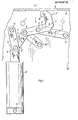
- Fig. l einen Tragplattenabschnitt mit Spannvorrichtung in versenkter Stellung;
- Fig. 2 den Tragplattenabschnitt gemäß Fig. 1 mit Spannvorrichtung in einer Zwi-chenstellung beim Ausfahren;
- Fig. 3 den Tragplattenabschnitt mit Spannvorrichtung in Spannstellung und
- Fig. 4 eine Seitenansicht des Tragplattenabschnittes mit Spannvorrichtung.
- Wie aus Fig.- 1 - 3 erkennbar, besteht die Spannvorrich- tung der Tragplatte 13 aus einem Gelenkviereck, gebildet aus den Schwingen 2, 3, dem Spannhebel 1 und aus einer festen Verbindung (Trägerplatte 13'), an der die stationären Gelenke 9, 10 der Schwingen 2, 3 angeordnet sind. Das Antriebsglied 6 ist aus einem Kniehebel 6' gebildet, dessen stationäres Gelenk 15 ebenfalls an der Trägerplatte 13' sitzt. Der Spannhebel 1 überragt mit seinem als Haken l" ausgebildeten Spannteil l' das Gelenk 4 der Schwinge 3.
- Der am Gelenk 11 eingeleitete Bewegungsantrieb führt zu einer Bewegung der Teile 6', 2, 3, 1 im Sinne der eingezeichneten Pfeile, wobei bspw. die Punkte A, B des Hakens l" die strichpunktierten, sehr schmalen Kurven durchfahren (Fig. 2). Die STellungen gemäß Fig. 2, 3 bedürfen keiner Einzelerläuterung und dienen nur zur Verdeutlichung einer Zwischenstellung und der Spannstellung, bei der der Kniehebel 6' sich in etwas durchgedrückter Übertotpunktstellung befindet. Die Auftauchbewegung des als Haken 1" ausgebildeten Spannhebels 1 vollzieht sich also in einem sehr schma- len Bereich, so daß die Durchgriffsöffnung 14 in der Auflageplatte 13, unter der senkrecht die Trägerplat- te 13' in geeigneter Weise befestigt ist, entsprechend klein gehalten werden kann.
- Beim dargestellten Ausführungsbeispiel erfolgt der Antrieb durch einen am Gelenk 16 der Trägerplatte 13' angelenkten Pneumatikzylinder 17. Im SUellweg des Kniehebels 61 ist ein Übertotpunktanschlag 7 ebenfalls an der Trägerplatte 13' befestigt, der dafür sorgt, daß sich das Hakenende 8' bei weiterem Druck der Kolbenstange nicht wieder vom zu spannenden Gegenstand leicht abhebt und die Gelenkglieder des Kniehebels nicht nach oben durchgedrückt werden können. Die Möglichkeit der Erreichung einer Übertotpunktstellung auch bei dieser Vorrichtung ist insofern wesentlich, als die Spannstellung unabhängig vom An- oder Nichtanliegen des Druckes im Zylinder erhalten bleiben muß.
- Wie ohne weiteres vorstellbar und wie erwähnt, kann bei Anordnung einer ganzen Reihe von Spannvorrichtungen an der Tragplatte 13,die gemäß Fig. 4 nur eine geringe Baubreite haben, senkrecht zur Darstellungsebene eine entsprechend geführte Koppelungsstange angeordnet werden, die mit einer am Ende gabelartig ausgebildeten Kolbenstange erfaßt wird und wobei die Bereiche an den Gelenken 11 als Rollen ausgebildet sind, gegen die die Koppelungsstange drückt. Eine feste Verbindung der Kolbenstange mit dem Kniegelenk 11, wie dargestellt, ist nämlich - dies gilt auch für eine Einzelanordnung der Vorrichtung mit eigenem Antrieb - nicht zwingend erforderlich, da der Kniehebel 6' bei zurückgefahrener Kolbenstange des Zylinders '17 ohne weiteres mit anderen geeigneten Mitteln aus der in Fig. 3, 4 gezeigten Übertotpunktstellung herausgedrückt werden kann. Dafür könnte natürlich auch ein weiterer Stellzylinder vorgesehen werden, gekoppelt mit einem zu verstellenden Keil, der auf das Kniegelenk 11 wirkt. Derartige nur in Wirkverbindung bringbare Antriebselemente sind insbesondere für die erwähnten Transportwagen in der Autoindustrie von Interesse, da diese Wagen einzeln aus Fertigungsstraßen im Bedarfsfall und den darauf befindlichen festgespannten Werkstücken auskoppelbar sein müssen.
- Da die Spannvorrichtung der Tragplatte 13 äußerst kurzhubig zu bewegen ist (die Darstellungen haben den Maßstab von etwa 1:1), ist es auch absolut problemlos, für einen Handantrieb zu sorgen, der bspw. mit einer geeignet bemessenen Kurve das Kniegelenk 11 nach oben drückt. Die Kurzhubigkeit der Spannvorrichtung, die dadurch auch wenig raumbeanspruchend in beengten Räumen untergebracht werden kann, kommt dadurch zustande, daß der Spannhebel 1 aus einer gewissermaßen liegenden Stellung mit einer engen Bogenbewegung aufgerichtet und am Ende dieser Aufrichtbewegung wieder geringfügig nach unten gezogen und in Spannstellung gebracht wird. Der Betätigungszylinder 17 muß dabei keineswegs der Spannvorrichtung, wie dargestellt, senkrecht zugeordnet werden, sondern dieser kann unter Zwischenschaltung eines geeigneten Bewegungsumsetzers (Kurvenführungsstück od. dgl.) am Kopf der Kolbenstange auch ohne weiteres horizontal angeordnet werden.
- Die Bezeichnung "Tragplatte" ist natürlich so zu verstehen, daß es sich auch um eine Anlegeplatte handeln kann, an die der festzustpannende Gegenstand seitlich angesetzt und dann, wie beschrieben, festgespannt wird.
Claims (9)
daß das Spannteil (1') des Spannhebels (1) in Form eines Hakens (1") ausgebildet ist und daß die Gelenke (4, 5; 9, 10) des Gelenkvierecks derart angeordnet und die Schwingen (2, 3) derart bemessen sind, daß der Spannhebel (1) in Spannstellung die Durchgriffsöffnung (14) durchgreifend (Fig. 2) mit seiner Längsachse (8) quer zu deren Verlauf bei Rückzugsstellung (Fig. 1) des Spannhebels (1) unter der Tragplatte (13) steht.
Priority Applications (1)
| Application Number | Priority Date | Filing Date | Title |
|---|---|---|---|
| AT85106123T ATE36663T1 (de) | 1984-05-28 | 1985-05-18 | Tragplatte mit spannvorrichtung. |
Applications Claiming Priority (2)
| Application Number | Priority Date | Filing Date | Title |
|---|---|---|---|
| DE3419878A DE3419878C1 (de) | 1984-05-28 | 1984-05-28 | Tragplatte insbesondere Transportwagen- od. Palettentragplatte mit Spannvorrichtung |
| DE3419878 | 1984-05-28 |
Publications (2)
| Publication Number | Publication Date |
|---|---|
| EP0163219A1 true EP0163219A1 (de) | 1985-12-04 |
| EP0163219B1 EP0163219B1 (de) | 1988-08-24 |
Family
ID=6237053
Family Applications (1)
| Application Number | Title | Priority Date | Filing Date |
|---|---|---|---|
| EP85106123A Expired EP0163219B1 (de) | 1984-05-28 | 1985-05-18 | Tragplatte mit Spannvorrichtung |
Country Status (3)
| Country | Link |
|---|---|
| EP (1) | EP0163219B1 (de) |
| AT (1) | ATE36663T1 (de) |
| DE (1) | DE3419878C1 (de) |
Cited By (15)
| Publication number | Priority date | Publication date | Assignee | Title |
|---|---|---|---|---|
| EP0747172A1 (de) * | 1995-06-06 | 1996-12-11 | Btm Corporation | Kraftverstärker |
| FR2757437A1 (fr) * | 1996-12-24 | 1998-06-26 | Bruyn Gerard De | Outil pilote de centrage et serrage |
| US5938259A (en) * | 1997-01-10 | 1999-08-17 | Btm Corporation | Pad for universal gripper |
| EP1498223A1 (de) * | 2003-07-16 | 2005-01-19 | UNIVER S.p.A. | Kompakte Spannvorrichtung mit seitlichem Klemmelement |
| EP1386697A3 (de) * | 2002-08-02 | 2005-04-13 | UNIVER S.p.A. | Spannvorrichtung für Werkstücke |
| CN102922451A (zh) * | 2012-11-15 | 2013-02-13 | 昆山迈致治具科技有限公司 | 快速夹装置 |
| CN105458976A (zh) * | 2015-12-31 | 2016-04-06 | 天津贝斯特斯科技有限公司 | 一种液压定位装置 |
| CN106736746A (zh) * | 2016-12-21 | 2017-05-31 | 泉州市联控自动化科技有限公司 | 一种浮动压紧机构 |
| CN108994128A (zh) * | 2018-08-01 | 2018-12-14 | 浙江金瑞五金索具有限公司 | 一种弹簧钩扳弯机 |
| CN110948424A (zh) * | 2019-12-19 | 2020-04-03 | 惠州市精鸿精密科技有限公司 | 一种散热片的加工治具 |
| CN112937903A (zh) * | 2021-03-22 | 2021-06-11 | 贵州航天特种车有限责任公司 | 一种用于无人机弹射的轻量化锁紧装置 |
| CN113263338A (zh) * | 2021-06-09 | 2021-08-17 | 浙江科力车辆控制系统有限公司 | 铰链式装夹加工中心工装 |
| US11103269B2 (en) | 2006-01-31 | 2021-08-31 | Cilag Gmbh International | Motor-driven surgical cutting and fastening instrument with tactile position feedback |
| EP4159374A1 (de) * | 2021-10-03 | 2023-04-05 | Delaware Capital Formation, Inc. | Pneumatische verriegelungsklemme |
| CN118373077A (zh) * | 2024-04-30 | 2024-07-23 | 中铁十二局集团第七工程有限公司 | 一种圆钢存放装置 |
Families Citing this family (18)
| Publication number | Priority date | Publication date | Assignee | Title |
|---|---|---|---|---|
| DE3936396C1 (en) * | 1989-11-02 | 1991-04-25 | Josef Gerhard 4030 Ratingen De Tuenkers | Toggle tightening device - has housing containing toggle with piston and cylinder, and right angled two armed lever pivoted at other end |
| DE8913386U1 (de) * | 1989-11-13 | 1991-03-14 | De-Sta-Co Metallerzeugnisse Gmbh, 6000 Frankfurt | Spannvorrichtung |
| DE3938208C1 (de) * | 1989-11-17 | 1990-11-22 | Josef Gerhard 4030 Ratingen De Tuenkers | |
| DE4429425C1 (de) * | 1994-08-19 | 1995-10-19 | Opel Adam Ag | Spannvorrichtung |
| DE29718643U1 (de) * | 1997-10-21 | 1997-12-11 | Tünkers Maschinenbau GmbH, 40880 Ratingen | Druckmittelbetätigbare kombinierte Zentrier- und Spannvorrichtung, insbesondere zur Verwendung im Karosseriebau der Kfz-Industrie |
| DE69805497T2 (de) * | 1998-02-18 | 2003-01-16 | Delaware Capital Formation, Inc. | Geschlossene pneumatische Spannvorrichtung |
| DE102004040606B3 (de) * | 2004-08-21 | 2006-01-12 | Tünkers Maschinenbau Gmbh | Als Gripper ausgebildete Kniehebelspannvorrichtung, insbesondere zur Verwendung im Karosseriebau der Kfz-Industrie |
| DE102009058985B3 (de) * | 2009-12-18 | 2011-06-01 | Tünkers Maschinenbau Gmbh | Unterbodenspanner zum Zentrieren und Spannen von Werkstücken, insbesondere zur Verwendung im Karosseriebau der Kfz-Industrie |
| CN102626910B (zh) * | 2012-04-26 | 2014-06-11 | 常州星宇车灯股份有限公司 | 快速夹紧组件 |
| CN103753447B (zh) * | 2013-12-27 | 2022-10-21 | 广州奥迪通用照明有限公司 | 一种新型夹具 |
| DE102014100573B3 (de) * | 2014-01-20 | 2015-07-02 | Teamtechnik Maschinen Und Anlagen Gmbh | Toleranzausgleichende Spannvorrichtung umfassend zwei Kniehebel-Einheiten und weiterem Spann-Element |
| CN104384960A (zh) * | 2014-10-30 | 2015-03-04 | 陈昊书 | 一种用于固定夹紧块状零件的装置 |
| CN104385181A (zh) * | 2014-10-30 | 2015-03-04 | 陈昊书 | 一种气动夹紧装置 |
| CN109128939A (zh) * | 2018-10-29 | 2019-01-04 | 唐师正 | 一种自动柔性夹具及加工方法 |
| CN109158922A (zh) * | 2018-11-22 | 2019-01-08 | 李伟 | 一种机械加工用快速夹紧装置 |
| CN111906562A (zh) * | 2019-05-27 | 2020-11-10 | 中车大同电力机车有限公司 | 车钩夹持装置 |
| CN110722524A (zh) * | 2019-10-21 | 2020-01-24 | 深圳市八零联合装备有限公司 | 一种气缸旋转输出装置 |
| DE102020003577B3 (de) * | 2020-06-16 | 2021-06-10 | Olaf und André Tünkers GbR (vertretungsberechtigter Gesellschafter: Dipl.-Ing. Olaf Tünkers, 40883 Ratingen) | Unterbodenspanner mit Kniehebelgelenk und Kulissenführung, zur Verwendung im Karosseriebau der Kfz-lndustrie |
Citations (4)
| Publication number | Priority date | Publication date | Assignee | Title |
|---|---|---|---|---|
| US1274451A (en) * | 1917-05-18 | 1918-08-06 | Firestone Steel Products Co | Clamping mechanism for welders. |
| US3165309A (en) * | 1962-09-13 | 1965-01-12 | Tri Ordinate Corp | Clamping mechanisms |
| US3480271A (en) * | 1967-10-18 | 1969-11-25 | Gen Motors Corp | Toggle clamp |
| DD135455A1 (de) * | 1978-04-17 | 1979-05-09 | Joachim Schmidt | Spannvorrichtung zum schweissen von blechschrankgehaeusen |
Family Cites Families (3)
| Publication number | Priority date | Publication date | Assignee | Title |
|---|---|---|---|---|
| US2436941A (en) * | 1945-03-28 | 1948-03-02 | Jack J Sendoykas | Toggle clamp |
| GB778865A (en) * | 1954-12-08 | 1957-07-10 | Speed Tools Ltd | Improvements in or relating to clamps |
| DE7806055U1 (de) * | 1978-03-01 | 1978-06-15 | De-Sta-Co Metallerzeugnisse Gmbh, 6000 Frankfurt | Kniehebelgelenkspanner |
-
1984
- 1984-05-28 DE DE3419878A patent/DE3419878C1/de not_active Expired
-
1985
- 1985-05-18 EP EP85106123A patent/EP0163219B1/de not_active Expired
- 1985-05-18 AT AT85106123T patent/ATE36663T1/de not_active IP Right Cessation
Patent Citations (4)
| Publication number | Priority date | Publication date | Assignee | Title |
|---|---|---|---|---|
| US1274451A (en) * | 1917-05-18 | 1918-08-06 | Firestone Steel Products Co | Clamping mechanism for welders. |
| US3165309A (en) * | 1962-09-13 | 1965-01-12 | Tri Ordinate Corp | Clamping mechanisms |
| US3480271A (en) * | 1967-10-18 | 1969-11-25 | Gen Motors Corp | Toggle clamp |
| DD135455A1 (de) * | 1978-04-17 | 1979-05-09 | Joachim Schmidt | Spannvorrichtung zum schweissen von blechschrankgehaeusen |
Cited By (20)
| Publication number | Priority date | Publication date | Assignee | Title |
|---|---|---|---|---|
| EP0747172A1 (de) * | 1995-06-06 | 1996-12-11 | Btm Corporation | Kraftverstärker |
| US6115898A (en) * | 1995-06-06 | 2000-09-12 | Btm Corporation | Force multiplying apparatus for clamping a workpiece and forming a joint therein |
| FR2757437A1 (fr) * | 1996-12-24 | 1998-06-26 | Bruyn Gerard De | Outil pilote de centrage et serrage |
| WO1998028110A1 (fr) * | 1996-12-24 | 1998-07-02 | Menage, Christine | Outil pilote de centrage et serrage |
| US5938259A (en) * | 1997-01-10 | 1999-08-17 | Btm Corporation | Pad for universal gripper |
| EP1386697A3 (de) * | 2002-08-02 | 2005-04-13 | UNIVER S.p.A. | Spannvorrichtung für Werkstücke |
| EP1498223A1 (de) * | 2003-07-16 | 2005-01-19 | UNIVER S.p.A. | Kompakte Spannvorrichtung mit seitlichem Klemmelement |
| US7178797B2 (en) | 2003-07-16 | 2007-02-20 | Univer S.P.A. | Compact clamping device with side clamping member |
| US11103269B2 (en) | 2006-01-31 | 2021-08-31 | Cilag Gmbh International | Motor-driven surgical cutting and fastening instrument with tactile position feedback |
| CN102922451A (zh) * | 2012-11-15 | 2013-02-13 | 昆山迈致治具科技有限公司 | 快速夹装置 |
| CN105458976A (zh) * | 2015-12-31 | 2016-04-06 | 天津贝斯特斯科技有限公司 | 一种液压定位装置 |
| CN106736746A (zh) * | 2016-12-21 | 2017-05-31 | 泉州市联控自动化科技有限公司 | 一种浮动压紧机构 |
| CN108994128A (zh) * | 2018-08-01 | 2018-12-14 | 浙江金瑞五金索具有限公司 | 一种弹簧钩扳弯机 |
| CN110948424A (zh) * | 2019-12-19 | 2020-04-03 | 惠州市精鸿精密科技有限公司 | 一种散热片的加工治具 |
| CN110948424B (zh) * | 2019-12-19 | 2021-09-21 | 惠州市精鸿精密科技有限公司 | 一种散热片的加工治具 |
| CN112937903A (zh) * | 2021-03-22 | 2021-06-11 | 贵州航天特种车有限责任公司 | 一种用于无人机弹射的轻量化锁紧装置 |
| CN113263338A (zh) * | 2021-06-09 | 2021-08-17 | 浙江科力车辆控制系统有限公司 | 铰链式装夹加工中心工装 |
| EP4159374A1 (de) * | 2021-10-03 | 2023-04-05 | Delaware Capital Formation, Inc. | Pneumatische verriegelungsklemme |
| US11759915B2 (en) | 2021-10-03 | 2023-09-19 | Delaware Capital Formation, Inc. | Pneumatic latch clamp |
| CN118373077A (zh) * | 2024-04-30 | 2024-07-23 | 中铁十二局集团第七工程有限公司 | 一种圆钢存放装置 |
Also Published As
| Publication number | Publication date |
|---|---|
| DE3419878C1 (de) | 1985-12-19 |
| ATE36663T1 (de) | 1988-09-15 |
| EP0163219B1 (de) | 1988-08-24 |
Similar Documents
| Publication | Publication Date | Title |
|---|---|---|
| EP0163219B1 (de) | Tragplatte mit Spannvorrichtung | |
| DE4211736C2 (de) | Handhabungsvorrichtung | |
| DE3638028A1 (de) | Transferverfahren und -vorrichtung zur verwendung bei der kraftwagenmontage | |
| EP0785167B1 (de) | Seitenschiebereinrichtung für Flurförderzeuge | |
| DE19629487A1 (de) | Handhabungsgerät für den Transport von Gegenständen | |
| DE202004012593U1 (de) | Vorrichtung zur Festlegung und/oder Positionierung von Gegenständen in einem Transportbehälter | |
| DE3881748T2 (de) | Bügelpresse für Kleider. | |
| DE3439292C2 (de) | ||
| EP0203949A1 (de) | Verfahren und vorrichtung zum andocken eines eine auflageebene bildenden trägerelementes an eine ortsfeste auflageebene. | |
| DE2234670C3 (de) | Vorrichtung zum Abbiegen der Enden von Offsetdruckplatten | |
| DE69702512T2 (de) | Vorrichtung zum ziehen und drucken von einer last in eine gewisse ebene | |
| DE2900347A1 (de) | Reifenwechselvorrichtung | |
| EP4339062B1 (de) | Verfahren zum zentrieren bzw. auslenken eines kupplungskopfs eines schienenfahrzeugs, sowie eine abstützvorrichtung zur durchführung des verfahrens | |
| DD229325A5 (de) | Betaetigungsvorrichtung zur verwendung in einer giessereianlage | |
| DE1605012C3 (de) | Fahrzeug, insbesondere Eisenbahnwagen mit aufklappbarem Dach | |
| DE19617700C2 (de) | Schieberverschluss | |
| DE10017315C2 (de) | Vorrichtung zur bewegbaren Lagerung eines oberen Formwerkzeugs | |
| DE8416388U1 (de) | Tragplatte, insbesondere Transportwagen- o. Palettentragplatte, mit Spannvorrichtung für auf der Platte festspannbare Gegenstände | |
| DE3304512C2 (de) | ||
| DE8913386U1 (de) | Spannvorrichtung | |
| EP0426612A1 (de) | Arretiervorrichtung | |
| EP0796777A1 (de) | Stellvorrichtung für eine Eisenbahnweiche | |
| EP1607366B1 (de) | Hubfahrzeug mit einer Scherenhubeinrichtung | |
| DE102020208430B4 (de) | Schmiedemaschinen-Belade- und -Entladevorrichtung | |
| DE2630375C2 (de) | Türanordnung, insbesondere für Behälter, Behälterwagen o.dgl. |
Legal Events
| Date | Code | Title | Description |
|---|---|---|---|
| PUAI | Public reference made under article 153(3) epc to a published international application that has entered the european phase |
Free format text: ORIGINAL CODE: 0009012 |
|
| AK | Designated contracting states |
Designated state(s): AT BE CH FR GB IT LI LU NL SE |
|
| 17P | Request for examination filed |
Effective date: 19851107 |
|
| 17Q | First examination report despatched |
Effective date: 19861028 |
|
| D17Q | First examination report despatched (deleted) | ||
| GRAA | (expected) grant |
Free format text: ORIGINAL CODE: 0009210 |
|
| AK | Designated contracting states |
Kind code of ref document: B1 Designated state(s): AT BE CH FR GB IT LI LU NL SE |
|
| REF | Corresponds to: |
Ref document number: 36663 Country of ref document: AT Date of ref document: 19880915 Kind code of ref document: T |
|
| ET | Fr: translation filed | ||
| ITF | It: translation for a ep patent filed | ||
| GBT | Gb: translation of ep patent filed (gb section 77(6)(a)/1977) | ||
| PG25 | Lapsed in a contracting state [announced via postgrant information from national office to epo] |
Ref country code: LU Free format text: LAPSE BECAUSE OF NON-PAYMENT OF DUE FEES Effective date: 19890531 Ref country code: LI Effective date: 19890531 Ref country code: CH Effective date: 19890531 |
|
| PLBE | No opposition filed within time limit |
Free format text: ORIGINAL CODE: 0009261 |
|
| STAA | Information on the status of an ep patent application or granted ep patent |
Free format text: STATUS: NO OPPOSITION FILED WITHIN TIME LIMIT |
|
| 26N | No opposition filed | ||
| REG | Reference to a national code |
Ref country code: CH Ref legal event code: PL |
|
| ITTA | It: last paid annual fee | ||
| EAL | Se: european patent in force in sweden |
Ref document number: 85106123.4 |
|
| PGFP | Annual fee paid to national office [announced via postgrant information from national office to epo] |
Ref country code: SE Payment date: 19970513 Year of fee payment: 13 Ref country code: GB Payment date: 19970513 Year of fee payment: 13 |
|
| PGFP | Annual fee paid to national office [announced via postgrant information from national office to epo] |
Ref country code: FR Payment date: 19970529 Year of fee payment: 13 |
|
| PGFP | Annual fee paid to national office [announced via postgrant information from national office to epo] |
Ref country code: NL Payment date: 19970530 Year of fee payment: 13 |
|
| PGFP | Annual fee paid to national office [announced via postgrant information from national office to epo] |
Ref country code: AT Payment date: 19970531 Year of fee payment: 13 |
|
| PGFP | Annual fee paid to national office [announced via postgrant information from national office to epo] |
Ref country code: BE Payment date: 19970612 Year of fee payment: 13 |
|
| PG25 | Lapsed in a contracting state [announced via postgrant information from national office to epo] |
Ref country code: GB Free format text: LAPSE BECAUSE OF NON-PAYMENT OF DUE FEES Effective date: 19980518 Ref country code: AT Free format text: LAPSE BECAUSE OF NON-PAYMENT OF DUE FEES Effective date: 19980518 |
|
| PG25 | Lapsed in a contracting state [announced via postgrant information from national office to epo] |
Ref country code: SE Free format text: LAPSE BECAUSE OF NON-PAYMENT OF DUE FEES Effective date: 19980519 |
|
| PG25 | Lapsed in a contracting state [announced via postgrant information from national office to epo] |
Ref country code: FR Free format text: LAPSE BECAUSE OF NON-PAYMENT OF DUE FEES Effective date: 19980531 Ref country code: BE Free format text: LAPSE BECAUSE OF NON-PAYMENT OF DUE FEES Effective date: 19980531 |
|
| BERE | Be: lapsed |
Owner name: DE-STA-CO METALLERZEUGNISSE G.M.B.H. Effective date: 19980531 |
|
| PG25 | Lapsed in a contracting state [announced via postgrant information from national office to epo] |
Ref country code: NL Free format text: LAPSE BECAUSE OF NON-PAYMENT OF DUE FEES Effective date: 19981201 |
|
| GBPC | Gb: european patent ceased through non-payment of renewal fee |
Effective date: 19980518 |
|
| EUG | Se: european patent has lapsed |
Ref document number: 85106123.4 |
|
| NLV4 | Nl: lapsed or anulled due to non-payment of the annual fee |
Effective date: 19981201 |
|
| REG | Reference to a national code |
Ref country code: FR Ref legal event code: ST |