EP0163259B1 - Dispositif de soudage automatique - Google Patents
Dispositif de soudage automatique Download PDFInfo
- Publication number
- EP0163259B1 EP0163259B1 EP19850106338 EP85106338A EP0163259B1 EP 0163259 B1 EP0163259 B1 EP 0163259B1 EP 19850106338 EP19850106338 EP 19850106338 EP 85106338 A EP85106338 A EP 85106338A EP 0163259 B1 EP0163259 B1 EP 0163259B1
- Authority
- EP
- European Patent Office
- Prior art keywords
- heating
- soldering apparatus
- heating members
- soldering
- members
- Prior art date
- Legal status (The legal status is an assumption and is not a legal conclusion. Google has not performed a legal analysis and makes no representation as to the accuracy of the status listed.)
- Expired
Links
Images

Classifications
-
- B—PERFORMING OPERATIONS; TRANSPORTING
- B23—MACHINE TOOLS; METAL-WORKING NOT OTHERWISE PROVIDED FOR
- B23K—SOLDERING OR UNSOLDERING; WELDING; CLADDING OR PLATING BY SOLDERING OR WELDING; CUTTING BY APPLYING HEAT LOCALLY, e.g. FLAME CUTTING; WORKING BY LASER BEAM
- B23K1/00—Soldering, e.g. brazing, or unsoldering
- B23K1/005—Soldering by means of radiant energy
- B23K1/0053—Soldering by means of radiant energy soldering by means of infrared [IR]
Definitions
- the invention relates to an automatic soldering system, for. B. for soldering frames, with a transport device and a heating device, which consists of a number of radiators arranged at a distance from each other in the conveying direction.
- radiators In known soldering systems of the type mentioned, either convection heaters, cast radiator plates, infrared elements or the like are provided as radiators, the temperature of which is basically controllable or regulatable.
- the invention is therefore based on the object of designing a soldering system of the type mentioned in such a way that not only can a predetermined temperature profile be exactly maintained, but also the possibility must also be created that an interruption of the heat radiation occurs as quickly as possible.
- the invention provides that radiant heaters are provided as radiators, that the radiators each have at least one heating element and that the radiators with their radiation surface can be pivoted from a working position about a bearing axis into a rest position, in which heat radiation to the transport device not possible.
- each radiator can therefore be moved from a working position to an ineffective position, which is also selected so that any heat emission in the possible danger area is prevented.
- the radiators are provided with reflector housings and can be pivoted as a unit from the working position into the inactive position.
- heat-insulating or heat-absorbing transverse walls are arranged between adjacent radiators in such a way that the radiating surfaces of the radiators are directed at them in the rest position.
- each radiator 1 comprises a trough-shaped reflector housing 2, which is mounted in lateral bearing rails 4 so that it can pivot about a bearing shaft 3.
- One or more quartz or infrared heating elements 5 are arranged in the reflector housing 2.
- a glass ceramic plate is also provided as the radiation surface 6 and also as a cover for the open side of the reflector housing 2, to which a temperature sensor 7 is also attached.
- the wall of the reflector housing 2 lying at the top in the rest position according to FIG. 2 carries a heat-insulating layer 8 and is also provided with a projecting wall part 9.
- the reflector housing 2 also has a flange 10 which projects downward in the working position according to FIG. 1.
- a fastening point 11 for one end of a Bowden cable 12 is provided on this flange 10.
- the sheath of the Bowden cable 12 is supported on the one hand at a fastening point 13 on the one bearing rail 4 and on the other hand on one leg of a holding bracket 14.
- This bracket 14 carries a pneumatic cylinder 15 serving as an actuator, with the piston stand 16 of which the other end of the Bowden cable 12 is connected.
- a compression spring 17 is arranged between the fastening points 12 and 13 of the Bowden cable 12.
- a heat-absorbing wall 18 is also arranged as an insulating body.
- the wall 18 is preferably made of ceramic and additionally carries a reflection layer 19. Such a wall 18 is arranged next to each radiator 1, and in the rest position the radiator 1 is supported on the wall 18 with its projecting wall part 9. In this position, the radiator is also held by gravity, since the bearing shaft 3 is arranged off-center.
- a connection box 20 is also assigned to each radiator 1.
- the supply lines are expediently guided through the hollow bearing shaft 3 into the reflector housing 2.
- a conveyor belt 32 is mounted in the side walls 31 of the soldering system and moves in the direction of the arrow 33.
- solder frames 34 are spaced apart and carry component plates 35 to be processed.
- the heating device is attached between side walls 36 and consists of a larger number of radiators 1.
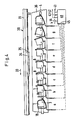
- FIG. 4 eight such radiators 1 are shown one after the other and designated as individual stations with the letters a) to h).
- a soldering frame 34 the relative position of which is electronically scanned in a manner known per se by means not shown, is located according to FIG. 4 just above the radiators 1 of stations c), d) and e) and has station f) in the direction of transport. leave.
- a central control device 40 is provided to control the workflow described below. This is connected via a first line 41 to the drive device of the conveyor belt 32 and via a second line 42 to the position control sensor mentioned above.
- the control device 40 is connected to each of the temperature sensors 7 of the heating elements 1 via a line group 43.
- a line group 44 connects the control device 40 to the heating elements 5 of each of the heating elements 1.
- a line group 45 connects the control device 40 to each of the actuating devices for pivoting the radiators 1.
- the power supply to the heating elements 5 is regulated by the control device 40 in such a way that each of the heating elements 1 can emit the same or possibly different amounts of heat which can be set by preselection and which can also be sensed by means of the temperature sensor 7.
- the position control of the radiators 1 takes place via the line 42 as a function of the respective position of the soldering frame 34.
- the soldering frame 34 has also already left the stations f) to h), so that they can pivot into their rest position.
- the pivoting movement has just started in station f), has almost ended in station g) and in station h) the radiator 1 is already in its rest position.
- the heat / temperature control can be carried out in such a way that different amounts of heat are emitted in each of the stations or in groups of stations. It is possible, for example, to set the stations h) and g) reached first in the transport direction to a lower temperature value or a lower heat emission than the subsequent stations and z. B. regulate the last station a) again to a lower radiation output or heat emission.
- An emergency signal can finally be sent to the control device 40 via the line 41 leading to the drive of the conveyor belt 32 in the event that the drive has to be stopped for some reason.
Landscapes
- Engineering & Computer Science (AREA)
- Mechanical Engineering (AREA)
- Tunnel Furnaces (AREA)
- Electric Connection Of Electric Components To Printed Circuits (AREA)
Claims (15)
Applications Claiming Priority (2)
| Application Number | Priority Date | Filing Date | Title |
|---|---|---|---|
| DE3419974 | 1984-05-29 | ||
| DE19843419974 DE3419974A1 (de) | 1984-05-29 | 1984-05-29 | Heizvorrichtung fuer eine transportstrasse |
Publications (2)
| Publication Number | Publication Date |
|---|---|
| EP0163259A1 EP0163259A1 (fr) | 1985-12-04 |
| EP0163259B1 true EP0163259B1 (fr) | 1988-03-16 |
Family
ID=6237099
Family Applications (1)
| Application Number | Title | Priority Date | Filing Date |
|---|---|---|---|
| EP19850106338 Expired EP0163259B1 (fr) | 1984-05-29 | 1985-05-23 | Dispositif de soudage automatique |
Country Status (2)
| Country | Link |
|---|---|
| EP (1) | EP0163259B1 (fr) |
| DE (1) | DE3419974A1 (fr) |
Families Citing this family (2)
| Publication number | Priority date | Publication date | Assignee | Title |
|---|---|---|---|---|
| DE3724005A1 (de) * | 1987-07-21 | 1989-02-02 | Friedrich Dieter | Prozessgesteuerte erwaermungseinrichtung |
| DE4302976A1 (de) * | 1992-07-22 | 1994-01-27 | Bosch Gmbh Robert | Vorrichtung und Verfahren zum Auflöten von Bauelementen auf Platinen |
Family Cites Families (11)
| Publication number | Priority date | Publication date | Assignee | Title |
|---|---|---|---|---|
| US3486004A (en) * | 1968-02-12 | 1969-12-23 | Time Research Lab Inc | High speed bonding apparatus |
| US3717743A (en) * | 1970-12-07 | 1973-02-20 | Argus Eng Co | Method and apparatus for heat-bonding in a local area using combined heating techniques |
| US3744557A (en) * | 1971-07-19 | 1973-07-10 | Argus Eng Co | Apparatus for fusing and sealing platings and the like |
| DD100608A1 (fr) * | 1972-11-21 | 1973-09-20 | ||
| US3864546A (en) * | 1973-04-16 | 1975-02-04 | Casso Solar | System for irradiating a discontinuously moving web |
| US3926360A (en) * | 1974-05-28 | 1975-12-16 | Burroughs Corp | Method of attaching a flexible printed circuit board to a rigid printed circuit board |
| DD127037A1 (fr) * | 1976-05-17 | 1977-08-31 | ||
| DE3007037A1 (de) * | 1980-02-26 | 1981-09-03 | Ego Elektro Blanc & Fischer | Glaskeramik-kochgeraet |
| DE3111809C2 (de) * | 1981-03-25 | 1985-05-15 | Zevatron GmbH Gesellschaft für Fertigungseinrichtungen der Elektronik, 3548 Arolsen | Verfahren und Vorrichtung zum maschinellen Löten von Werkstücken |
| DE8307284U1 (de) * | 1983-03-14 | 1984-01-05 | Kirschner GmbH & Co KG Werkzeughandel Präzisionsschleifen, 7094 Unterschneidheim | Vorrichtung zum Vorbeloten von Hartmetallplatten |
| US4600137A (en) * | 1985-02-21 | 1986-07-15 | Hollis Automation, Inc. | Method and apparatus for mass soldering with subsequent reflow soldering |
-
1984
- 1984-05-29 DE DE19843419974 patent/DE3419974A1/de not_active Withdrawn
-
1985
- 1985-05-23 EP EP19850106338 patent/EP0163259B1/fr not_active Expired
Also Published As
| Publication number | Publication date |
|---|---|
| DE3419974A1 (de) | 1985-12-05 |
| EP0163259A1 (fr) | 1985-12-04 |
Similar Documents
| Publication | Publication Date | Title |
|---|---|---|
| DE69105297T2 (de) | Ofen zum Heizen von Glasscheiben. | |
| DE69509613T2 (de) | Bäckereiofen zum kontinuierlichen Kochen von Back- oder Konditorwaren oder ähnlichen | |
| DE2404086C3 (de) | Verfahren und Vorrichtung zum Kühlen von heißem, körnigem Material | |
| EP0691713B1 (fr) | Module de connexion | |
| EP0200120B1 (fr) | Dispositif d'introduction de pièces en forme de plaques déposées sur une table élévatrice dans une installation de séparation de plaques | |
| EP2773914B1 (fr) | Dispositif et procédé permettant de thermoréguler des objets | |
| EP0163259B1 (fr) | Dispositif de soudage automatique | |
| DE2836252B2 (de) | Mikrowellenerhitzungseinrichtung | |
| EP0864391B1 (fr) | Dispositif de chauffage | |
| DE69716495T2 (de) | Unterstützungseinheit für einen vertikalen Tauchkolben | |
| EP3203814A1 (fr) | Système de ruban lumineux omprenant plusieurs modules de ruban lumineux pouvant être commandés | |
| EP1000864B1 (fr) | Proçédé et dispositif pour rétracter une feuille sur un objet | |
| DE29618646U1 (de) | Vorrichtung zur Entwesung von Gebäuden oder Gebäudeteilen | |
| DE102004034204A1 (de) | Heizplatte, insbesondere für einen Laminator | |
| DE3308099A1 (de) | Verfahren zur drahtlosen uebertragung der stellgroesse in einem geschlossenen regelkreis und vorrichtung zur durchfuehrung des verfahrens | |
| DE1471989B1 (de) | Verfahren und Vorrichtung zur gleichmaessigen Erwaermung von plattenfoermigen Werkstuecken,insbesondere von grossen Glasscheiben | |
| WO2007134346A1 (fr) | Four de traitement thermique avec émetteurs de rayons infrarouges | |
| DE102019214489A1 (de) | Trägeranordnung zur verwendung in einer anlage für selektives pulverschmelzen | |
| WO1994021415A1 (fr) | Installation de brasage de composants montes en surface | |
| DD265610A5 (de) | Verfahren und vorrichtung zum ausbauchen und haerten von glastafeln | |
| DE102009011910A1 (de) | Flächenelement zur thermischen Bearbeitung von Stoffen, Gütern und Objekten | |
| DE2105167C2 (de) | Vorrichtung zur Bedampfung je von einem Rahmen getragener Glastafeln | |
| EP2325116A1 (fr) | Dispositif de chargement d'une unité de traitement dotée de sections | |
| EP0975458A1 (fr) | Dispositif pour le chauffage et l'application de materiaux plastiques | |
| DD211938A5 (de) | Verfahren und vorrichtung zum trocknen keramischer formlinge |
Legal Events
| Date | Code | Title | Description |
|---|---|---|---|
| PUAI | Public reference made under article 153(3) epc to a published international application that has entered the european phase |
Free format text: ORIGINAL CODE: 0009012 |
|
| AK | Designated contracting states |
Designated state(s): BE CH FR IT LI NL SE |
|
| 17P | Request for examination filed |
Effective date: 19860526 |
|
| 17Q | First examination report despatched |
Effective date: 19870604 |
|
| GRAA | (expected) grant |
Free format text: ORIGINAL CODE: 0009210 |
|
| AK | Designated contracting states |
Kind code of ref document: B1 Designated state(s): BE CH FR IT LI NL SE |
|
| ET | Fr: translation filed | ||
| ITF | It: translation for a ep patent filed | ||
| PLBE | No opposition filed within time limit |
Free format text: ORIGINAL CODE: 0009261 |
|
| STAA | Information on the status of an ep patent application or granted ep patent |
Free format text: STATUS: NO OPPOSITION FILED WITHIN TIME LIMIT |
|
| 26N | No opposition filed | ||
| PGFP | Annual fee paid to national office [announced via postgrant information from national office to epo] |
Ref country code: FR Payment date: 19910430 Year of fee payment: 7 |
|
| PGFP | Annual fee paid to national office [announced via postgrant information from national office to epo] |
Ref country code: SE Payment date: 19910506 Year of fee payment: 7 |
|
| PGFP | Annual fee paid to national office [announced via postgrant information from national office to epo] |
Ref country code: CH Payment date: 19910507 Year of fee payment: 7 |
|
| PGFP | Annual fee paid to national office [announced via postgrant information from national office to epo] |
Ref country code: BE Payment date: 19910527 Year of fee payment: 7 |
|
| ITTA | It: last paid annual fee | ||
| PGFP | Annual fee paid to national office [announced via postgrant information from national office to epo] |
Ref country code: NL Payment date: 19910531 Year of fee payment: 7 |
|
| PG25 | Lapsed in a contracting state [announced via postgrant information from national office to epo] |
Ref country code: SE Effective date: 19920524 |
|
| PG25 | Lapsed in a contracting state [announced via postgrant information from national office to epo] |
Ref country code: LI Effective date: 19920531 Ref country code: CH Effective date: 19920531 Ref country code: BE Effective date: 19920531 |
|
| BERE | Be: lapsed |
Owner name: HOHNERLEIN ERNST Effective date: 19920531 |
|
| PG25 | Lapsed in a contracting state [announced via postgrant information from national office to epo] |
Ref country code: NL Effective date: 19921201 |
|
| NLV4 | Nl: lapsed or anulled due to non-payment of the annual fee | ||
| PG25 | Lapsed in a contracting state [announced via postgrant information from national office to epo] |
Ref country code: FR Effective date: 19930129 |
|
| REG | Reference to a national code |
Ref country code: CH Ref legal event code: PL |
|
| REG | Reference to a national code |
Ref country code: FR Ref legal event code: ST |
|
| EUG | Se: european patent has lapsed |
Ref document number: 85106338.8 Effective date: 19921204 |