EP0163276A2 - Prise de contact d'antenne - Google Patents
Prise de contact d'antenne Download PDFInfo
- Publication number
- EP0163276A2 EP0163276A2 EP85106430A EP85106430A EP0163276A2 EP 0163276 A2 EP0163276 A2 EP 0163276A2 EP 85106430 A EP85106430 A EP 85106430A EP 85106430 A EP85106430 A EP 85106430A EP 0163276 A2 EP0163276 A2 EP 0163276A2
- Authority
- EP
- European Patent Office
- Prior art keywords
- coaxial
- inner conductor
- terminals
- antenna socket
- cables
- Prior art date
- Legal status (The legal status is an assumption and is not a legal conclusion. Google has not performed a legal analysis and makes no representation as to the accuracy of the status listed.)
- Granted
Links
- 239000004020 conductor Substances 0.000 claims abstract description 51
- 239000002184 metal Substances 0.000 claims description 3
- 230000001419 dependent effect Effects 0.000 description 1
- 238000011161 development Methods 0.000 description 1
- 230000018109 developmental process Effects 0.000 description 1
- 239000000463 material Substances 0.000 description 1
- 230000003313 weakening effect Effects 0.000 description 1
Images
Classifications
-
- H—ELECTRICITY
- H01—ELECTRIC ELEMENTS
- H01R—ELECTRICALLY-CONDUCTIVE CONNECTIONS; STRUCTURAL ASSOCIATIONS OF A PLURALITY OF MUTUALLY-INSULATED ELECTRICAL CONNECTING ELEMENTS; COUPLING DEVICES; CURRENT COLLECTORS
- H01R24/00—Two-part coupling devices, or either of their cooperating parts, characterised by their overall structure
- H01R24/38—Two-part coupling devices, or either of their cooperating parts, characterised by their overall structure having concentrically or coaxially arranged contacts
- H01R24/40—Two-part coupling devices, or either of their cooperating parts, characterised by their overall structure having concentrically or coaxially arranged contacts specially adapted for high frequency
- H01R24/52—Two-part coupling devices, or either of their cooperating parts, characterised by their overall structure having concentrically or coaxially arranged contacts specially adapted for high frequency mounted in or to a panel or structure
- H01R24/525—Outlets
-
- H—ELECTRICITY
- H01—ELECTRIC ELEMENTS
- H01R—ELECTRICALLY-CONDUCTIVE CONNECTIONS; STRUCTURAL ASSOCIATIONS OF A PLURALITY OF MUTUALLY-INSULATED ELECTRICAL CONNECTING ELEMENTS; COUPLING DEVICES; CURRENT COLLECTORS
- H01R2105/00—Three poles
Definitions
- This invention relates to an antenna socket with one or in particular two connection sockets for coaxial high-frequency plugs with two adjacent terminals for the inner conductor of coaxial high-frequency cables and with two electrically connected clamps for the outer conductor of the coaxial high-frequency cable.
- Antenna sockets are to be used to make coaxial connections both on the antenna side and on the receiver side. On the receiver side, this is done with the help of coaxial plugs and on the antenna side, usually by clamping the stripped inner conductor of the coaxial cable in a screw or spring terminal and by clamping the exposed outer conductor of the coaxial * cable using a clamp.
- antenna sockets which can be used as through-type sockets
- connection options are provided for two coaxial cables, the connecting terminals for the inner conductor and the clamps for the outer conductor of the coaxial cable being electrically connected to one another.
- the arrangement of the connection devices for the two coaxial cables is such that the cables lead into and out of the antenna socket on one and the same side of the latter.
- the object of the invention is to create an antenna socket which can be used as a through-type socket and in which the two coaxial cables can either be on one side or opposite lying sides of the antenna socket can be inserted into this.
- the new antenna socket not only has outer conductor clamps for two coaxial cables inserted next to each other, but two outer conductor double clamps, one of which is arranged in front of and one behind the inner conductor terminals.
- the inner conductor connection sockets are designed such that an inner conductor can be inserted and clamped into them from both ends. This makes it possible to insert and connect two coaxial cables of your choice either from opposite sides - or only from one side into the antenna socket, or to insert and connect two cables side by side into the antenna socket on the two opposite sides.
- the Outer conductor double clamps connected to each other by an electrically conductive cover, which ensures that the connection of the coaxial cable is sufficiently radio frequency tight.
- the shield formed by this cover is preferably supplemented by a separate metallic connection of the lower parts of the outer conductor double clamps.
- the cover is preferably a pivotally mounted sheet metal, which contacts both double clamps in its one end position, and which can be pivoted up for the assembly of the coaxial cables, so that the inner conductor connecting terminals are easily accessible. After assembly is complete, the sheet is swung back so that it lies on the two outer conductor double clamps. In this position, it can be fixed by a spring, by a latching device or by the cover, which is usually placed on the antenna socket.
- the antenna socket according to the invention can also be used to transmit signals received by a satellite reception antenna and transmitted by two coaxial cables, one cable transmitting right-hand circularly polarized signals and the other cable left-hand circularly polarized signals, which are fed separately to the two sockets of the antenna socket are, which is why the adjacent inner conductor terminals assigned to the two sockets are also left electrically separated from one another in this application.
- this application there are again two connection options: Either you just lead the two ⁇ kcmaxial cables coming from the antenna into the antenna socket, one of which is connected to one socket and the other to the second socket, or you use the antenna socket as a through socket by feeding four coaxial cables, two of which come from the antenna and two continue, e.g. B. to another antenna socket; in this case, one connects two cables coming from opposite directions to each of the two connecting sockets.
- the inner conductor connection is preferably symmetrical between the connection sockets for the coaxial plug.
- the provided cover of the outer conductor double clamps ensures the high-frequency tightness of the cable connections continuous
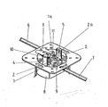
- connection sockets 4 and 5 are provided for connecting two coaxial plugs.
- inner conductor connection terminals 2 which are electrically conductively connected to one another by a common web carrying the threaded bores for the clamping screws 2a.
- Two outer conductor double clamps 1 and 1 a are provided symmetrically on both sides of the inner conductor connecting terminals 2 and are used to contact and intercept a maximum of four coaxial cables on their outer conductors.
- a metal plate 3 is pivotally mounted about an axis 11 running parallel to the double clamps 1 and 1a, which is folded up for the connection of the coaxial cables 6 and 7 and folded down after assembly ⁇ and then both outer conductor double clamps 1 and 1a rests, electrically connects them and covers the inner conductor terminals 2 at a distance.
- two separate inner conductor connecting terminals can be electrically connected to one another by a bridge (which could be fixed by the two clamping screws 2a) or replaced by two inner conductor connecting terminals 2 combined into a block, as shown in the drawing.
Landscapes
- Support Of Aerials (AREA)
- Multi-Conductor Connections (AREA)
- Details Of Aerials (AREA)
- Coupling Device And Connection With Printed Circuit (AREA)
Priority Applications (1)
| Application Number | Priority Date | Filing Date | Title |
|---|---|---|---|
| AT85106430T ATE47940T1 (de) | 1984-05-26 | 1985-05-24 | Antennensteckdose. |
Applications Claiming Priority (2)
| Application Number | Priority Date | Filing Date | Title |
|---|---|---|---|
| DE8416118U DE8416118U1 (de) | 1984-05-26 | 1984-05-26 | Antennensteckdose |
| DE8416118U | 1984-05-26 |
Publications (3)
| Publication Number | Publication Date |
|---|---|
| EP0163276A2 true EP0163276A2 (fr) | 1985-12-04 |
| EP0163276A3 EP0163276A3 (en) | 1987-05-20 |
| EP0163276B1 EP0163276B1 (fr) | 1989-11-08 |
Family
ID=6767292
Family Applications (1)
| Application Number | Title | Priority Date | Filing Date |
|---|---|---|---|
| EP85106430A Expired EP0163276B1 (fr) | 1984-05-26 | 1985-05-24 | Prise de contact d'antenne |
Country Status (3)
| Country | Link |
|---|---|
| EP (1) | EP0163276B1 (fr) |
| AT (1) | ATE47940T1 (fr) |
| DE (2) | DE8416118U1 (fr) |
Cited By (2)
| Publication number | Priority date | Publication date | Assignee | Title |
|---|---|---|---|---|
| US4813888A (en) * | 1986-10-15 | 1989-03-21 | Matsushita Electric Works, Ltd. | High-frequency cable connector |
| EP2843777A1 (fr) | 2013-09-02 | 2015-03-04 | Ceconet AG | Boîte de jonction universelle destinée au prélèvement de signaux multimédia HF avec DIP switch |
Family Cites Families (4)
| Publication number | Priority date | Publication date | Assignee | Title |
|---|---|---|---|---|
| DE1302931C2 (de) * | 1966-04-20 | 1972-05-31 | Siemens Ag | Befestigungsvorrichtung, insbesondere für Antennensteckdosen, mit einer als gewölbte Scheibe ausgebildelen Halteschelle |
| DE2228233A1 (de) * | 1972-06-09 | 1973-12-20 | Siemens Ag | Antennensteckdose |
| DE2538670B2 (de) * | 1975-08-30 | 1978-08-10 | Richard Hirschmann Radiotechnisches Werk, 7300 Esslingen | Klemmenabschirmung für Antennensteckdosen |
| DE2733220C3 (de) * | 1977-07-22 | 1980-11-20 | Siemens Ag, 1000 Berlin Und 8000 Muenchen | Antennensteckdose mit einem topfförmigen Dosenkörper |
-
1984
- 1984-05-26 DE DE8416118U patent/DE8416118U1/de not_active Expired
-
1985
- 1985-05-24 DE DE8585106430T patent/DE3574206D1/de not_active Expired
- 1985-05-24 EP EP85106430A patent/EP0163276B1/fr not_active Expired
- 1985-05-24 AT AT85106430T patent/ATE47940T1/de not_active IP Right Cessation
Cited By (2)
| Publication number | Priority date | Publication date | Assignee | Title |
|---|---|---|---|---|
| US4813888A (en) * | 1986-10-15 | 1989-03-21 | Matsushita Electric Works, Ltd. | High-frequency cable connector |
| EP2843777A1 (fr) | 2013-09-02 | 2015-03-04 | Ceconet AG | Boîte de jonction universelle destinée au prélèvement de signaux multimédia HF avec DIP switch |
Also Published As
| Publication number | Publication date |
|---|---|
| ATE47940T1 (de) | 1989-11-15 |
| EP0163276A3 (en) | 1987-05-20 |
| EP0163276B1 (fr) | 1989-11-08 |
| DE8416118U1 (de) | 1984-08-30 |
| DE3574206D1 (en) | 1989-12-14 |
Similar Documents
| Publication | Publication Date | Title |
|---|---|---|
| DE69120688T2 (de) | Mehrpoliger abgeschirmter verbinder mit gemeinsamer erdung | |
| DE102011078622B4 (de) | Rundsteckverbinder mit abgeschirmtem Anschlusskabel und einsetzbarem Hakenelement sowie Bausatz dazu | |
| EP0247662A1 (fr) | Connexion de traversée pour signaux HF | |
| DE69712850T2 (de) | Vorrichtung zur mechanischen und elektrischen Verbindung von zwei Teilbaugruppen eines Kraftfahrzeugwechselstromgenerators | |
| DE2746376C2 (de) | Koppelvorrichtung zwischen einer Koaxialleitung und einem Hohlleiter | |
| EP0163276B1 (fr) | Prise de contact d'antenne | |
| EP0494427B1 (fr) | Compteur d'électricité | |
| DE19848835A1 (de) | Mehrpolige Steckverbindung | |
| EP0178259A2 (fr) | Guide d'ondes avec une source primaire | |
| DE2339559C2 (de) | Kondensatoranordnung | |
| EP0902507B1 (fr) | Connecteur pour câble coaxial | |
| DE2706447A1 (de) | Steckverbinder fuer eine geschlossene sammelschienenanordnung | |
| DE1918124A1 (de) | Elektrische Anschlussvorrichtung | |
| DE4331143C1 (de) | Anschlußdose zur Bildung einer Anschlußeinrichtung für ein Datennetz | |
| EP0299162A2 (fr) | Connecteur multipolaire incorporé | |
| DE2722619A1 (de) | Antennensteckdose | |
| CH684042A5 (de) | Steckdose. | |
| DE69021875T2 (de) | Bewegliche übertragungsantenne. | |
| DE69115616T2 (de) | Elektrischer Verbinder ausgerüstet mit einem Sicherungshalter | |
| DE69719139T2 (de) | Antennenvorrichtung zum Ausstrahlen und/oder Empfangen von Funksignalen | |
| DE1790274B2 (de) | Elektrischer schalter mit einem hermetisch abgeschlossenen gehaeuse | |
| DE4110897A1 (de) | Vorrichtung zur verbindung einer autoradioantenne | |
| DE3608183C1 (en) | Antenna plug socket | |
| DE69301409T2 (de) | Element eines elektrischen Verbinders | |
| DE2844106A1 (de) | Abgestimmte antenne mit veraenderlicher gegenseitiger magnetischer kopplung |
Legal Events
| Date | Code | Title | Description |
|---|---|---|---|
| PUAI | Public reference made under article 153(3) epc to a published international application that has entered the european phase |
Free format text: ORIGINAL CODE: 0009012 |
|
| AK | Designated contracting states |
Designated state(s): AT BE CH DE FR GB IT LI LU NL SE |
|
| PUAL | Search report despatched |
Free format text: ORIGINAL CODE: 0009013 |
|
| AK | Designated contracting states |
Kind code of ref document: A3 Designated state(s): AT BE CH DE FR GB IT LI LU NL SE |
|
| 17P | Request for examination filed |
Effective date: 19870523 |
|
| 17Q | First examination report despatched |
Effective date: 19881024 |
|
| GRAA | (expected) grant |
Free format text: ORIGINAL CODE: 0009210 |
|
| AK | Designated contracting states |
Kind code of ref document: B1 Designated state(s): AT BE CH DE FR GB IT LI LU NL SE |
|
| ITF | It: translation for a ep patent filed | ||
| REF | Corresponds to: |
Ref document number: 47940 Country of ref document: AT Date of ref document: 19891115 Kind code of ref document: T |
|
| GBT | Gb: translation of ep patent filed (gb section 77(6)(a)/1977) | ||
| REF | Corresponds to: |
Ref document number: 3574206 Country of ref document: DE Date of ref document: 19891214 |
|
| ET | Fr: translation filed | ||
| PLBE | No opposition filed within time limit |
Free format text: ORIGINAL CODE: 0009261 |
|
| STAA | Information on the status of an ep patent application or granted ep patent |
Free format text: STATUS: NO OPPOSITION FILED WITHIN TIME LIMIT |
|
| 26N | No opposition filed | ||
| ITTA | It: last paid annual fee | ||
| EPTA | Lu: last paid annual fee | ||
| EAL | Se: european patent in force in sweden |
Ref document number: 85106430.3 |
|
| PGFP | Annual fee paid to national office [announced via postgrant information from national office to epo] |
Ref country code: BE Payment date: 19970505 Year of fee payment: 13 |
|
| PGFP | Annual fee paid to national office [announced via postgrant information from national office to epo] |
Ref country code: DE Payment date: 19970506 Year of fee payment: 13 |
|
| PGFP | Annual fee paid to national office [announced via postgrant information from national office to epo] |
Ref country code: GB Payment date: 19970515 Year of fee payment: 13 |
|
| PGFP | Annual fee paid to national office [announced via postgrant information from national office to epo] |
Ref country code: SE Payment date: 19970520 Year of fee payment: 13 |
|
| PGFP | Annual fee paid to national office [announced via postgrant information from national office to epo] |
Ref country code: AT Payment date: 19970521 Year of fee payment: 13 |
|
| PGFP | Annual fee paid to national office [announced via postgrant information from national office to epo] |
Ref country code: FR Payment date: 19970526 Year of fee payment: 13 |
|
| PGFP | Annual fee paid to national office [announced via postgrant information from national office to epo] |
Ref country code: CH Payment date: 19970527 Year of fee payment: 13 |
|
| PGFP | Annual fee paid to national office [announced via postgrant information from national office to epo] |
Ref country code: NL Payment date: 19970531 Year of fee payment: 13 |
|
| PGFP | Annual fee paid to national office [announced via postgrant information from national office to epo] |
Ref country code: LU Payment date: 19970908 Year of fee payment: 13 |
|
| PG25 | Lapsed in a contracting state [announced via postgrant information from national office to epo] |
Ref country code: LU Free format text: LAPSE BECAUSE OF NON-PAYMENT OF DUE FEES Effective date: 19980524 Ref country code: GB Free format text: LAPSE BECAUSE OF NON-PAYMENT OF DUE FEES Effective date: 19980524 Ref country code: AT Free format text: LAPSE BECAUSE OF NON-PAYMENT OF DUE FEES Effective date: 19980524 |
|
| PG25 | Lapsed in a contracting state [announced via postgrant information from national office to epo] |
Ref country code: SE Free format text: LAPSE BECAUSE OF NON-PAYMENT OF DUE FEES Effective date: 19980525 |
|
| PG25 | Lapsed in a contracting state [announced via postgrant information from national office to epo] |
Ref country code: LI Free format text: LAPSE BECAUSE OF NON-PAYMENT OF DUE FEES Effective date: 19980531 Ref country code: FR Free format text: LAPSE BECAUSE OF NON-PAYMENT OF DUE FEES Effective date: 19980531 Ref country code: CH Free format text: LAPSE BECAUSE OF NON-PAYMENT OF DUE FEES Effective date: 19980531 Ref country code: BE Free format text: LAPSE BECAUSE OF NON-PAYMENT OF DUE FEES Effective date: 19980531 |
|
| BERE | Be: lapsed |
Owner name: WILHELM SIHN JR. K.G. Effective date: 19980531 |
|
| PG25 | Lapsed in a contracting state [announced via postgrant information from national office to epo] |
Ref country code: NL Free format text: LAPSE BECAUSE OF NON-PAYMENT OF DUE FEES Effective date: 19981201 |
|
| GBPC | Gb: european patent ceased through non-payment of renewal fee |
Effective date: 19980524 |
|
| REG | Reference to a national code |
Ref country code: CH Ref legal event code: PL |
|
| EUG | Se: european patent has lapsed |
Ref document number: 85106430.3 |
|
| NLV4 | Nl: lapsed or anulled due to non-payment of the annual fee |
Effective date: 19981201 |
|
| PG25 | Lapsed in a contracting state [announced via postgrant information from national office to epo] |
Ref country code: DE Free format text: LAPSE BECAUSE OF NON-PAYMENT OF DUE FEES Effective date: 19990302 |
|
| REG | Reference to a national code |
Ref country code: FR Ref legal event code: ST |