EP0163310A2 - Fabrication de plaques profilées autoportantes - Google Patents
Fabrication de plaques profilées autoportantes Download PDFInfo
- Publication number
- EP0163310A2 EP0163310A2 EP85106678A EP85106678A EP0163310A2 EP 0163310 A2 EP0163310 A2 EP 0163310A2 EP 85106678 A EP85106678 A EP 85106678A EP 85106678 A EP85106678 A EP 85106678A EP 0163310 A2 EP0163310 A2 EP 0163310A2
- Authority
- EP
- European Patent Office
- Prior art keywords
- rolls
- profiling
- machine
- venation
- portable
- Prior art date
- Legal status (The legal status is an assumption and is not a legal conclusion. Google has not performed a legal analysis and makes no representation as to the accuracy of the status listed.)
- Withdrawn
Links
Images




Classifications
-
- B—PERFORMING OPERATIONS; TRANSPORTING
- B21—MECHANICAL METAL-WORKING WITHOUT ESSENTIALLY REMOVING MATERIAL; PUNCHING METAL
- B21D—WORKING OR PROCESSING OF SHEET METAL OR METAL TUBES, RODS OR PROFILES WITHOUT ESSENTIALLY REMOVING MATERIAL; PUNCHING METAL
- B21D13/00—Corrugating sheet metal, rods or profiles; Bending sheet metal, rods or profiles into wave form
- B21D13/04—Corrugating sheet metal, rods or profiles; Bending sheet metal, rods or profiles into wave form by rolling
- B21D13/045—Corrugating sheet metal, rods or profiles; Bending sheet metal, rods or profiles into wave form by rolling the corrugations being parallel to the feeding movement
Definitions
- This invention relates to the production of profiled and curved metallic roof tiles and roofs, e.g. for warehouses, industrial buildings and other structures, and provides a process and a device for producing such metallic coverings or roofs right on the building site.
- the device which is the subject of this invention will produce tiles that are profiled and curved in single pieces in the exact and same length as the free empty space of the structure to be covered. Such tiles have their strength calculated to avoid the building of support structures, therefore being self-supporting.
- a machine for producing profiled self-portable tiles comprises means for continuously profiling metal strip to form a tile transportably mounted and pivotable so as to deliver the profiled strip upwards fromthe horizontal.
- the invention provides a process of producing elongated, profiled, self-portable tiles which comprises passing a strip of metal through a transportably mounted train of profiling rolls and hence to the pcsition where the tile is to be installed.
- the tile is produced either from galvanised or pre-painted strip supplied in the form of coils, which are drawn on to the truck- machine by means of a windlass with ratchet (1).
- the coil is mounted horizontally between plates (2) over an axle (3).
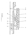
- the profiling begins when the end of the coil is introduced through two plain parallel axles (4) like a calender. Afterwards, it is immediately received by a pair of superposed rolls (5) of different diameters covered with a layer of rubber. The function of these rolls is to draw the strip. The following pairs of rolls, also superposed, successively shape the strip until the desired profile of the tile is reached.
- small auxiliary rolls of small diameter are used. These small rolls may be located at any point of the strip, and over or under it, within the body of the machine. To use them, one just has to verify where in the tile the deformation is taking place.
- novelties that will guide the present specifications include the adjusting and supporting system, corresponding to each pair of rolls, the method of operating them and the balancing of the machine.
- the rolls are made of circular sections (7), of different diameters and are mounted on an axle (8).
- the sections are held together by screws with beam (9) one at each side, screwed over the axle. This system allows lateral displacements of the assembly enabling their alignment and their centering in relation to the guillotine.
- roller bearings that are set in a square bases, the bearings (10). These bearings, in turn, are set in a female type mortise fitted-in the frame of the device. This mortise, the link (11), is positioned vertically in such a way that the rolls are fitted in the upper part, sliding over its bed until they reach the end of a screw (12) that serves as a stop.
- this screw has the characteristics of an internal micrometer.
- the pairs of rolls are moved vertically.
- the movement of each pair of rolls, and which pairs of rolls are to be moved, is always in accordance with the degree of curvature desired. So that we may set these movements, the upper part of the link is closed by a cap through which passes a last screw (14)-.
- This screw also has the characteristics of a micrometer, though to measure in depth.
- the motive power is generated by a stationary motor (18) connected to the machine.
- a reduction gearbox of cylindrical gear wheels with exchange (19) is used to transfer the motive power to the rolls.
- This gearbox receives the power through "V" belts (20) and transmits it to the rolls through a double gear wheel (21), mounted at its exit, which is integrated in the roll operating circuit.
- a hydraulic engine is usually integrated into the existing hydraulic circuit, excluding the reducer, with additional advantages as it is lighter and more compact, and besides it may be connected at any point of the operating circuit.
- Tests made by the applicant for this patent, show that it is possible to cover free empty spaces up to 30 metres, since a curvature of approximately 3.50 metres of deflection can be obtained in the finished tile.
- the device not only profiles the tiles horizontally but also has a low height, long before the tile reaches the desired length it already.touches the ground.
- a balancing system in which the device is divided into two distinct parts, namely the chassis (22) (the upper part that supports the rolls), and the base (23).
- the linkage between these parts is located approximately in the middle of the length of the device and comprises a pair of hinges (24).
- the chassis may be moved by an angular movement in such a way that the end from where the tile emerges remains pointing upwards.
- two extra support arms are used, one fixed (26) and the other telescopic (27).
- Both the guillotine and the control platform (28) are connected to the chassis by extendible arms (29) and hinges (30), allowing their adjustment according to the angle of inclination of the chassis, in order to level the platform and to give the guillotine a perpendicular position in relation to the tile.
- the tile is mounted using trestles (31) fixed on supporting profiles (32) made of angle iron, which lean on the upper'beam (33) of the wall.
- Tie-rods (35) are used in order to avoid the need for over-sized metallic or masonry structures to counter the thrust of the tile (34) that causes horizontal movement of the walls.
- Another novel feature of this invention comprises a mechanical venation (corrugating) device that, connected to the profiling and bending machine and placed between the last group of profiling rolls and the first group of bending rolls, working synchronously with both groups, preferably using their motion transmission system, perform - s a cold venation transverselyto the lateral and longitudinal sections of the adjusted tile, offering it, according to tests made by the applicant, a greater mechanical resistance to the efforts and demands arising from the effects of wind and of the weight of the self-portable covering, installed. It also assists the curving of the self-portable tile to small radii and higher deflections in circular structures with metallic strips.
- the device for venation of self-portable tiles is located between the last group of profiling rolls (A) and the first group of bending rolls (B) and is essentially composed of a structure or supporting frame (36) whose columns (37) integrate an upper horizontal axle (38) on which is located a gear wheel (39) conjugated to the machine transmission chain system (40) and also, in a parallel and posterior plane relative to the gear wheel (39), a gear wheel, part of a pair of intermediate gear wheels (41), interconnected by chain (42), on whose lower horizontal axle (43) of that pair, in a parallel plane and posterior to it there is a main gear wheel or ".planet” (44) conjugated, in the same plane, to a moving gear wheel or upper “satellite” (45) located on a horizontal axle (46) and to a moving gear wheel or lower “satellite” (47) located on a horizontal axle (48) that is conjugated to a moving gear wheel (49) located on a horizontal axle (50) parallel to the axle (48), and within
- the machine and process of the invention can provide a self-portable tile profiled in several lengths and widths, with its own profile, longitudinally curved, and with transverse venation along its edges. They also allow the production of self-portable tiles with a smaller bending radius or curvature than the conventional ones, as from a minimum of six metres, and also allow the use of metallic plates of a minor thickness in the smaller free empty spaces to be covered. They also allow the use of venation both in the plane and curved self-portable tiles, as pre-determined by the utility machine.
- This invention is concerned, inter alia, with a machine to profile self-portable tiles for warehouses, industries and other structures, assembled in a truck chassis, whose purpose is to produce the mentioned metallic coverings or roofs right on the building site.
- This machine offers construction and functioning technical characteristics totally different from those presented by similar devices existing in the consumer market in general, as can be seen not only from the detailed description herein but also from the accompanying drawings.
Landscapes
- Engineering & Computer Science (AREA)
- Mechanical Engineering (AREA)
- Conveying And Assembling Of Building Elements In Situ (AREA)
- Bending Of Plates, Rods, And Pipes (AREA)
Applications Claiming Priority (2)
| Application Number | Priority Date | Filing Date | Title |
|---|---|---|---|
| BR8402675A BR8402675A (pt) | 1984-05-30 | 1984-05-30 | Maquina de perfilar telhas auto-portantes |
| BR8402675 | 1984-09-03 |
Publications (2)
| Publication Number | Publication Date |
|---|---|
| EP0163310A2 true EP0163310A2 (fr) | 1985-12-04 |
| EP0163310A3 EP0163310A3 (fr) | 1987-08-19 |
Family
ID=4035774
Family Applications (1)
| Application Number | Title | Priority Date | Filing Date |
|---|---|---|---|
| EP85106678A Withdrawn EP0163310A3 (fr) | 1984-05-30 | 1985-05-30 | Fabrication de plaques profilées autoportantes |
Country Status (4)
| Country | Link |
|---|---|
| EP (1) | EP0163310A3 (fr) |
| BR (1) | BR8402675A (fr) |
| ES (1) | ES8701545A1 (fr) |
| PT (1) | PT79745B (fr) |
Cited By (2)
| Publication number | Priority date | Publication date | Assignee | Title |
|---|---|---|---|---|
| GB2251819A (en) * | 1991-01-21 | 1992-07-22 | Hunter Douglas Ind Bv | Method and apparatus for roll forming strip material. |
| WO1997004893A1 (fr) * | 1995-08-02 | 1997-02-13 | Englert/Rollformer, Inc. | Machine de laminage aux fins de production d'un panneau metallique de toiture, de longueur indeterminee |
Family Cites Families (5)
| Publication number | Priority date | Publication date | Assignee | Title |
|---|---|---|---|---|
| US3128818A (en) * | 1964-04-14 | Roll-forming machine | ||
| US3059685A (en) * | 1957-09-09 | 1962-10-23 | Walter D Behlen | Corrugated panel making machine and method |
| US3529461A (en) * | 1968-11-15 | 1970-09-22 | Knudson Gary Art | Roll forming method and machine |
| US4269055A (en) * | 1979-04-10 | 1981-05-26 | Eugene W. Sivachenko | Large profile sheet metal corrugator |
| US4364253A (en) * | 1981-02-23 | 1982-12-21 | Knudson Gary Art | Panel forming apparatus |
-
1984
- 1984-05-30 BR BR8402675A patent/BR8402675A/pt not_active IP Right Cessation
- 1984-12-21 PT PT7974584A patent/PT79745B/fr unknown
-
1985
- 1985-05-29 ES ES543610A patent/ES8701545A1/es not_active Expired
- 1985-05-30 EP EP85106678A patent/EP0163310A3/fr not_active Withdrawn
Cited By (3)
| Publication number | Priority date | Publication date | Assignee | Title |
|---|---|---|---|---|
| GB2251819A (en) * | 1991-01-21 | 1992-07-22 | Hunter Douglas Ind Bv | Method and apparatus for roll forming strip material. |
| WO1997004893A1 (fr) * | 1995-08-02 | 1997-02-13 | Englert/Rollformer, Inc. | Machine de laminage aux fins de production d'un panneau metallique de toiture, de longueur indeterminee |
| US5664451A (en) * | 1995-08-02 | 1997-09-09 | Englert/Rollformer, Inc. | Roll forming machine for an indeterminate length metal roof panel |
Also Published As
| Publication number | Publication date |
|---|---|
| PT79745A (fr) | 1985-01-01 |
| EP0163310A3 (fr) | 1987-08-19 |
| ES8701545A1 (es) | 1986-12-16 |
| ES543610A0 (es) | 1986-12-16 |
| BR8402675A (pt) | 1986-01-07 |
| PT79745B (fr) | 1988-03-15 |
Similar Documents
| Publication | Publication Date | Title |
|---|---|---|
| RU2094152C1 (ru) | Способ изготовления металлических панелей для безопорного здания, устройство для его осуществления и металлическое здание, изготовленное этим способом | |
| US8117879B2 (en) | Curved building panel, building structure, panel curving system and methods for making curved building panels | |
| US2986193A (en) | Method of forming metal building elements | |
| US6920775B2 (en) | Panel crimping machine having a gap adjustment mechanism | |
| JPH1178730A (ja) | 車両用バンパビーム製造装置及び方法 | |
| US20130227896A1 (en) | Building Panels Having Hook and Loop Seams, Building Structures, and Systems and Methods for Making Building Panels | |
| EP0637273B1 (fr) | Machine et procede pour former des structures metalliques autoporteuses a parois verticales et a toit en voute et constructions de telles structures | |
| CA2118145C (fr) | Troncons de ponceau a court rayon | |
| USRE37497E1 (en) | Apparatus and method for forming metal building panels | |
| EP0163310A2 (fr) | Fabrication de plaques profilées autoportantes | |
| EP2234738A1 (fr) | Cintrage de profils metalliques dans un processus en ligne continu | |
| RU2062155C1 (ru) | Профилегибочный стан для производства гофрированных профилей | |
| RU2270067C1 (ru) | Редукционный прокатный стан | |
| CA2557013A1 (fr) | Machine a profiler permettant de former des courbes lisses dans des sections de panneaux profilees et methode de formation de panneaux contreplaques cintres | |
| RU1819171C (ru) | Профилегибочный стан | |
| HK1162156B (en) | Curved building panel, building structure, panel curving system and methods for making curved building panels | |
| IES66136B2 (en) | Method and apparatus for forming sheet metal | |
| GB1595213A (en) | Methods of and apparatus for producing structural panel elements |
Legal Events
| Date | Code | Title | Description |
|---|---|---|---|
| PUAI | Public reference made under article 153(3) epc to a published international application that has entered the european phase |
Free format text: ORIGINAL CODE: 0009012 |
|
| AK | Designated contracting states |
Designated state(s): AT BE CH DE FR GB IT LI LU NL SE |
|
| PUAL | Search report despatched |
Free format text: ORIGINAL CODE: 0009013 |
|
| AK | Designated contracting states |
Kind code of ref document: A3 Designated state(s): AT BE CH DE FR GB IT LI LU NL SE |
|
| STAA | Information on the status of an ep patent application or granted ep patent |
Free format text: STATUS: THE APPLICATION IS DEEMED TO BE WITHDRAWN |
|
| 18D | Application deemed to be withdrawn |
Effective date: 19880222 |