EP0163334B1 - Tube de prise de vues de télévision - Google Patents
Tube de prise de vues de télévision Download PDFInfo
- Publication number
- EP0163334B1 EP0163334B1 EP85200642A EP85200642A EP0163334B1 EP 0163334 B1 EP0163334 B1 EP 0163334B1 EP 85200642 A EP85200642 A EP 85200642A EP 85200642 A EP85200642 A EP 85200642A EP 0163334 B1 EP0163334 B1 EP 0163334B1
- Authority
- EP
- European Patent Office
- Prior art keywords
- diaphragm
- envelope portion
- television camera
- camera tube
- supporting surface
- Prior art date
- Legal status (The legal status is an assumption and is not a legal conclusion. Google has not performed a legal analysis and makes no representation as to the accuracy of the status listed.)
- Expired
Links
- 239000011248 coating agent Substances 0.000 claims description 12
- 238000000576 coating method Methods 0.000 claims description 12
- 239000011521 glass Substances 0.000 claims description 7
- PXHVJJICTQNCMI-UHFFFAOYSA-N Nickel Chemical compound [Ni] PXHVJJICTQNCMI-UHFFFAOYSA-N 0.000 description 8
- 201000009310 astigmatism Diseases 0.000 description 5
- 238000010894 electron beam technology Methods 0.000 description 5
- 229910052759 nickel Inorganic materials 0.000 description 4
- 229910052738 indium Inorganic materials 0.000 description 2
- APFVFJFRJDLVQX-UHFFFAOYSA-N indium atom Chemical compound [In] APFVFJFRJDLVQX-UHFFFAOYSA-N 0.000 description 2
- 230000002411 adverse Effects 0.000 description 1
- 230000004075 alteration Effects 0.000 description 1
- 230000015572 biosynthetic process Effects 0.000 description 1
- VNNRSPGTAMTISX-UHFFFAOYSA-N chromium nickel Chemical compound [Cr].[Ni] VNNRSPGTAMTISX-UHFFFAOYSA-N 0.000 description 1
- 230000007423 decrease Effects 0.000 description 1
- 238000005516 engineering process Methods 0.000 description 1
- 238000007689 inspection Methods 0.000 description 1
- 238000004519 manufacturing process Methods 0.000 description 1
- 239000000463 material Substances 0.000 description 1
- 239000002184 metal Substances 0.000 description 1
- 229910052751 metal Inorganic materials 0.000 description 1
- 238000000034 method Methods 0.000 description 1
- 229910001120 nichrome Inorganic materials 0.000 description 1
- 238000007747 plating Methods 0.000 description 1
- 230000009467 reduction Effects 0.000 description 1
Images
Classifications
-
- H—ELECTRICITY
- H01—ELECTRIC ELEMENTS
- H01J—ELECTRIC DISCHARGE TUBES OR DISCHARGE LAMPS
- H01J31/00—Cathode ray tubes; Electron beam tubes
- H01J31/08—Cathode ray tubes; Electron beam tubes having a screen on or from which an image or pattern is formed, picked up, converted, or stored
- H01J31/26—Image pick-up tubes having an input of visible light and electric output
- H01J31/28—Image pick-up tubes having an input of visible light and electric output with electron ray scanning the image screen
- H01J31/34—Image pick-up tubes having an input of visible light and electric output with electron ray scanning the image screen having regulation of screen potential at cathode potential, e.g. orthicon
- H01J31/38—Tubes with photoconductive screen, e.g. vidicon
-
- H—ELECTRICITY
- H01—ELECTRIC ELEMENTS
- H01J—ELECTRIC DISCHARGE TUBES OR DISCHARGE LAMPS
- H01J29/00—Details of cathode-ray tubes or of electron-beam tubes of the types covered by group H01J31/00
- H01J29/86—Vessels; Containers; Vacuum locks
- H01J29/861—Vessels or containers characterised by the form or the structure thereof
Definitions
- the invention relates to a television camera tube comprising a tubular envelope portion having an internally provided conductive wall coating, an apertured diaphragm being supported in the envelope portion by a supporting surface extending transversely to the longitudinal axis of the envelope portion, said supporting surface being formed by a substantially stepwise change of the internal transverse dimensions of the envelope portion, and the conductive wall coating being interrupted at a distance from the diaphragm, the stepwise change of the internal transverse dimensions of the envelope portion taking place in at least a first step and a second step, the first step forming the supporting surface for the diaphragm, the interruption in the conductive wall coating being provided on a wall portion of the second step normal to the said longitudinal axis.
- Such a television camera tube is known from Netherlands Patent Application 7807758 (PHN 9195) laid open to public inspection.
- the camera tube described in the patent application comprises a spherical diapragm which has an aperture.
- the spherical part of the diaphragm extends from the interruption in the wall coating into the envelope portion the conductive coating of which is electrically connected to the diaphragm.
- the curvature of the diaphragm it is achieved that at the area of the aperture in the diaphragm the axial field strength is considerably lower than at the area of the said interruption. This is necessary so as to keep the spherical abberation of the electron lens formed in the interruption small.
- a television camera tube of the kind described in the opening paragraph is characterized according to the invention in that the diaphragm is a flat plate and the axial distance d betweeen the first step and the second step is between 0.4 D and D, D being the constant inside diameter of the envelope portion between the first and the second step.
- the electron lens with the diaphragm is an inprovement as compared with known deep-drawn diaphragms which show circular asymmetry. Axial astigmatism is substantially avoided.
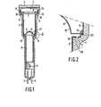
- the longitudinal sectional view of the prior art television camera tube shown in Figure 1 comprises a glass envelope 1 which is sealed at one end by a glass window 2 having a target 3.
- An electron gun 4 to which the desired electric voltages can be applied via a number of lead- through pins 5 is present in the tube.
- the inner wall of the envelope 1 is coated with a thin layer of nickel 6 by means of a known process, for example electroless nickel-plating.
- the tube furthermore comprises a gauze electrode 7 and a diaphragm 8 having an aperture 9 through which an electron beam generated by the electron gun 4 passes before it lands on the photo-sensitive layer 3.
- the nickel layer 6 is interrupted in the proximity of the gauze electrode 7 and the diaphragm 8, so that said layer is separated into three parts.
- Each of these parts forms a wall electrode which contributes to the formation of a target desired as regards shape and dimensions of the electron beam on the photo-sensitive layer 3.
- the inside diameter of the envelope 1 at the area of the gauze electrode 7 and the diaphragm 8 decreases stepwise.
- Each of these reductions takes place in a first step 12, 120 and a second step 13, 130.
- the first steps 12 and 120 respectively, constitute a supporting surface for the gauze electrode 7 and the diaphragm 8, respectively.
- the interruptions 10 and 11 are provided on a wall portion of the second steps 13 and 130, respectively. These interruptions have been obtained by locally grinding away the wall coating 6.
- the location of the interruptions 10 and 11 on the steps 13 and 130 has for its result that, electron-optically, they cannot exert any disturbing influence on the form and the direction of the electron beam.
- the gauze electrode 7 and the diaphragm 8 are mechanically and electrically connected to the nickel layer 6 by deformed spheres 16, 17 of indium which are positioned on the sides remote from the supporting surfaces. As the spheres of indium 16,17 are present in a field-free space they cannot exert any disturbing influence either on the form or on the direction of the electron beam.
- Figure 2 shows a detail of Figure 1 in a cross- sectional view.
- the diaphragm 8 is manufactured by deep drawing from 0.5 mm thick NiCr (80/20%) sheet material. If the spherical part 18 of the diaphragm present near the interruption 11 is not very truly circular, astigmatism is introduced into the electron beam.
- the parts of the electrically conductive wall coating (the nickel layer 6) separated by the interruption form an electron lens by applying a suitable voltage, which lens is made astigmatic by a non-spherical part 18.
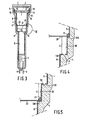
- the television camera tube according to the invention shown in the longitudinal sectional view of Figure 3 has a flat diaphragm 20 with central aperture 21 present at a distance of 7.5 mm from the interruption 11.
- the diameter D of the envelope portion between the two steps is 15.5 mm.
- the results of this location of the diaphragm with respect to the interruption is that at the area of the aperture 21 the axial field strength is considerably lower than at the area of the interruption, so that the spherical aberration of the electron lens is kept small.
- the envelope is manufactured by drawing a glass tube on a mandril so that the wall coating 60 between the first step 120 and the second step 130 (see also the detail of Figure 4) constitutes a substantially true circular cylinder with the result that the axial astigmatism which rather frequently occurs in the known diaphragms, is substantially avoided.
- the distance d must be between 0.4 D and D, D being the diameter of the envelope between the first step 120 and the second step 130, because the location of the diaphragm according to the prior art then is best approached.
- the remaining reference numerals refer to the same parts as described with reference to Figure 1, and for the sake of brevity will not be described again.
Landscapes
- Vessels, Lead-In Wires, Accessory Apparatuses For Cathode-Ray Tubes (AREA)
- Image-Pickup Tubes, Image-Amplification Tubes, And Storage Tubes (AREA)
Claims (1)
- Tube de prise de vues de télévision muni d'une partie d'enveloppe tubulaire pratiquement à symétrie de révolution en verre (1) comportant un revêtement de paroi conducteur (6) appliqué à l'intérieur, eun diaphragme perforé (20) étant supporté dans la partie d'enveloppe par une surface de support (120) s'étendant transversalement à l'axe longitudinal de la partie d'enveloppe, ladite surface de support étant formée par un changement pratiquement en forme de pas de la dimension transversale interne de la partie d'enveloppe et le revêtement conducteur (6) étant interrompu à une distance du diaphragme, le changement en forme de pas de la dimension transversale interne de la partie d'enveloppe comprenant au moins un premier pas (120) et un deuxième pas (130), le premier pas formant la surface de support pour le diaphragme, l'interruption (11) dans la revêtement de paroi conducteur étant réalisée sur une partie de paroi (130) du deuxième pas perpendiculaire audit axe longitudinal, caractérisé en ce que le diaphragme est une plaque plane et la distance axiale d comprise entre le premier pas et le deuxième pas se situe entre 0,4 D et D, D étant le diamètre interne constant de la partie d'enveloppe entre le premier pas et le deuxième pas.
Applications Claiming Priority (2)
| Application Number | Priority Date | Filing Date | Title |
|---|---|---|---|
| NL8401445A NL8401445A (nl) | 1984-05-07 | 1984-05-07 | Televisiekamerabuis. |
| NL8401445 | 1984-05-07 |
Publications (2)
| Publication Number | Publication Date |
|---|---|
| EP0163334A1 EP0163334A1 (fr) | 1985-12-04 |
| EP0163334B1 true EP0163334B1 (fr) | 1988-10-19 |
Family
ID=19843908
Family Applications (1)
| Application Number | Title | Priority Date | Filing Date |
|---|---|---|---|
| EP85200642A Expired EP0163334B1 (fr) | 1984-05-07 | 1985-04-24 | Tube de prise de vues de télévision |
Country Status (6)
| Country | Link |
|---|---|
| US (1) | US4607190A (fr) |
| EP (1) | EP0163334B1 (fr) |
| JP (1) | JPS60240030A (fr) |
| CA (1) | CA1226892A (fr) |
| DE (1) | DE3565746D1 (fr) |
| NL (1) | NL8401445A (fr) |
Families Citing this family (2)
| Publication number | Priority date | Publication date | Assignee | Title |
|---|---|---|---|---|
| NL8500340A (nl) * | 1985-02-07 | 1986-09-01 | Philips Nv | Televisiekamerabuis. |
| GB8707170D0 (en) * | 1987-03-25 | 1987-04-29 | Philips Nv | Electron beam device |
Family Cites Families (4)
| Publication number | Priority date | Publication date | Assignee | Title |
|---|---|---|---|---|
| US2828433A (en) * | 1956-04-25 | 1958-03-25 | Gen Dynamics Corp | Electron gun construction |
| GB1449570A (en) * | 1974-05-16 | 1976-09-15 | English Electric Valve Co Ltd | Photoconductive camera tubes |
| NL7807758A (nl) * | 1978-07-20 | 1980-01-22 | Philips Nv | Televisieopneembuis. |
| NL7807756A (nl) * | 1978-07-20 | 1980-01-22 | Philips Nv | Werkwijze voor het vervaardigen van een kathodestraal- buis en kathodestraalbuis vervaardigd volgens deze werkwijze. |
-
1984
- 1984-05-07 NL NL8401445A patent/NL8401445A/nl not_active Application Discontinuation
- 1984-10-31 US US06/666,810 patent/US4607190A/en not_active Expired - Fee Related
-
1985
- 1985-04-24 EP EP85200642A patent/EP0163334B1/fr not_active Expired
- 1985-04-24 DE DE8585200642T patent/DE3565746D1/de not_active Expired
- 1985-05-02 CA CA000480637A patent/CA1226892A/fr not_active Expired
- 1985-05-04 JP JP60095860A patent/JPS60240030A/ja active Pending
Also Published As
| Publication number | Publication date |
|---|---|
| NL8401445A (nl) | 1985-12-02 |
| EP0163334A1 (fr) | 1985-12-04 |
| JPS60240030A (ja) | 1985-11-28 |
| CA1226892A (fr) | 1987-09-15 |
| US4607190A (en) | 1986-08-19 |
| DE3565746D1 (en) | 1988-11-24 |
Similar Documents
| Publication | Publication Date | Title |
|---|---|---|
| EP0203805B1 (fr) | Canon à électrons | |
| US4853589A (en) | Electron beam device having an electron gun and a method of making the electron gun | |
| US4276494A (en) | Cathode ray tube with transversely supported electrode and conductive wall coating | |
| US4169239A (en) | Electrostatically focusing type image pickup tubes and method of manufacturing the same | |
| US4721882A (en) | Cathode ray tube | |
| EP0378268B1 (fr) | Tube image | |
| EP0163334A1 (fr) | Tube de prise de vues de télévision | |
| US4432738A (en) | Camera tube and method of manufacturing same | |
| US3176181A (en) | Apertured coaxial tube quadripole lens | |
| US4567399A (en) | Cathode ray tube with spherical aberration correction means | |
| US5202606A (en) | Cathode-ray tube with focussing structure and getter means | |
| US4868455A (en) | Electron beam device with an electron gun having a tubular insulating electrode support | |
| EP0083459A1 (fr) | Tube de prise de vues de télévision | |
| US4173727A (en) | Electron image device | |
| US3396297A (en) | Multiple electron gun structure for cathode ray tube | |
| KR100366088B1 (ko) | 헬리컬 다단렌즈 전극 구조체를 가지는 음극선관 전자총 | |
| US3509609A (en) | Means for assembling a multiple electron gun structure for cathode ray tube | |
| EP0378269B1 (fr) | Tube image | |
| GB2146171A (en) | Cathode ray tubes | |
| KR100337877B1 (ko) | 렌즈 수차를 감소시키는 음극선관 전자총의 다단렌즈 전극구조 | |
| GB2295267A (en) | Getter spring and cathode-ray tube using getter spring | |
| KR100294505B1 (ko) | 컬러 음극선관용 전자총의 전극 | |
| JPS60101847A (ja) | 像増強管 | |
| JPH0731985B2 (ja) | 陰極線管電子銃構体 | |
| JPS60240032A (ja) | 陰極線管 |
Legal Events
| Date | Code | Title | Description |
|---|---|---|---|
| PUAI | Public reference made under article 153(3) epc to a published international application that has entered the european phase |
Free format text: ORIGINAL CODE: 0009012 |
|
| AK | Designated contracting states |
Designated state(s): DE FR GB IT |
|
| 17P | Request for examination filed |
Effective date: 19860527 |
|
| 17Q | First examination report despatched |
Effective date: 19871006 |
|
| GRAA | (expected) grant |
Free format text: ORIGINAL CODE: 0009210 |
|
| AK | Designated contracting states |
Kind code of ref document: B1 Designated state(s): DE FR GB IT |
|
| REF | Corresponds to: |
Ref document number: 3565746 Country of ref document: DE Date of ref document: 19881124 |
|
| ITF | It: translation for a ep patent filed | ||
| ET | Fr: translation filed | ||
| PLBE | No opposition filed within time limit |
Free format text: ORIGINAL CODE: 0009261 |
|
| STAA | Information on the status of an ep patent application or granted ep patent |
Free format text: STATUS: NO OPPOSITION FILED WITHIN TIME LIMIT |
|
| 26N | No opposition filed | ||
| PGFP | Annual fee paid to national office [announced via postgrant information from national office to epo] |
Ref country code: GB Payment date: 19900331 Year of fee payment: 6 |
|
| PGFP | Annual fee paid to national office [announced via postgrant information from national office to epo] |
Ref country code: FR Payment date: 19900424 Year of fee payment: 6 |
|
| ITTA | It: last paid annual fee | ||
| PGFP | Annual fee paid to national office [announced via postgrant information from national office to epo] |
Ref country code: DE Payment date: 19900622 Year of fee payment: 6 |
|
| PG25 | Lapsed in a contracting state [announced via postgrant information from national office to epo] |
Ref country code: GB Effective date: 19910424 |
|
| GBPC | Gb: european patent ceased through non-payment of renewal fee | ||
| PG25 | Lapsed in a contracting state [announced via postgrant information from national office to epo] |
Ref country code: FR Effective date: 19911230 |
|
| PG25 | Lapsed in a contracting state [announced via postgrant information from national office to epo] |
Ref country code: DE Effective date: 19920201 |
|
| REG | Reference to a national code |
Ref country code: FR Ref legal event code: ST |