EP0163337B1 - Entladevorrichtung für einen Silo - Google Patents
Entladevorrichtung für einen Silo Download PDFInfo
- Publication number
- EP0163337B1 EP0163337B1 EP85200677A EP85200677A EP0163337B1 EP 0163337 B1 EP0163337 B1 EP 0163337B1 EP 85200677 A EP85200677 A EP 85200677A EP 85200677 A EP85200677 A EP 85200677A EP 0163337 B1 EP0163337 B1 EP 0163337B1
- Authority
- EP
- European Patent Office
- Prior art keywords
- discharge
- plates
- conveyor
- collar
- scraper device
- Prior art date
- Legal status (The legal status is an assumption and is not a legal conclusion. Google has not performed a legal analysis and makes no representation as to the accuracy of the status listed.)
- Expired
Links
- 238000009434 installation Methods 0.000 title claims abstract description 23
- 238000005192 partition Methods 0.000 claims description 10
- 238000007790 scraping Methods 0.000 claims description 6
- 239000013590 bulk material Substances 0.000 abstract description 6
- 239000000463 material Substances 0.000 description 20
- 239000003245 coal Substances 0.000 description 2
- 238000000280 densification Methods 0.000 description 2
- 101100400378 Mus musculus Marveld2 gene Proteins 0.000 description 1
- 230000001174 ascending effect Effects 0.000 description 1
- 230000001680 brushing effect Effects 0.000 description 1
- 230000001627 detrimental effect Effects 0.000 description 1
- 238000007599 discharging Methods 0.000 description 1
- 230000000694 effects Effects 0.000 description 1
- 230000002093 peripheral effect Effects 0.000 description 1
- 230000000284 resting effect Effects 0.000 description 1
- 238000003466 welding Methods 0.000 description 1
Images


Classifications
-
- B—PERFORMING OPERATIONS; TRANSPORTING
- B65—CONVEYING; PACKING; STORING; HANDLING THIN OR FILAMENTARY MATERIAL
- B65G—TRANSPORT OR STORAGE DEVICES, e.g. CONVEYORS FOR LOADING OR TIPPING, SHOP CONVEYOR SYSTEMS OR PNEUMATIC TUBE CONVEYORS
- B65G65/00—Loading or unloading
- B65G65/30—Methods or devices for filling or emptying bunkers, hoppers, tanks, or like containers, of interest apart from their use in particular chemical or physical processes or their application in particular machines, e.g. not covered by a single other subclass
- B65G65/34—Emptying devices
- B65G65/36—Devices for emptying from the top
- B65G65/365—Devices for emptying from the top comprising a vertical passage located inside the container
Definitions
- the invention relates to a discharge installation for a silo, comprising a column of vertically spaced collar plates each having an outer and an inner edge, said plates being disposed one above the other with a clearance externally leaving an open passage along the entire circumferential outer edges of each pair of adjacent plates and internally enclosing a central space bounded by the inner edges of said collar plates forming a vertical discharge duct.
- a discharge installation is known from DE-A 1.914.600.
- the collar plates are provided with holes through which rods are fitted so as to form a column with said plates.
- This document also discloses a discharge installation wherein the column is formed by helical collar plates.
- each collar plate with a short hanging skirt along its outer circumference so that the stored material when being discharged must pass through a relatively narrowed passage between said skirt and the collar plate whereupon the material will get more room once lying upon the collar plate while moving to the discharge duct.
- the object of the invention is to eliminate this drawback and to provide a discharge installation for a silo affording all bulk materials to be stored in the silo to be discharged without the occurrence of clogging, arching or caking due to densification in the space between the collar plates.
- the object is attained according to the invention by using a discharge installation of the type described at the beginning which is characterized in that the clearance between adjacent collar plates comprise a scraper device capable of performing at least two individual separate movements: a scraping action mainly in central direction towards the'vertical discharge duct in combination with a revolving movement through a path of travel around said vertical discharge duct.
- DE-C-297 109 discloses a discharge installation for a silo comprising a column of vertically spaced collar plates.
- a scraper device exerts a scraping action towards a vertical discharge opening.
- This scraping action is performed in circumferential direction and not in central direction.
- the collar plates show an excen- tric hole the scraper device brushing the material over this hole.
- two sectors in the connection between-the silo and the column of collar plates remain outside the action of the scraper device and thus tend to be gradually closed by densifying or consolidating material.
- the invention is particularly suitable for a discharge installation wherein, in the upward direction of the column, the clearances between the collar plates disposed one above the other merge into one another.
- This merging might be attained by having the collar plates run as a helix or in the case of horizontal collar plates by providing in a portion thereof an upward inclination leading to the collar plate disposed above it.
- the scraper device in addition to its capability of revolving about the discharge duct, is also able to perform a vertical movement, in conjunction with the revolving movement in order to pass through the successive clearances merging into one another. It is then worthwhile for the scraper device to cooperate with a known radial distribution and discharge conveyor provided for the bulk material in the silo and rotating about the column.
- the scraper device consists of a separate conveyor worm the helical blade of which lies with its lower side near the upper face of a collar plate.
- the scraper device is embodied as a conveyor worm forming part of one or several conveyor screws of the distribution and discharge conveyor.
- the invention also relates to a column comprising vertically spaced collar plates each having an outer and an inner edge, said plates being disposed one above the other with a clearance externally leaving an open passage along the entire circumferential outer edges of each pair of adjacent plates and internally enclosing a central space bounded by the inner edges of said collar plates forming a vertical discharge duct to be used for the discharge installation as described above.
- a scraper device in the clearance between successive plates, said scraper device being capable of performing at least two individual separate movements: a scraping action mainly in central direction towards the vertical discharge duct in combination with a revolving movement through a path of travel around said vertical discharge duct, said collar plates being fixed with their inner edges facing the discharge duct to one or several partitions extending through said discharge duct.
- the column will be particularly suitable for coal to be stored in the silo. It is then worthwhile that within or in the vicinity of the central discharge duct there is provided a guide for one end of the scraper device.
- the invention furthermore relates to a silo comprising a distribution and discharge conveyor provided with a discharge installation as mentioned above.
- a silo is characterized in that the shape of the collar plates and the vertical component of motion of the distribution and discharge conveyor being adapted to each other.
- a cylindrical wall 2, externally supported by columns 3, is placed upon a foundation 1 in a known manner.
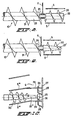
- a column 4 of collar plates 5 disposed one above the other with proper interspacing and enclosing a space 6 forming a central vertical discharge duct.
- the material to be stored passes via a funnel 7, a filling device 8 of a known design and a telescoping shaft 9 to a point above the distribution and discharge conveyor 10 known per se.
- This conveyor may consist of one or several screw conveyors and runs directly over the material already stored in the silo.
- the conveyor is then suspended from cables 11 on a carrier 12 rotating in the silo. By retracting the cables 11, the conveyor 10 can be lifted upwards.
- the conveyor 10 so passed through the entire space within the silo about the column 4 in a horizontal plane.
- the rotation of the screw conveyor 10 in one direction causes the material to be gradually distributed over the total surface.
- the rotation of the screw conveyor 10 in the opposite direction causes the material to be scraped in the direction of the column 4 and, passing between the collar plates 5, shot down the vertical discharge duct 6.
- the conveyor When the conveyor is rotating, it passes through an ascending helical plane when filling, and the conveyor passes through a descending helical plane when discharging said material.
- the columnh -4 is adapted to this operation in that the collar plates 5 are likewise of a helical design, as is seen more clearly in Figure 2.
- the collar plates are fixed with the edge 14 thereof facing the discharge duct 6 to one or several partitions 15 running through the discharge duct.
- the partitions 15 need not run vertically, but may be in the form of a helical chute as indicated in Figure 5 by the reference numeral 16. In radial direction, there is no need for the partition in the form of a chute to be plane, but it may be bent upwards in radial direction, so that the bulk material sliding down is not thrown between the collar plates 5 as a result of the centrifugal force.
- Such an embodiment is especialy suitable for materials subjected to wear due to colliding with each other, such as for instance coal.
- the sliding action to which this material is subjected has proved to be less detrimental to the such material than the effect of the mutual collision of the grains or pieces of material.
- the cores reach into the clearance between two neighboring collar plates 5, and are provided with a separate worm blade 20.
- This situation is likewise diagrammatically shown in Figure 7.
- the former can also be located at any point above the conveyor in the next clearance, as is diagrammatically indicated in Figure 7 by the reference numeral 19'.
- the separate, conveyor screw 19 has a cylindrical core 22 and the same applies to the core 23 of the conveyor 10. Both conveyors are supported in a bearing 24 suspended in the cable 11.
- the core 22' of the screw conveyor 20 is cone-shaped, which has the advanage of precluding the risk of bulk material accumulating upon the plate 5, since the screw conveyor 20 is directed radially inwards towards the center of the vertical discharge duct.
- the screw conveyor 21 of the distribution and discharge conveyor 10 is suspended from the cable 11.
- the blades of the scraper device in the form of the screw conveyor 20 follow the conicity of the core 22".
- the inclination of the collar plates 5"' is then adapted to said conicity.
- the core 22" extends into the vertical discharge duct 6 and carries a guide roller 25 resting upon a guide 26 in the form of a rail.
- the guide 26 is supported on brackets 28 fastened to a rod 27 and also carrying supports for the collar plates 5"'.
- a scraper or brush (not shown). It is evident that a guide similar to a rail 26 can also be provided on the inside against the wall of the silo whereupon the distribution and discharge conveyor 10 can be guided as.well.
- one of the conveyor screws 17,21 in conjunction with the screw conveyors 19, 20 in the form of a scraper device associated therewith travel tangentially over the collar plates 5.
Landscapes
- Engineering & Computer Science (AREA)
- Mechanical Engineering (AREA)
- Filling Or Emptying Of Bunkers, Hoppers, And Tanks (AREA)
- Crystals, And After-Treatments Of Crystals (AREA)
- Feeding, Discharge, Calcimining, Fusing, And Gas-Generation Devices (AREA)
Claims (10)
Priority Applications (1)
| Application Number | Priority Date | Filing Date | Title |
|---|---|---|---|
| AT85200677T ATE40335T1 (de) | 1984-05-02 | 1985-05-01 | Entladevorrichtung fuer einen silo. |
Applications Claiming Priority (2)
| Application Number | Priority Date | Filing Date | Title |
|---|---|---|---|
| NL8401399A NL8401399A (nl) | 1984-05-02 | 1984-05-02 | Afvoerinrichting voor een silo. |
| NL8401399 | 1984-05-02 |
Publications (2)
| Publication Number | Publication Date |
|---|---|
| EP0163337A1 EP0163337A1 (de) | 1985-12-04 |
| EP0163337B1 true EP0163337B1 (de) | 1989-01-25 |
Family
ID=19843885
Family Applications (1)
| Application Number | Title | Priority Date | Filing Date |
|---|---|---|---|
| EP85200677A Expired EP0163337B1 (de) | 1984-05-02 | 1985-05-01 | Entladevorrichtung für einen Silo |
Country Status (5)
| Country | Link |
|---|---|
| US (1) | US4645403A (de) |
| EP (1) | EP0163337B1 (de) |
| AT (1) | ATE40335T1 (de) |
| DE (1) | DE3567839D1 (de) |
| NL (1) | NL8401399A (de) |
Families Citing this family (8)
| Publication number | Priority date | Publication date | Assignee | Title |
|---|---|---|---|---|
| DE3427410C1 (de) * | 1984-07-25 | 1986-02-06 | Jörg Wolfgang 4130 Moers Buddenberg | Silo mit kreisrundem Grundriss fuer Schuettgueter und einem an einer Stuetzsaeule heb- und senkbar angeordneten Querfoerderer |
| DE3514888A1 (de) * | 1985-04-25 | 1986-11-06 | Gustav Schade Maschinenfabrik Gmbh & Co, 4600 Dortmund | Einrichtung zur schuettgutfoerderung in silos |
| DE3606669A1 (de) * | 1986-02-28 | 1987-09-03 | Schade Maschf Gustav | Ausspeichereinrichtung fuer silos |
| DE3937683A1 (de) * | 1989-11-13 | 1991-05-16 | Veba Kraftwerke Ruhr | Vorrichtung zum entleeren von schuettgut enthaltenden silos |
| US5112180A (en) * | 1991-01-22 | 1992-05-12 | Hough International, Inc. | Silo top unloader |
| WO2004023242A2 (en) * | 2002-09-03 | 2004-03-18 | South, Phillip, Barry | Transfer terminal with surge bin |
| US7127854B2 (en) * | 2003-02-13 | 2006-10-31 | Hedrick Thomas W | Bulk material storage facilities with access chases and/or internal filling structures |
| US8770388B1 (en) | 2011-10-19 | 2014-07-08 | Duane Cyril Chaon | Sweep conveyor for removal of grain and other materials from bins |
Family Cites Families (10)
| Publication number | Priority date | Publication date | Assignee | Title |
|---|---|---|---|---|
| DE297109C (de) * | ||||
| US1867462A (en) * | 1932-01-14 | 1932-07-12 | Gifford Wood Co | Discharge chute for storage bins |
| FR1032110A (fr) * | 1950-03-16 | 1953-06-30 | Escher Wyss Ag | Appareil à vider les silos destinés à l'entassement de la glace en petits morceaux |
| FR1234986A (fr) * | 1958-09-17 | 1960-07-01 | Geratebau Schwarting K G | Dispositif de stockage, notamment pour produits agricoles tels que le foin et les céréales hachées |
| GB1091284A (en) * | 1963-11-07 | 1967-11-15 | Norton Harty Engineering Compa | Improvements in or relating to bunkers |
| US3358856A (en) * | 1966-04-25 | 1967-12-19 | Ingeniors N Nils Weibull Ab Fa | Silo unloading device |
| DE1780062A1 (de) * | 1968-07-27 | 1971-11-25 | Teldix Gmbh | Antiblockierregelsystem mit einer Einrichtung zur Gewinnung der Steuersignale aus einer Tachospannung |
| SE312768B (de) * | 1968-09-25 | 1969-07-21 | K Ivstedt | |
| CH607825A5 (de) * | 1976-04-15 | 1978-11-15 | Sulzer Ag | |
| US4138021A (en) * | 1977-07-25 | 1979-02-06 | Purdue Research Foundation | Ducted material handling device for top unloading of a storage receptacle |
-
1984
- 1984-05-02 NL NL8401399A patent/NL8401399A/nl not_active Application Discontinuation
-
1985
- 1985-05-01 DE DE8585200677T patent/DE3567839D1/de not_active Expired
- 1985-05-01 EP EP85200677A patent/EP0163337B1/de not_active Expired
- 1985-05-01 US US06/729,286 patent/US4645403A/en not_active Expired - Fee Related
- 1985-05-01 AT AT85200677T patent/ATE40335T1/de not_active IP Right Cessation
Also Published As
| Publication number | Publication date |
|---|---|
| NL8401399A (nl) | 1985-12-02 |
| ATE40335T1 (de) | 1989-02-15 |
| DE3567839D1 (en) | 1989-03-02 |
| US4645403A (en) | 1987-02-24 |
| EP0163337A1 (de) | 1985-12-04 |
Similar Documents
| Publication | Publication Date | Title |
|---|---|---|
| US3945537A (en) | Discharge device for a bunker | |
| US5176295A (en) | Discharge apparatus for bins | |
| US4662508A (en) | Product feeding device for combination weighing machine | |
| US4645403A (en) | Discharge installation for a silo | |
| JPH1087046A (ja) | 砕砂製造設備のベルトコンベヤ | |
| US4415102A (en) | Device for emptying a round bulk-material silo | |
| US3949888A (en) | Silo, especially for heavy flowing chemical and mineral substances | |
| US5635065A (en) | Shavings centrifuge | |
| US3278054A (en) | Bunker and spiral chute loading means | |
| US4518498A (en) | Metallurgical slag filtering apparatus which effects uniform charging of a conveyer belt | |
| US3780888A (en) | Material transfer apparatus for a rotary drum | |
| US2728470A (en) | Hopper construction | |
| US2709537A (en) | Feeding apparatus for belt conveyers and the like | |
| JPS6341322A (ja) | ばら物のサイロ装置 | |
| GB2104402A (en) | Apparatus for removing solid material from sewage | |
| CA2032622A1 (en) | Silo with a discharge means | |
| US2855128A (en) | Counter with rotating device | |
| JPS61502743A (ja) | ばら荷用の円形の輪郭部と支持柱に昇降可能に配置された横方向コンベヤと有するサイロ | |
| RU2058197C1 (ru) | Ротационно-вероятностный грохот | |
| SU1719831A1 (ru) | Карусельна сушилка | |
| US2915181A (en) | Apparatus for use in classifying or both classifying and drying loose material | |
| JPS5895038A (ja) | サイロの円周払い出し装置 | |
| US3820672A (en) | Device for discharging material from a silo | |
| US2738886A (en) | Cooling device | |
| EP0345849B1 (de) | Entladevorrichtung |
Legal Events
| Date | Code | Title | Description |
|---|---|---|---|
| PUAI | Public reference made under article 153(3) epc to a published international application that has entered the european phase |
Free format text: ORIGINAL CODE: 0009012 |
|
| AK | Designated contracting states |
Designated state(s): AT BE CH DE FR GB IT LI LU NL SE |
|
| 17P | Request for examination filed |
Effective date: 19860528 |
|
| 17Q | First examination report despatched |
Effective date: 19861222 |
|
| D17Q | First examination report despatched (deleted) | ||
| GRAA | (expected) grant |
Free format text: ORIGINAL CODE: 0009210 |
|
| AK | Designated contracting states |
Kind code of ref document: B1 Designated state(s): AT BE CH DE FR GB IT LI LU NL SE |
|
| PG25 | Lapsed in a contracting state [announced via postgrant information from national office to epo] |
Ref country code: SE Effective date: 19890125 Ref country code: LI Effective date: 19890125 Ref country code: IT Free format text: LAPSE BECAUSE OF FAILURE TO SUBMIT A TRANSLATION OF THE DESCRIPTION OR TO PAY THE FEE WITHIN THE PRESCRIBED TIME-LIMIT;WARNING: LAPSES OF ITALIAN PATENTS WITH EFFECTIVE DATE BEFORE 2007 MAY HAVE OCCURRED AT ANY TIME BEFORE 2007. THE CORRECT EFFECTIVE DATE MAY BE DIFFERENT FROM THE ONE RECORDED. Effective date: 19890125 Ref country code: FR Free format text: THE PATENT HAS BEEN ANNULLED BY A DECISION OF A NATIONAL AUTHORITY Effective date: 19890125 Ref country code: CH Effective date: 19890125 Ref country code: AT Effective date: 19890125 |
|
| REF | Corresponds to: |
Ref document number: 40335 Country of ref document: AT Date of ref document: 19890215 Kind code of ref document: T |
|
| REF | Corresponds to: |
Ref document number: 3567839 Country of ref document: DE Date of ref document: 19890302 |
|
| REG | Reference to a national code |
Ref country code: CH Ref legal event code: PL |
|
| PG25 | Lapsed in a contracting state [announced via postgrant information from national office to epo] |
Ref country code: LU Free format text: LAPSE BECAUSE OF NON-PAYMENT OF DUE FEES Effective date: 19890531 |
|
| EN | Fr: translation not filed | ||
| PLBE | No opposition filed within time limit |
Free format text: ORIGINAL CODE: 0009261 |
|
| STAA | Information on the status of an ep patent application or granted ep patent |
Free format text: STATUS: NO OPPOSITION FILED WITHIN TIME LIMIT |
|
| 26N | No opposition filed | ||
| PGFP | Annual fee paid to national office [announced via postgrant information from national office to epo] |
Ref country code: GB Payment date: 19900411 Year of fee payment: 6 |
|
| PG25 | Lapsed in a contracting state [announced via postgrant information from national office to epo] |
Ref country code: GB Effective date: 19910501 |
|
| PGFP | Annual fee paid to national office [announced via postgrant information from national office to epo] |
Ref country code: NL Payment date: 19910531 Year of fee payment: 7 |
|
| PGFP | Annual fee paid to national office [announced via postgrant information from national office to epo] |
Ref country code: DE Payment date: 19911129 Year of fee payment: 7 |
|
| PGFP | Annual fee paid to national office [announced via postgrant information from national office to epo] |
Ref country code: BE Payment date: 19911217 Year of fee payment: 7 |
|
| GBPC | Gb: european patent ceased through non-payment of renewal fee | ||
| PG25 | Lapsed in a contracting state [announced via postgrant information from national office to epo] |
Ref country code: BE Effective date: 19920531 |
|
| BERE | Be: lapsed |
Owner name: DE WIT CORNELIS LEENDERT Effective date: 19920531 |
|
| PG25 | Lapsed in a contracting state [announced via postgrant information from national office to epo] |
Ref country code: NL Effective date: 19921201 |
|
| NLV4 | Nl: lapsed or anulled due to non-payment of the annual fee | ||
| PG25 | Lapsed in a contracting state [announced via postgrant information from national office to epo] |
Ref country code: DE Effective date: 19930202 |