EP0163360A2 - Connecteur consistant en deux parties - Google Patents
Connecteur consistant en deux parties Download PDFInfo
- Publication number
- EP0163360A2 EP0163360A2 EP85300699A EP85300699A EP0163360A2 EP 0163360 A2 EP0163360 A2 EP 0163360A2 EP 85300699 A EP85300699 A EP 85300699A EP 85300699 A EP85300699 A EP 85300699A EP 0163360 A2 EP0163360 A2 EP 0163360A2
- Authority
- EP
- European Patent Office
- Prior art keywords
- parts
- stud
- bushing
- key
- projections
- Prior art date
- Legal status (The legal status is an assumption and is not a legal conclusion. Google has not performed a legal analysis and makes no representation as to the accuracy of the status listed.)
- Withdrawn
Links
Images
Classifications
-
- F—MECHANICAL ENGINEERING; LIGHTING; HEATING; WEAPONS; BLASTING
- F16—ENGINEERING ELEMENTS AND UNITS; GENERAL MEASURES FOR PRODUCING AND MAINTAINING EFFECTIVE FUNCTIONING OF MACHINES OR INSTALLATIONS; THERMAL INSULATION IN GENERAL
- F16B—DEVICES FOR FASTENING OR SECURING CONSTRUCTIONAL ELEMENTS OR MACHINE PARTS TOGETHER, e.g. NAILS, BOLTS, CIRCLIPS, CLAMPS, CLIPS OR WEDGES; JOINTS OR JOINTING
- F16B21/00—Means for preventing relative axial movement of a pin, spigot, shaft or the like and a member surrounding it; Stud-and-socket releasable fastenings
- F16B21/06—Releasable fastening devices with snap-action
Definitions
- the present invention relates to a two-part connector and more particularly, though not exclusively, a connector for mounting an article on a body, for example a blind or visor on a window.
- Known connectors for such purposes comprise a stud part for insertion in a bushing part to engage projections on one part behind abutments on the other part.
- the connector can be released by giving one of the parts a sharp pull greater than the normal holding force, for which the connector is designed.
- Blinds for windows are normally mounted by means of a bayonet connector which for locking and unlocking requires rotation of one of the parts through 90 degrees.
- a tool is required but this may, however, be as simple as a coin.
- a two-part connector comprises a bushing part and a stud part for insertion in the bushing part to engage one or more projections on one part behind one or more abutments on the other, by resilient deformation of at least one of the parts, the parts being resiliently deformable to disengage the projections and/or abutments enabling separation of the two parts, by inserting a tubular key into an annular opening defining between the two parts.
- the tubular key preferably has a predetermined internal and external diameter.
- To separate the parts of the connector is a simple operation requiring only insertion of the key, by which at least one of the parts, more particularly, the or each projection is deformed or displaced so as to disengage the interlocking projection(s) and abutment(s). This allows one of the parts to be readily removed from the other.
- the tubular key is simple and rugged, but cannot be replaced by any other objects with a differing shape or diameter.
- the key is unlike objects normally found in people's pockets such as coins, door keys and the like. The connector is thereby to a certain degree protected against unauthorised unlocking.
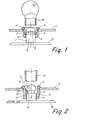
- the mounting connector shown in Figure 1 comprises two parts 1, 2 each of which is adapted to be fastened to one of the two bodies that are to be held together.
- the connector is especially suited for securing a blind or an auto visor (usually manufactured from a plastic sheet by vacuum forming) to the rear window of a motor car.
- the part 1 in the form of a stud 7 is mounted on the window by gluing or alternatively to the bodywork of the car by means of selftapping screws.
- the other part 2, in the form of a bushing is inserted through an opening in the plastic sheet 3, and has a collar adapted to engage the edge of the opening.
- an annular projection 6 is provided which is able to slide onto part 1.
- the stud part 1 has an integral base plate 8, by means of which the part 1 is fastened to the body.
- the free end of the stud is rounded in order to facilitate insertion of the stud 7 in the part 2.
- a slotted ring 10 In an annular groove 9 around the stud 7 is inserted a slotted ring 10 forming an undercut collar on the stud.
- the outer diameter of the slotted ring 10 is larger than that of the stud 7, but its internal diameter is smaller than the diameter of the stud.
- the ring 10 is resilient and has a chamfer on the top of its outer edge, so that when the part 2 is placed onto the stud 7, the ring 10 is pressed into the groove 9 which is sufficiently deep to receive the entire ring 10, allowing the projection 6 to pass the ring.
- the ring 9 snaps back and locks the part 2. If it is desired to disassemble the two parts 1 and 2, a tube shaped key 12, the inner diameter of which corresponds to the outer diameter of the stud 7 and the outer diameter of which corresponds to the inner diameter of the tubular portion of the part 2, is inserted into the annular gap between the two parts. The key 12 will then press the ring 10 into the groove 9, allowing the part 2 to be lifted off.
- a tubular key 12 is inserted_between the two parts, the key pressing the tongues outwards owing to the chamfered upper portion 15 of the tongues 13 into a recess 16 arranged behind the tongues.
- the key 12 and the part 2 may then be removed from the stud 7.
Landscapes
- Engineering & Computer Science (AREA)
- General Engineering & Computer Science (AREA)
- Mechanical Engineering (AREA)
- Snaps, Bayonet Connections, Set Pins, And Snap Rings (AREA)
- Connection Of Plates (AREA)
Applications Claiming Priority (2)
| Application Number | Priority Date | Filing Date | Title |
|---|---|---|---|
| DK48984A DK149903C (da) | 1984-02-03 | 1984-02-03 | Beslag af to genstande til hinanden og noegle til udloesning af beslaget |
| DK489/84 | 1984-02-03 |
Publications (2)
| Publication Number | Publication Date |
|---|---|
| EP0163360A2 true EP0163360A2 (fr) | 1985-12-04 |
| EP0163360A3 EP0163360A3 (fr) | 1986-09-03 |
Family
ID=8094138
Family Applications (1)
| Application Number | Title | Priority Date | Filing Date |
|---|---|---|---|
| EP85300699A Withdrawn EP0163360A3 (fr) | 1984-02-03 | 1985-02-01 | Connecteur consistant en deux parties |
Country Status (4)
| Country | Link |
|---|---|
| EP (1) | EP0163360A3 (fr) |
| JP (1) | JPS60184707A (fr) |
| AU (1) | AU3828985A (fr) |
| DK (1) | DK149903C (fr) |
Cited By (5)
| Publication number | Priority date | Publication date | Assignee | Title |
|---|---|---|---|---|
| FR2594502A1 (fr) * | 1986-02-17 | 1987-08-21 | Itw De France | Dispositif de fixation, notamment pour panneaux |
| EP0754602A1 (fr) * | 1995-07-21 | 1997-01-22 | Textron Inc. | Dispositif de montage de sac gonflable |
| GB2334298A (en) * | 1998-02-12 | 1999-08-18 | Piolax Inc | Trim clip with resilient latch |
| EP1209401A3 (fr) * | 2000-11-23 | 2004-05-12 | Josef Kühlmann | Méthode pour fabriquer un corps tubulaire dimensionnellement stable à partir d'une bande de matériau et connecteur pour fabriquer le corps tubulaire |
| GB2413589A (en) * | 2004-04-28 | 2005-11-02 | Newfrey Llc | Fastener clamping member between two flanges |
Family Cites Families (8)
| Publication number | Priority date | Publication date | Assignee | Title |
|---|---|---|---|---|
| DE7721719U1 (fr) * | N.V. Philips' Gloeilampenfabrieken, Eindhoven (Niederlande) | |||
| US3009381A (en) * | 1957-11-27 | 1961-11-21 | Illinois Tool Works | Stud and dished plastic fastening element |
| GB1036423A (en) * | 1961-10-13 | 1966-07-20 | Ft Products Ltd | An improved fastener |
| FR1363849A (fr) * | 1963-07-23 | 1964-06-12 | Carr Fastener Co Ltd | Dispositif de fermeture et moyens de fixation de celui-ci dans une ouverture ou cavité formée dans un support |
| DE1475035B2 (de) * | 1965-12-01 | 1971-02-04 | Paul Hellermann Gmbh, 2080 Pinneberg | Befestigungsvorrichtung |
| DE2609094A1 (de) * | 1975-12-03 | 1977-09-08 | Raymond A Fa | Verschlusselement |
| DE2626140A1 (de) * | 1976-06-11 | 1977-12-29 | Itw Ateco Gmbh | Befestigung fuer abdeckplatten |
| DD158885A1 (de) * | 1981-05-18 | 1983-02-09 | Bernd Borrmann | Sonnenschutzblende mit hinterlueftung |
-
1984
- 1984-02-03 DK DK48984A patent/DK149903C/da not_active IP Right Cessation
-
1985
- 1985-02-01 EP EP85300699A patent/EP0163360A3/fr not_active Withdrawn
- 1985-02-01 AU AU38289/85A patent/AU3828985A/en not_active Abandoned
- 1985-02-02 JP JP1775585A patent/JPS60184707A/ja active Pending
Cited By (8)
| Publication number | Priority date | Publication date | Assignee | Title |
|---|---|---|---|---|
| FR2594502A1 (fr) * | 1986-02-17 | 1987-08-21 | Itw De France | Dispositif de fixation, notamment pour panneaux |
| EP0754602A1 (fr) * | 1995-07-21 | 1997-01-22 | Textron Inc. | Dispositif de montage de sac gonflable |
| GB2334298A (en) * | 1998-02-12 | 1999-08-18 | Piolax Inc | Trim clip with resilient latch |
| GB2334298B (en) * | 1998-02-12 | 2000-01-19 | Piolax Inc | A part mounting structure |
| US6074150A (en) * | 1998-02-12 | 2000-06-13 | Piolax Inc. | Part mounting structure |
| EP1209401A3 (fr) * | 2000-11-23 | 2004-05-12 | Josef Kühlmann | Méthode pour fabriquer un corps tubulaire dimensionnellement stable à partir d'une bande de matériau et connecteur pour fabriquer le corps tubulaire |
| GB2413589A (en) * | 2004-04-28 | 2005-11-02 | Newfrey Llc | Fastener clamping member between two flanges |
| US7257867B2 (en) | 2004-04-28 | 2007-08-21 | Newfrey Llc | Clip for attaching two members |
Also Published As
| Publication number | Publication date |
|---|---|
| DK149903B (da) | 1986-10-20 |
| EP0163360A3 (fr) | 1986-09-03 |
| AU3828985A (en) | 1985-08-08 |
| DK149903C (da) | 1987-05-18 |
| DK48984D0 (da) | 1984-02-03 |
| JPS60184707A (ja) | 1985-09-20 |
| DK48984A (da) | 1985-08-04 |
Similar Documents
| Publication | Publication Date | Title |
|---|---|---|
| US4668145A (en) | Fastener for coupling together two panels in face-to-face relation | |
| US4828444A (en) | Plastic push-on nut | |
| US5588329A (en) | Snap together shift knob construction | |
| US5931035A (en) | Cylinder type lock arrangement | |
| US4542922A (en) | Fitting for connecting circumferentially ribbed insulating tubes of plastic | |
| US7360964B2 (en) | Joint structure | |
| US4176428A (en) | Panel fastener | |
| CA2040260A1 (fr) | Ensemble de garnitures pour vehicule et elements de fixation appropries | |
| US4932105A (en) | Self locking attaching system | |
| CN106979201B (zh) | 具有漏斗引导件的紧固件夹具组件 | |
| US6371619B1 (en) | Vehicle exterior mirror | |
| GB2298672A (en) | Protection against forced opening of vehicle door locks | |
| EP0163360A2 (fr) | Connecteur consistant en deux parties | |
| KR101133305B1 (ko) | 스티어링 록 조립체 | |
| EP0557082B1 (fr) | Pare-soleil pour véhicule | |
| US6227500B1 (en) | Meter mounting structure and meter mounting method | |
| US6178605B1 (en) | System for coupling and fixing plastic material accessories to modular self-supporting elements and the latter to the vehicle bodywork | |
| JP3423494B2 (ja) | 留め具 | |
| US4586736A (en) | Flush mounting cup for cabinet latch | |
| US6056335A (en) | Lock button clip assembly | |
| US6394814B2 (en) | Electrical plug-in connector for providing an electrical connection between two regions separated by a partition wall | |
| US4375897A (en) | Coupling for joining a drive wire to a belt transfer member | |
| EP0829929B1 (fr) | Connecteur électrique pour montage dans une overture d'un panneau | |
| JPH10131555A (ja) | ドア錠装置 | |
| EP1484513B1 (fr) | Element de fixation élastique avec dispositif anti-rotation |
Legal Events
| Date | Code | Title | Description |
|---|---|---|---|
| PUAI | Public reference made under article 153(3) epc to a published international application that has entered the european phase |
Free format text: ORIGINAL CODE: 0009012 |
|
| AK | Designated contracting states |
Designated state(s): AT BE CH DE FR GB IT LI LU NL SE |
|
| PUAL | Search report despatched |
Free format text: ORIGINAL CODE: 0009013 |
|
| AK | Designated contracting states |
Kind code of ref document: A3 Designated state(s): AT BE CH DE FR GB IT LI LU NL SE |
|
| STAA | Information on the status of an ep patent application or granted ep patent |
Free format text: STATUS: THE APPLICATION IS DEEMED TO BE WITHDRAWN |
|
| 18D | Application deemed to be withdrawn |
Effective date: 19870504 |
|
| RIN1 | Information on inventor provided before grant (corrected) |
Inventor name: HANSEN, HELGE |