EP0163377B1 - Système de reconnaissance de formes - Google Patents
Système de reconnaissance de formes Download PDFInfo
- Publication number
- EP0163377B1 EP0163377B1 EP85302060A EP85302060A EP0163377B1 EP 0163377 B1 EP0163377 B1 EP 0163377B1 EP 85302060 A EP85302060 A EP 85302060A EP 85302060 A EP85302060 A EP 85302060A EP 0163377 B1 EP0163377 B1 EP 0163377B1
- Authority
- EP
- European Patent Office
- Prior art keywords
- areas
- array
- confidence
- labels
- area
- Prior art date
- Legal status (The legal status is an assumption and is not a legal conclusion. Google has not performed a legal analysis and makes no representation as to the accuracy of the status listed.)
- Expired - Lifetime
Links
Images




Classifications
-
- G—PHYSICS
- G06—COMPUTING OR CALCULATING; COUNTING
- G06V—IMAGE OR VIDEO RECOGNITION OR UNDERSTANDING
- G06V10/00—Arrangements for image or video recognition or understanding
- G06V10/70—Arrangements for image or video recognition or understanding using pattern recognition or machine learning
- G06V10/74—Image or video pattern matching; Proximity measures in feature spaces
- G06V10/75—Organisation of the matching processes, e.g. simultaneous or sequential comparisons of image or video features; Coarse-fine approaches, e.g. multi-scale approaches; using context analysis; Selection of dictionaries
- G06V10/751—Comparing pixel values or logical combinations thereof, or feature values having positional relevance, e.g. template matching
- G06V10/7515—Shifting the patterns to accommodate for positional errors
Definitions
- Pattern recognition systems can be used in many applications where patterns and in particular 2 dimensional patterns have to be recognised automatically. Particular applications are in optical character recognition systems where two dimensional visual patterns are recognized. Throughout this specification particular reference will be made to optical character recognition systems. The present invention however is equally applicable to any 2 dimensional pattern recognition problem.
- Pattern segmentation is one of the most common preprocessing stages used.
- the use of segmentation is particularly common in optical character recognition where many systems are only able to recognize characters with any useful speed or accuracy which are presented to them in a predetermined neatly boxed manner. All systems use vertical segmentation of lines of text both to reduce the quantity of data to be processed and to assist recognition.
- All systems use vertical segmentation of lines of text both to reduce the quantity of data to be processed and to assist recognition.
- problems of contiguous characters, characters out of line with other characters, characters not spaced at normal pitch positions and skewed lines of text on a document often render the task of segmentation itself very difficult resulting in many misrecognitions.
- Segmentation has been extensively used though. In the IBM 1975 optical page reader (described in IBM J Res. Develop. Sept. 1968) the use of segmented characters was considered important. Segmentation was carried out on the basis of average distances between characters and from the distances between the start of one character and the next. Many other segmentation methods exist. Blank spaces between characters or calculations of the average pitch are often used to segment characters. In some systems use is made of tentative correlation signals between scanned data and reference data. This may be used to provide a trigger signal for the commencement of a set series of comparisons between sample data from a line of text and reference data, the best of which gives the label for the corresponding text area on that line. Such a system is described in U.S. patent 3303466.
- correlation signals between sample data from a portion of a line of text and reference data are used to assign labels to those positions on the line indicated by optimum correlation signals at expected constant pitch positions derived from the correlation signals for successive small portions of the line of text.
- segmented patterns to be recognized are binarised and passed through a shift register which action in effect corresponds to a matrix of cells being scanned over the segmented character.
- Detectors are connected to the various cells of the register in order to detect the presence or absence of black or white bits in the register as the character data is passed through the register.
- the detectors which may take the form of AND gates with inputs connected to various cells, then detect the presence of features in the scanned character or match the scanned character with templates.
- Character recognition by feature detection depends on the detection of features in a pattern and comparison of the feature response of the pattern with known reference feature responses (reference vectors) for classes of characters or individual characters.
- the features usually comprise the presence or absence of black orwhite bits in particular cells of the matrix through which the character data to be recognized is passed.
- reference vectors By formulation of an appropriate set of features and an appropriate set of reference vectors it is possible to use them to assign labels to the data passed through the register. If data representing an area of text is passed entirely through the matrix and the feature detectors read afterwards the detectors will each only have detected the presence of their particular feature somewhere in the area of text.
- the features are not therefore fixed relative to one another.
- the feature detectors are read simultaneously at each step of the data through the register not only can the data be passed through the register in a continuous stream but the features will also be fixed relative to each other.
- An example of the latter form of feature detection occurs in the IBM 1418 Optical Character Reader.
- the machine makes use of a shift register together with the insertion of blank pixels to enable the area of text which is passing through the matrix to be scanned in all possible positions relative to the feature detectors.
- the misplacing of a characterto be recognised within a sample segment of data passing through the shift register can be compensated for by trying all possible matches between the sample segment and the matrix of feature detectors (which represents the same pattern area as the sample segment) with any degree of overlap between the two.
- a pattern recognition system comprising means for the input of electronic data corresponding to a two dimensional pattern to be recognised; means for analyzing successive portions of said data corresponding to successive areas of said pattern and for assigning to each of said areas, in dependence on the corresponding portion, of data, a corresponding one of a reference set of labels and a corresponding confidence measure; said means comprising a FIFO register having a plurality of cells through which said data can be continuously fed; a plurality of feature detectors each for detecting the data content of a set of said register cells; means for reading the feature detectors simultaneously at each step of said data through said register and means for comparing the simultaneous readings from each of said feature detectors with predetermined reference vectors each corresponding to a label from a reference set of labels and assigning that label whose reference vector most closely matches said simultaneous readings together with a corresponding confidence measure indicating the degree of confidence in the correctness assignment of the corresponding label to the area corresponding to the data in said register which produced said simultaneous readings; buffer
- a buffer for storing area values in which the labels have already been assigned to the areas in a two dimensional array before output decisions are made enables the system to operate continuously without any need for segmentation and without the need to search for similarity maxima with respect to each of a number of . reference patterns for each segmented area of the pattern. Since the decision made by the decision means depends on the relative values of the confidence measures for adjacent areas rather than the absolute confidence measure in respect of each area the system is far less susceptible to being either too discriminatory or not discrimatory enough in locating recognised characters whilst still being able to operate in a continuous fashion. Furthermore since the buffer stores area values for a two dimensional array of areas and the system can operate continuously without the need for segmentation; the recognition of misaligned or skewed characters in optical character recognition is considerably easier since correct vertical and horizontal alignment of the characters is no longer necessary.
- the decision means may output labels for areas having a confidence in their label assignment which in each case is greater than or equal to that for labels assigned to some areas of a two dimensional sub-array of neighbouring areas and which is greater than that for labels assigned to the other, areas of the two dimensional sub-array of neighbouring areas. This enables the beginning of an inflexion in the confidence contour map provided by the area values for neighbouring areas to be rejected in favour of a possible peak in the confidence contour which has yet to be detected.
- the decision means may alternatively only output labels for areas having a confidence in their label assignments which in each case is greater than that for labels assigned to areas of a two dimensional sub-array of neighbouring areas or which is greater than or equal to that for labels assigned to areas of a two dimensional sub-array of neighbouring areas.
- a register arranged in this way enables the features to be detected to be fixed relative to each other. This enables the feature detection to occur continuously as data is fed through the register rather than in a segmented fashion as occurs when the feature detectors are only read after segmented areas of text have each been passed through the register.
- the whole recognition system may operate continuously.
- data is input to the system, passed through the analysis means and a succession of corresponding area values stored in the buffer, whilst at the same time the decision means is able to study successive area values in the buffer and output labels based simply on a study of the confidence measures for all immediately neighbouring areas. This is something which is not and could not be done by any of the prior art systems.
- the sub-array of neighbouring areas whose confidence measures are studied comprise immediately adjacent overlapping areas. This facilitates the study of the entire contents of a page of characters in use of the system for optical character recognition without any segmentation.
- the two dimensional pattern may comprise layers of areas and in this case the buffer may contain area values for at least three such layers.
- the areas of the 2 dimensional pattern may each be specified by positional information comprising an X coordinate and a Y coordinate.
- the decision means is to decide whether to output a label and positional information for an area (X,Y) the 2 dimensional sub-array of areas whose confidence measures are studied are the eight surrounding areas (X ⁇ 1,Y ⁇ 1) (X,Y ⁇ 1) (X ⁇ 1,Y).
- the system may operate continuously if the decision means makes decisions about areas (X,Y) immediately area values for the area (X+1,Y+1) have been entered into the buffer, area values for layers Y and Y-1 already being in the buffer.
- the buffer may contain area values for at least five layers of areas.
- decisions about outputting labels in respect of an area (X,Y) may be made once area values for the area (X+2,Y+2) have been entered in the buffer, area values for layers (Y+1), Y, (Y-1) and (Y-2) already being in the buffer.
- the decision made by the decision means in this case may be based on the area values for a sub-array of neighbouring areas comprising areas with positions (X ⁇ 2,Y ⁇ 2) (X ⁇ 1,Y ⁇ 2) (X,Y ⁇ 2) (X ⁇ 2,Y ⁇ 1) (X ⁇ 2,Y) as well as (X ⁇ 1,Y ⁇ 1) (X,Y ⁇ 1) and (X ⁇ 1,Y).
- a decision about whether to output a label for an area (X,Y) based on areas (X ⁇ 1,Y ⁇ 1) (X,Y ⁇ 1) and (X ⁇ 1,Y) may be preceded by the area (X,Y) being chosen from a column of 5 areas having the same X coordinate as that area whose confidence in the assignment of its corresponding label is greatest.
- the next column of five areas to be studied in this case may be centred on the area (X+1,Y).
- a column of five areas is thus first searched for a confidence maxima and once this is found the surrounding eight areas are inspected to see whether the area is a 2 dimensional maxima.
- the register cells of the shift register used in the analysis means may have feature detectors attached to differing portions of the register such that the features are not relatively fixed to each other when detecting features simultaneously in a portion of data passing through the register.
- the outputs of the feature detectors may have time delay circuits connected to them so that they may be read simultaneously with respect to all data passing through the register.
- the system may assign a label to all the areas tested by the feature detectors. However, those areas for which there is no appropriate pattern or character class may be assigned the label "space” by being matched best by a reference vector having the label "space” and the least confident confidence measure assigned. This enables the system to function continuously despite the presence of spaces in patterns or text, or of characters for which no reference class or label exists.
- a threshold confidence measure may be used such that areas having a label assignment which is less confident than a set threshold level are labelled "space". This can help to reduce the chances of misrecognition in certain circumstances.
- FIG. 1 a schematic diagram of an optical character recognition system according to an embodiment of the present invention is shown.
- a two dimensional raster input device (1) line scans characters on a medium such as paper and transforms the text observed into character video signals.
- An example of such an input device is a facsimile machine scanner. This may comprise one or more light sensitive devices on which light is focused which has been reflected from the surface of the document on which the text to be recognized is.
- the video signals (2) supplied to the dichotomising device (3) are converted from grey scale video signals into binary coded video signals comprised of pixels each representing black or white on the original image.
- Dichotomising devices which perform this task may involve amplification, thresholding and time sampling circuits and produce a series of "black” or “white” bits corresponding to the horizontal scan line just completed by the photocells.
- the binary coded video signals (4) from the dichotomising device (3) are fed to the feature matching device (5).
- the feature matching device (5) tests the binary coded video signals (4) passing through it for the presence of a set of features and the resulting feature responses (6) are passed to the label assignment decision circuit (7). This compares the feature responses with reference vectors and for each feature response assigns a label and confidence measure (8). Finally a syntactic processing device (9) assembles labels, corresponding confidence measures and corresponding positional information (10) derived from the input device (1) about the areas corresponding to the labels, in a buffer. It then decides to output labels and corresponding positional information (11) for those areas of text assigned labels with confidence measures which are greater than (or equal to in certain circumstances), those for neighbouring areas in the 2 dimensional array of areas whose area values are stored in the buffer. The syntactic processing device may also use any other syntactic information available to assist in the assignment and output of labels.
- the binary coded video signal produced by dichotomising device (3) comprises a succession of pixels indicating black or white at a particular point on the scanned image.
- the object of the feature matching device (5) is to detect the presence or absence of features such as that (12) shown in Figure 2 in portions of the binary coded video signal corresponding to areas of the scanned image.
- Figure 2 shows an example of such a feature (12) comprising two black pixels (13) and one white pixel (14) arranged in a particular spatial configuration.
- Many other such features are used in a given feature set. How many would be used and what they would consist of depends on the type of recognition task to be carried out. For a typical multi-font optical character recognition task about 300 features would be used each specifying the condition of for example from 1 to 12 pixels.
- each feature may be present in many pattern categories. This is in contrast to straightforward correlation methods where each feature only exists in one category.
- the feature shown in Figure 2 for example is shown to be present in 15 patterns and not present in 19 other patterns in Figure 3.
- Feature sets which are suitable for use with the system may be chosen in a number of ways either wholly or partially by intuition or for example by completely automatic means.
- a suitable method for selecting a feature set and corresponding reference vector set for assignment of a given set of labels is disclosed in "A New Concept in the Design of Automata" by F W M Stentiford (PhD thesisshire University 1975). It is important that the feature set used is capable of rejecting inter character misrecognitions caused by contiguous or misaligned characters for the system to be able to operate continuously.
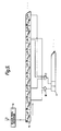
- the operation of the feature matching device is shown in Figures 4 and 5.
- the device comprises a long shift register (15) into which the pixels (4) from successive horizontal scan lines of the document are fed.
- the shift register (15) is arranged as shown in Figure 4 so that it in effect comprises a matrix which is several pixels deep (for example about 30) and as many pixels wide as the document (for example about 2000) (in Figures 4 and 5 only 10 lines of pixels are shown for simplicity).
- At one end of this matrix is a smaller matrix (16), slightly bigger than the size of the largest character to be recognised, to the cells of which are connected the inputs of the feature detectors (17, 18) only two of which are shown in Figure 4 for simplicity.
- the feature detectors may comprise for example AND logic elements.
- feature detectors each comprising from 1 to 12 inputs to a single matrix of feature detector cells (16) which is only for example 30x16 cells big. This is particularly so in custom built VLSI integrated circuit implementations of the system where the density of interconnects to each feature detector matrix cell is preferably kept low.
- the feature detectors may be connected to other cells in the shift register so that the same features are detected in a portion of data but at a time when the data has moved to a different portion of the shift register.
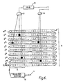
- time delay circuits (20) may be provided as shown in Figure 6 so that the features detected at various areas in the 30x2000 array would be fed to the decision circuit simultaneously as if from a set of detectors connected to a single 30x16 array portion (16) of the whole register (the portion (16) shown in Figures 5 and 6 is only 10x8 cells big for simplicity).
- the shift register thus contains a greater number of cells to which feature detectors are connected than would be required if the features were detected simultaneously without the delay circuits. As a result the density of feature detector connections per cell is lower than if the features were detected in a single 30x16 array without using the delay circuits.
- the binary outputs (6) from feature logics (17, 18) corresponding to each of the features are supplied to the label assignment decision circuit (7).
- the label assignment decision circuit (7) compares the outputs (6) simultaneously with a plurality of labelled binary reference vectors as the components of the reference vectors are read out in time parallel fashion from a plurality of registers. On completion of the comparisons the reference vector which most closely matches the binary feature response signal (6) is output together with a measure of confidence in this label.
- a suitable form of decision circuit which can be used is described in US patent 4119946. Use of such a form of decision circuit and feature detection enables extra features and extra reference vectors to be added to the system or existing ones to be extended quite easily without affecting the arrangement of existing hardware. This is particularly useful in extending the recognition capabilities of the system as new recognition problems are encountered. Due to the parallelism of the recognition process such extension does not necessarily slow down the recognition process which enables the system to work at video speeds even when subsequent hardware extensions are made.
- the label and confidence measure information (8) together with positional information (10) giving the location of the corresponding areas of the input pattern to which the labels have been assigned are passed to the syntactic processing device (9).
- the sequence of tasks performed by syntactic processing device (9) is shown diagrammatically in Figure 7.
- the essential task of the syntactic processing device is accomplished by the input of labels L, associated confidence measures d and corresponding positional information comprising X and Y coordinates which define the area of the input pattern to which the label L has been assigned.
- the relationship between the original text and the area values in the buffer is shown diagrammatically in simplified form in Figure 8.
- the buffer 29 is composed of an array of area values (30) each having label L confidence measure d (where d in this instance is inversely proportional to the amount of confidence in the assignment of label L) and positional information comprising X and Y coordinates.
- the corresponding area of original text (31) comprises a series of overlapping rectangular areas of text each having corresponding X and Y coordinates and each corresponding in pixel size to the size of the part of the shift register matrix (16) containing the feature detectors (in the embodiment shown in Fig. 4).
- the areas of text each differ in position from each other by one row of pixels in the binarised form of the text.
- the feature detectors effectively scan pixels corresponding to successive rows of areas and the decision means then feeds corresponding area values into the buffer.
- area values for position (3, 4) have just been entered and following that it will be decided that A is to be output for position (2, 3).
- a "3" will already have been output for position (7, 2).
- the inter character contiguities represented by for example positions (4, 3) and (4, 2) have been assigned the label "space" by the decision means.
- the buffer used is large enough to store area values for at least three overlapping scan lines of areas of the document being read. Once area values are no longer needed to make further tests for maxima they may be overwritten by new data. As shown in Figure 7 in addition to the decision process (21) about the position (X,Y), a number of other functions are performed by the syntactic processing device in this embodiment.
- syntactic processing steps which may be carried out are spelling checks and elimination of unlikely word adjacencies.
- the output of labels L at the end of syntactic processing is accompanied by the format controls for the output device to which they are fed which could be for example a word processor.
- the entire recognition system including the syntactic processing device and the 2 dimensional area value buffer and page character stores which carried out the steps and decisions shown in Figure 7 may be constructed using known electronic circuitry and preferably VLSI circuits. However, the device may be implemented using software.
- the entire system is particularly amenable to construction using VLSI which combined with the advantages the system has in the way it can operate continuously and without any preprocessing steps gives a pattern recognition system capable of working continuously at high speeds and in particular at video speeds which facilitates numerous applications of the system in addition to use of the system as an optical character page reader.
Landscapes
- Engineering & Computer Science (AREA)
- Computer Vision & Pattern Recognition (AREA)
- Theoretical Computer Science (AREA)
- Medical Informatics (AREA)
- Health & Medical Sciences (AREA)
- Databases & Information Systems (AREA)
- Evolutionary Computation (AREA)
- General Health & Medical Sciences (AREA)
- Artificial Intelligence (AREA)
- Software Systems (AREA)
- Computing Systems (AREA)
- Physics & Mathematics (AREA)
- General Physics & Mathematics (AREA)
- Multimedia (AREA)
- Character Discrimination (AREA)
- Character Input (AREA)
- Image Analysis (AREA)
- Image Processing (AREA)
- Holo Graphy (AREA)
Claims (15)
Priority Applications (1)
| Application Number | Priority Date | Filing Date | Title |
|---|---|---|---|
| AT85302060T ATE56549T1 (de) | 1984-04-10 | 1985-03-25 | Mustererkennungseinrichtung. |
Applications Claiming Priority (2)
| Application Number | Priority Date | Filing Date | Title |
|---|---|---|---|
| GB8409196 | 1984-04-10 | ||
| GB8409196 | 1984-04-10 |
Publications (2)
| Publication Number | Publication Date |
|---|---|
| EP0163377A1 EP0163377A1 (fr) | 1985-12-04 |
| EP0163377B1 true EP0163377B1 (fr) | 1990-09-12 |
Family
ID=10559444
Family Applications (1)
| Application Number | Title | Priority Date | Filing Date |
|---|---|---|---|
| EP85302060A Expired - Lifetime EP0163377B1 (fr) | 1984-04-10 | 1985-03-25 | Système de reconnaissance de formes |
Country Status (5)
| Country | Link |
|---|---|
| US (1) | US4817171A (fr) |
| EP (1) | EP0163377B1 (fr) |
| JP (2) | JPS615386A (fr) |
| AT (1) | ATE56549T1 (fr) |
| DE (1) | DE3579627D1 (fr) |
Families Citing this family (37)
| Publication number | Priority date | Publication date | Assignee | Title |
|---|---|---|---|---|
| GB8517918D0 (en) * | 1985-07-16 | 1985-08-21 | British Telecomm | Recognition system |
| US5109432A (en) * | 1989-12-27 | 1992-04-28 | Fujitsu Limited | Character recognition method |
| US5081690A (en) * | 1990-05-08 | 1992-01-14 | Eastman Kodak Company | Row-by-row segmentation and thresholding for optical character recognition |
| US5168147A (en) * | 1990-07-31 | 1992-12-01 | Xerox Corporation | Binary image processing for decoding self-clocking glyph shape codes |
| CA2044404C (fr) * | 1990-07-31 | 1998-06-23 | Dan S. Bloomberg | Codes en forme de glyphes a auto-synchronisation |
| USRE38758E1 (en) * | 1990-07-31 | 2005-07-19 | Xerox Corporation | Self-clocking glyph shape codes |
| US5091968A (en) * | 1990-12-28 | 1992-02-25 | Ncr Corporation | Optical character recognition system and method |
| US10361802B1 (en) | 1999-02-01 | 2019-07-23 | Blanding Hovenweep, Llc | Adaptive pattern recognition based control system and method |
| US5903454A (en) | 1991-12-23 | 1999-05-11 | Hoffberg; Linda Irene | Human-factored interface corporating adaptive pattern recognition based controller apparatus |
| US7242988B1 (en) | 1991-12-23 | 2007-07-10 | Linda Irene Hoffberg | Adaptive pattern recognition based controller apparatus and method and human-factored interface therefore |
| US6400996B1 (en) | 1999-02-01 | 2002-06-04 | Steven M. Hoffberg | Adaptive pattern recognition based control system and method |
| US6418424B1 (en) | 1991-12-23 | 2002-07-09 | Steven M. Hoffberg | Ergonomic man-machine interface incorporating adaptive pattern recognition based control system |
| US8352400B2 (en) | 1991-12-23 | 2013-01-08 | Hoffberg Steven M | Adaptive pattern recognition based controller apparatus and method and human-factored interface therefore |
| US6850252B1 (en) | 1999-10-05 | 2005-02-01 | Steven M. Hoffberg | Intelligent electronic appliance system and method |
| US5292127C1 (en) * | 1992-10-02 | 2001-05-22 | Arcade Planet Inc | Arcade game |
| US7721307B2 (en) | 1992-12-09 | 2010-05-18 | Comcast Ip Holdings I, Llc | Method and apparatus for targeting of interactive virtual objects |
| JP3108979B2 (ja) * | 1994-07-28 | 2000-11-13 | セイコーエプソン株式会社 | 画像処理方法および画像処理装置 |
| US5784485A (en) * | 1994-08-25 | 1998-07-21 | Xu; Youguang | Method and apparatus for automated pattern recognition |
| US5912700A (en) * | 1996-01-10 | 1999-06-15 | Fox Sports Productions, Inc. | System for enhancing the television presentation of an object at a sporting event |
| US6535681B2 (en) * | 2001-06-19 | 2003-03-18 | Lucent Technologies Inc. | Fiber-optic cable routing and bend limiting device and system |
| US5917553A (en) * | 1996-10-22 | 1999-06-29 | Fox Sports Productions Inc. | Method and apparatus for enhancing the broadcast of a live event |
| US5799148A (en) * | 1996-12-23 | 1998-08-25 | General Electric Company | System and method for estimating a measure of confidence in a match generated from a case-based reasoning system |
| US6252632B1 (en) | 1997-01-17 | 2001-06-26 | Fox Sports Productions, Inc. | System for enhancing a video presentation |
| US5953077A (en) * | 1997-01-17 | 1999-09-14 | Fox Sports Productions, Inc. | System for displaying an object that is not visible to a camera |
| US6266100B1 (en) | 1998-09-04 | 2001-07-24 | Sportvision, Inc. | System for enhancing a video presentation of a live event |
| US6229550B1 (en) | 1998-09-04 | 2001-05-08 | Sportvision, Inc. | Blending a graphic |
| US7966078B2 (en) | 1999-02-01 | 2011-06-21 | Steven Hoffberg | Network media appliance system and method |
| US7075556B1 (en) * | 1999-10-21 | 2006-07-11 | Sportvision, Inc. | Telestrator system |
| US6909438B1 (en) | 2000-02-04 | 2005-06-21 | Sportvision, Inc. | Video compositor |
| US7145556B2 (en) * | 2001-10-29 | 2006-12-05 | Anoto Ab | Method and device for decoding a position-coding pattern |
| SE0103589L (sv) * | 2001-10-29 | 2003-04-30 | Anoto Ab | Förfarande och anordning för avkodning av ett positionskodningsmönster |
| US7487148B2 (en) * | 2003-02-28 | 2009-02-03 | Eaton Corporation | System and method for analyzing data |
| WO2004097723A1 (fr) * | 2003-04-29 | 2004-11-11 | Anoto Ip Lic Hb | Procedes, appareil, programme d'ordinateur et support d'enregistrement destine au decodage de position |
| US8073256B2 (en) * | 2007-11-15 | 2011-12-06 | Canon Kabushiki Kaisha | Image processing apparatus and method therefor |
| JP5340088B2 (ja) * | 2009-09-07 | 2013-11-13 | キヤノン株式会社 | 情報処理方法及び装置 |
| US9215383B2 (en) | 2011-08-05 | 2015-12-15 | Sportsvision, Inc. | System for enhancing video from a mobile camera |
| US11956400B2 (en) | 2022-08-30 | 2024-04-09 | Capital One Services, Llc | Systems and methods for measuring document legibility |
Family Cites Families (13)
| Publication number | Priority date | Publication date | Assignee | Title |
|---|---|---|---|---|
| US3303466A (en) * | 1963-03-05 | 1967-02-07 | Control Data Corp | Character separating reading machine |
| US3519990A (en) * | 1966-09-15 | 1970-07-07 | Control Data Corp | Recognition system for reading machine |
| GB1270013A (en) * | 1968-07-18 | 1972-04-12 | Plessey Co Ltd | Improvements in or relating to optical character recognition systems |
| US3717848A (en) * | 1970-06-02 | 1973-02-20 | Recognition Equipment Inc | Stored reference code character reader method and system |
| JPS518699B1 (fr) * | 1970-11-09 | 1976-03-19 | ||
| JPS4966034A (fr) * | 1972-10-27 | 1974-06-26 | ||
| JPS5517988B2 (fr) * | 1974-06-05 | 1980-05-15 | ||
| GB1545117A (en) * | 1976-05-25 | 1979-05-02 | Nat Res Dev | Comparison apparatus eg for use in character recognition |
| JPS5313840A (en) * | 1976-07-23 | 1978-02-07 | Hitachi Ltd | Analogy calculator |
| US4110737A (en) * | 1977-08-22 | 1978-08-29 | The Singer Company | Character recognition apparatus for serially comparing an unknown character with a plurality of reference characters |
| JPS56110191A (en) * | 1980-02-05 | 1981-09-01 | Tokyo Keiki Co Ltd | Type character recognizing device |
| JPS57206989A (en) * | 1981-06-15 | 1982-12-18 | Toshiba Corp | Optical character reader |
| JPS59154575A (ja) * | 1983-02-23 | 1984-09-03 | Hitachi Ltd | 文字の認識方法 |
-
1985
- 1985-03-25 DE DE8585302060T patent/DE3579627D1/de not_active Expired - Lifetime
- 1985-03-25 EP EP85302060A patent/EP0163377B1/fr not_active Expired - Lifetime
- 1985-03-25 AT AT85302060T patent/ATE56549T1/de not_active IP Right Cessation
- 1985-04-09 US US06/721,402 patent/US4817171A/en not_active Expired - Lifetime
- 1985-04-10 JP JP60074587A patent/JPS615386A/ja active Pending
-
1992
- 1992-04-10 JP JP4118065A patent/JPH0757051A/ja active Pending
Also Published As
| Publication number | Publication date |
|---|---|
| ATE56549T1 (de) | 1990-09-15 |
| EP0163377A1 (fr) | 1985-12-04 |
| DE3579627D1 (de) | 1990-10-18 |
| JPS615386A (ja) | 1986-01-11 |
| JPH0757051A (ja) | 1995-03-03 |
| US4817171A (en) | 1989-03-28 |
Similar Documents
| Publication | Publication Date | Title |
|---|---|---|
| US4817171A (en) | Pattern recognition system | |
| KR100324847B1 (ko) | 수신인명 리드장치와 우편물등 구분기 및 문자열 인식방법 | |
| US4989258A (en) | Character recognition apparatus | |
| US5410611A (en) | Method for identifying word bounding boxes in text | |
| US5033104A (en) | Method for detecting character strings | |
| EP0516316A2 (fr) | Agent de sélection pour un système de détermination de symboles avec une pluralité de processeurs de reconnaissance de caractères | |
| US5590220A (en) | Bending point extraction method for optical character recognition system | |
| US5394484A (en) | Image recognition apparatus | |
| US4075605A (en) | Character recognition unit | |
| US5621818A (en) | Document recognition apparatus | |
| US5150425A (en) | Character recognition method using correlation search | |
| EP0551403B1 (fr) | Appareil et procedes de reconnaissance de caracteres pour la localisation et l'extraction de donnees predeterminees d'un document | |
| US4769849A (en) | Method and apparatus for separating overlapping patterns | |
| US5596657A (en) | Method of sorting out candidate characters in character recognition system | |
| US5721790A (en) | Methods and apparatus for separating integer and fractional portions of a financial amount | |
| US11710331B2 (en) | Systems and methods for separating ligature characters in digitized document images | |
| Koga et al. | Segmentation of Japanese handwritten characters using peripheral feature analysis | |
| KR100332752B1 (ko) | 문자인식방법 | |
| Graf et al. | Analysis of complex and noisy check images | |
| JP3428504B2 (ja) | 文字認識装置 | |
| CN119888768A (zh) | 一种图像识别的档案管理方法、系统以及电子设备 | |
| JPH03219384A (ja) | 文字認識装置 | |
| JPH11312219A (ja) | 宛名読取り装置および郵便物等区分機および文字列認識方法 | |
| JPH04373090A (ja) | 文字認識装置 | |
| Rosenfeld et al. | High-speed pattern recognition system |
Legal Events
| Date | Code | Title | Description |
|---|---|---|---|
| PUAI | Public reference made under article 153(3) epc to a published international application that has entered the european phase |
Free format text: ORIGINAL CODE: 0009012 |
|
| AK | Designated contracting states |
Designated state(s): AT BE CH DE FR GB IT LI LU NL SE |
|
| 17P | Request for examination filed |
Effective date: 19860528 |
|
| 17Q | First examination report despatched |
Effective date: 19881027 |
|
| RAP3 | Party data changed (applicant data changed or rights of an application transferred) |
Owner name: BRITISH TELECOMMUNICATIONS PUBLIC LIMITED COMPANY |
|
| GRAA | (expected) grant |
Free format text: ORIGINAL CODE: 0009210 |
|
| AK | Designated contracting states |
Kind code of ref document: B1 Designated state(s): AT BE CH DE FR GB IT LI LU NL SE |
|
| PG25 | Lapsed in a contracting state [announced via postgrant information from national office to epo] |
Ref country code: SE Effective date: 19900912 Ref country code: NL Effective date: 19900912 Ref country code: LI Effective date: 19900912 Ref country code: IT Free format text: LAPSE BECAUSE OF FAILURE TO SUBMIT A TRANSLATION OF THE DESCRIPTION OR TO PAY THE FEE WITHIN THE PRESCRIBED TIME-LIMIT;WARNING: LAPSES OF ITALIAN PATENTS WITH EFFECTIVE DATE BEFORE 2007 MAY HAVE OCCURRED AT ANY TIME BEFORE 2007. THE CORRECT EFFECTIVE DATE MAY BE DIFFERENT FROM THE ONE RECORDED. Effective date: 19900912 Ref country code: FR Effective date: 19900912 Ref country code: CH Effective date: 19900912 Ref country code: BE Effective date: 19900912 Ref country code: AT Effective date: 19900912 |
|
| REF | Corresponds to: |
Ref document number: 56549 Country of ref document: AT Date of ref document: 19900915 Kind code of ref document: T |
|
| REF | Corresponds to: |
Ref document number: 3579627 Country of ref document: DE Date of ref document: 19901018 |
|
| REG | Reference to a national code |
Ref country code: CH Ref legal event code: PL |
|
| EN | Fr: translation not filed | ||
| NLV1 | Nl: lapsed or annulled due to failure to fulfill the requirements of art. 29p and 29m of the patents act | ||
| PG25 | Lapsed in a contracting state [announced via postgrant information from national office to epo] |
Ref country code: GB Effective date: 19910325 |
|
| PG25 | Lapsed in a contracting state [announced via postgrant information from national office to epo] |
Ref country code: LU Free format text: LAPSE BECAUSE OF NON-PAYMENT OF DUE FEES Effective date: 19910331 |
|
| PLBE | No opposition filed within time limit |
Free format text: ORIGINAL CODE: 0009261 |
|
| STAA | Information on the status of an ep patent application or granted ep patent |
Free format text: STATUS: NO OPPOSITION FILED WITHIN TIME LIMIT |
|
| 26N | No opposition filed | ||
| GBPC | Gb: european patent ceased through non-payment of renewal fee | ||
| PG25 | Lapsed in a contracting state [announced via postgrant information from national office to epo] |
Ref country code: DE Effective date: 19920101 |