EP0163396B1 - Elektromagnetischer Durchflussmesser vom Restmagnetismustyp - Google Patents
Elektromagnetischer Durchflussmesser vom Restmagnetismustyp Download PDFInfo
- Publication number
- EP0163396B1 EP0163396B1 EP85302600A EP85302600A EP0163396B1 EP 0163396 B1 EP0163396 B1 EP 0163396B1 EP 85302600 A EP85302600 A EP 85302600A EP 85302600 A EP85302600 A EP 85302600A EP 0163396 B1 EP0163396 B1 EP 0163396B1
- Authority
- EP
- European Patent Office
- Prior art keywords
- magnetic
- portions
- retentivity
- residual magnetism
- electromagnetic flowmeter
- Prior art date
- Legal status (The legal status is an assumption and is not a legal conclusion. Google has not performed a legal analysis and makes no representation as to the accuracy of the status listed.)
- Expired
Links
- 230000005389 magnetism Effects 0.000 title claims description 22
- 230000004907 flux Effects 0.000 claims description 58
- 238000005070 sampling Methods 0.000 claims description 17
- 239000012530 fluid Substances 0.000 claims description 13
- 230000005284 excitation Effects 0.000 claims description 12
- 230000005415 magnetization Effects 0.000 claims description 6
- 230000000977 initiatory effect Effects 0.000 claims description 5
- 239000012811 non-conductive material Substances 0.000 claims description 4
- 239000000696 magnetic material Substances 0.000 claims 3
- 238000010586 diagram Methods 0.000 description 13
- 230000007423 decrease Effects 0.000 description 5
- 230000007547 defect Effects 0.000 description 3
- 238000005259 measurement Methods 0.000 description 3
- 239000007787 solid Substances 0.000 description 3
- 239000000463 material Substances 0.000 description 2
- 239000007779 soft material Substances 0.000 description 2
- 229910000831 Steel Inorganic materials 0.000 description 1
- 230000032683 aging Effects 0.000 description 1
- 230000002238 attenuated effect Effects 0.000 description 1
- 230000001419 dependent effect Effects 0.000 description 1
- 230000010354 integration Effects 0.000 description 1
- 238000004519 manufacturing process Methods 0.000 description 1
- 238000012986 modification Methods 0.000 description 1
- 230000004048 modification Effects 0.000 description 1
- 230000004043 responsiveness Effects 0.000 description 1
- 239000010959 steel Substances 0.000 description 1
Images




Classifications
-
- G—PHYSICS
- G01—MEASURING; TESTING
- G01F—MEASURING VOLUME, VOLUME FLOW, MASS FLOW OR LIQUID LEVEL; METERING BY VOLUME
- G01F1/00—Measuring the volume flow or mass flow of fluid or fluent solid material wherein the fluid passes through a meter in a continuous flow
- G01F1/56—Measuring the volume flow or mass flow of fluid or fluent solid material wherein the fluid passes through a meter in a continuous flow by using electric or magnetic effects
- G01F1/58—Measuring the volume flow or mass flow of fluid or fluent solid material wherein the fluid passes through a meter in a continuous flow by using electric or magnetic effects by electromagnetic flowmeters
- G01F1/586—Measuring the volume flow or mass flow of fluid or fluent solid material wherein the fluid passes through a meter in a continuous flow by using electric or magnetic effects by electromagnetic flowmeters constructions of coils, magnetic circuits, accessories therefor
Definitions
- Fig. 1 is a diagram showing the connection thereof (reference is made to Japanese Patent Publication No. 59-007930 and U.S. Patent 4,409,846).
- the magnetic circuit includes retentivity portions 4ao and 4bo disposed parallelly with each other but each connected serially with the magnetic flux gap 3co.
- the retentivity portions 4ao and 4bo are made of a magnetically hard orsemihard material identically with each other such that residual magnetism remains at the retentivity portions 4ao and 4bo after a magnetic field exerted to these portions to magnetize them has been removed therefrom.
- the other portions of the magnetic circuit are made of a magnetically soft material.
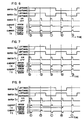
- the control circuit 7o produces a sampling pulse signal Spo having a predetermined sampling duration Ts which has been set to occur in a predetermined period of time after the end of every intermittently flowing current and before the initiation of the next conduction of the intermittently flowing current, as shown in Fig. 2.
- a flow rate calculating means 10 0 receives.
- the AC type noise component e 2 or e 2 ' is caused by the sharp increase or decrease in the magnetic flux (0 0 and includes a portion gradually attenuated until the occurrence of the next sharp increase or decrease in the magnetic flux.
- the sampled voltage Vso may include not only the DC type noise component e 1 but also the AC type noise component e 2 or e 2 ' in addition to the signal component proportional to the flow rate, even if the timing of the sampling pulse Spo is set at a point of time immediately before the next current conduction, as shown in the waveform Vso in Fig. 2.
- Fig. 11 shows another embodiment which is arranged similarly to the Fig. 4 embodiment except that an upper half portion and a lower half portion of a single bar-like retentivity portion 4 as shown in the drawing are used as a series connected of two retentivity portions 4a and 4b, and which operates in the same manner as the Fig. 4 embodiment.
Landscapes
- Physics & Mathematics (AREA)
- Engineering & Computer Science (AREA)
- Power Engineering (AREA)
- Electromagnetism (AREA)
- Fluid Mechanics (AREA)
- General Physics & Mathematics (AREA)
- Measuring Volume Flow (AREA)
Claims (8)
Applications Claiming Priority (2)
| Application Number | Priority Date | Filing Date | Title |
|---|---|---|---|
| JP59098207A JPS60242318A (ja) | 1984-05-16 | 1984-05-16 | 残留磁気式電磁流量計 |
| JP98207/84 | 1984-05-16 |
Publications (2)
| Publication Number | Publication Date |
|---|---|
| EP0163396A1 EP0163396A1 (de) | 1985-12-04 |
| EP0163396B1 true EP0163396B1 (de) | 1989-07-05 |
Family
ID=14213538
Family Applications (1)
| Application Number | Title | Priority Date | Filing Date |
|---|---|---|---|
| EP85302600A Expired EP0163396B1 (de) | 1984-05-16 | 1985-04-15 | Elektromagnetischer Durchflussmesser vom Restmagnetismustyp |
Country Status (4)
| Country | Link |
|---|---|
| US (1) | US4601209A (de) |
| EP (1) | EP0163396B1 (de) |
| JP (1) | JPS60242318A (de) |
| DE (1) | DE3571351D1 (de) |
Families Citing this family (30)
| Publication number | Priority date | Publication date | Assignee | Title |
|---|---|---|---|---|
| DE3530055A1 (de) * | 1985-08-22 | 1987-03-05 | Thurau Klaus | Elektromagnetischer flussmesser |
| US4736634A (en) * | 1985-12-27 | 1988-04-12 | Aichi Tokei Denki Co., Ltd. | Magnetic field generating device for electromagnetic flowmeter of residual magnetization type |
| JPH0713584B2 (ja) * | 1986-01-31 | 1995-02-15 | 愛知時計電機株式会社 | 残留磁気型電磁流量計を用いた熱量計 |
| JP2751152B2 (ja) * | 1986-09-27 | 1998-05-18 | 株式会社島津製作所 | 電磁流量計 |
| US4727755A (en) * | 1986-12-08 | 1988-03-01 | Fischer & Porter Co. | Electromagnetic flowmeter with alternating permanent magnet field |
| DE4119372A1 (de) * | 1991-06-12 | 1992-12-17 | Fischer & Porter Gmbh | Schaltungsanordnung fuer eine vorrichtung zur messung des volumenstroms eines ein rohr durchfliessenden mediums |
| US5289725A (en) * | 1991-07-31 | 1994-03-01 | The Foxboro Company | Monolithic flow tube with improved dielectric properties for use with a magnetic flowmeter |
| EP0596153A1 (de) * | 1992-11-06 | 1994-05-11 | TURBO-WERK Messtechnik GmbH | Induktiver Durchflussmesser |
| US6085599A (en) * | 1995-04-26 | 2000-07-11 | Feller; Murray F. | Magnetic flow sensor |
| GB2324606B (en) * | 1997-04-25 | 2002-01-16 | Kent Meters Ltd | Electromagnetic flowmeter |
| US6380787B1 (en) * | 1999-08-31 | 2002-04-30 | Micron Technology, Inc. | Integrated circuit and method for minimizing clock skews |
| DE10317456B4 (de) * | 2003-04-16 | 2005-09-29 | Siemens Flow Instruments A/S | Verfahren zum Betreiben eines magnetisch-induktiven Durchflußmessers |
| US20060238284A1 (en) * | 2005-03-30 | 2006-10-26 | Dimig Steven J | Residual magnetic devices and methods |
| US20060219499A1 (en) * | 2005-03-30 | 2006-10-05 | Organek Gregory J | Residual magnetic devices and methods |
| US20060237959A1 (en) * | 2005-03-30 | 2006-10-26 | Dimig Steven J | Residual magnetic devices and methods |
| US20060238285A1 (en) * | 2005-03-30 | 2006-10-26 | Dimig Steven J | Residual magnetic devices and methods |
| US20060219497A1 (en) * | 2005-03-30 | 2006-10-05 | Organek Gregory J | Residual magnetic devices and methods |
| US8403124B2 (en) | 2005-03-30 | 2013-03-26 | Strattec Security Corporation | Residual magnetic devices and methods |
| US7969705B2 (en) * | 2005-03-30 | 2011-06-28 | Strattec Security Corporation | Residual magnetic devices and methods |
| US20060219498A1 (en) * | 2005-03-30 | 2006-10-05 | Organek Gregory J | Residual magnetic devices and methods |
| US20060226941A1 (en) * | 2005-03-30 | 2006-10-12 | Dimig Steven J | Residual magnetic devices and methods |
| US7401483B2 (en) * | 2005-03-30 | 2008-07-22 | Strattec Security Corporation | Residual magnetic devices and methods for an ignition actuation blockage device |
| US20060219496A1 (en) * | 2005-03-30 | 2006-10-05 | Dimig Steven J | Residual magnetic devices and methods |
| US20060219513A1 (en) * | 2005-03-30 | 2006-10-05 | Organek Gregory J | Residual magnetic devices and methods |
| US20060226942A1 (en) * | 2005-03-30 | 2006-10-12 | Dimig Steven J | Residual magnetic devices and methods |
| JP5163852B2 (ja) * | 2007-03-13 | 2013-03-13 | 横河電機株式会社 | 電磁流量計とそのゼロ点測定方法 |
| JP5973775B2 (ja) | 2012-04-27 | 2016-08-23 | 株式会社東芝 | 電磁流量計、その励磁回路部の自己診断方法 |
| JP2016142648A (ja) * | 2015-02-03 | 2016-08-08 | アズビル株式会社 | 電磁流量計および励磁制御方法 |
| JP5877259B1 (ja) * | 2015-04-24 | 2016-03-02 | 東京計装株式会社 | 電磁流量計の信号抽出方法 |
| DE102022115271B3 (de) * | 2022-06-20 | 2023-11-02 | Krohne Messtechnik Gmbh | Magnetfeldgenerator für ein magnetisch-induktives Durchflussmessgerät, Verfahren zum Betreiben eines solchen, magnetisch-induktives Durchflussmessgerät und Verfahren zum Betreiben eines solchen |
Family Cites Families (4)
| Publication number | Priority date | Publication date | Assignee | Title |
|---|---|---|---|---|
| DE2454469C3 (de) * | 1974-11-16 | 1981-07-23 | Fischer & Porter GmbH, 3400 Göttingen | Induktiver Durchflußmesser |
| DE2744845C3 (de) * | 1977-10-05 | 1985-08-08 | Flowtec AG, Reinach, Basel | Verfahren zur Kompensation der elektrochemischen Störgleichspannung bei der magnetisch-induktiven Durchflußmessung mit periodisch umgepoltem magnetischem Gleichfeld |
| US4409846A (en) * | 1979-02-08 | 1983-10-18 | Aichi Tokei Denki Co., Ltd. | Electromagnetic flow meter |
| JPS5927566B2 (ja) * | 1980-07-02 | 1984-07-06 | 日本光電工業株式会社 | 電磁血流計 |
-
1984
- 1984-05-16 JP JP59098207A patent/JPS60242318A/ja active Granted
-
1985
- 1985-04-12 US US06/722,537 patent/US4601209A/en not_active Expired - Fee Related
- 1985-04-15 DE DE8585302600T patent/DE3571351D1/de not_active Expired
- 1985-04-15 EP EP85302600A patent/EP0163396B1/de not_active Expired
Also Published As
| Publication number | Publication date |
|---|---|
| DE3571351D1 (en) | 1989-08-10 |
| JPS60242318A (ja) | 1985-12-02 |
| EP0163396A1 (de) | 1985-12-04 |
| JPH0377933B2 (de) | 1991-12-12 |
| US4601209A (en) | 1986-07-22 |
Similar Documents
| Publication | Publication Date | Title |
|---|---|---|
| US4601209A (en) | Electromagnetic flowmeter of the residual magnetism type | |
| US4409846A (en) | Electromagnetic flow meter | |
| JP2923307B2 (ja) | 電流センサ | |
| US2849614A (en) | Electrical inverter circuits | |
| EP0294924B1 (de) | Verfahren und Vorrichtung zum Kompensieren der Offset-Gleichspannung in einem elektromagnetischen Durchflussmesser | |
| US3699442A (en) | Bi-directional signal detector with input/output isolation | |
| GB2081449A (en) | Electromagnetic flow meters | |
| US4278938A (en) | Electromagnetic arrangement for measuring electrical current | |
| JP3899225B2 (ja) | 磁気誘導式流量測定方法 | |
| US5641914A (en) | Inductive flow meter | |
| US4766770A (en) | Low duty cycle electromagnetic flowmeter | |
| US4727755A (en) | Electromagnetic flowmeter with alternating permanent magnet field | |
| JP2021170041A (ja) | 電流センサ | |
| CA2071296C (en) | Fluid flowrate measuring apparatus | |
| US4597295A (en) | Electromagnetic flowmeter | |
| CN100363719C (zh) | 电磁流量计 | |
| JPH06118111A (ja) | 漏電検出装置 | |
| EP0990919A2 (de) | Steuerschaltung für ein Magnetoimpedanzelement | |
| US3328689A (en) | A.c. amplified hall generator wattmeter | |
| US5400660A (en) | Inductive flow meter | |
| SU1150564A1 (ru) | Суммирующий измерительный преобразователь электрических сигналов с гальваническим разделением между цеп ми | |
| JPH0134090Y2 (de) | ||
| JPS5451562A (en) | Calibration method of electromagnetic flow meter | |
| JPH0470518A (ja) | 電磁流量計 | |
| US3004204A (en) | Carrier type amplifier |
Legal Events
| Date | Code | Title | Description |
|---|---|---|---|
| PUAI | Public reference made under article 153(3) epc to a published international application that has entered the european phase |
Free format text: ORIGINAL CODE: 0009012 |
|
| AK | Designated contracting states |
Designated state(s): DE FR GB |
|
| 17P | Request for examination filed |
Effective date: 19860515 |
|
| 17Q | First examination report despatched |
Effective date: 19870923 |
|
| GRAA | (expected) grant |
Free format text: ORIGINAL CODE: 0009210 |
|
| AK | Designated contracting states |
Kind code of ref document: B1 Designated state(s): DE FR GB |
|
| REF | Corresponds to: |
Ref document number: 3571351 Country of ref document: DE Date of ref document: 19890810 |
|
| ET | Fr: translation filed | ||
| PLBE | No opposition filed within time limit |
Free format text: ORIGINAL CODE: 0009261 |
|
| STAA | Information on the status of an ep patent application or granted ep patent |
Free format text: STATUS: NO OPPOSITION FILED WITHIN TIME LIMIT |
|
| 26N | No opposition filed | ||
| PGFP | Annual fee paid to national office [announced via postgrant information from national office to epo] |
Ref country code: DE Payment date: 19960403 Year of fee payment: 12 |
|
| PGFP | Annual fee paid to national office [announced via postgrant information from national office to epo] |
Ref country code: GB Payment date: 19960409 Year of fee payment: 12 |
|
| PGFP | Annual fee paid to national office [announced via postgrant information from national office to epo] |
Ref country code: FR Payment date: 19960424 Year of fee payment: 12 |
|
| PG25 | Lapsed in a contracting state [announced via postgrant information from national office to epo] |
Ref country code: GB Effective date: 19970415 |
|
| GBPC | Gb: european patent ceased through non-payment of renewal fee |
Effective date: 19970415 |
|
| PG25 | Lapsed in a contracting state [announced via postgrant information from national office to epo] |
Ref country code: FR Free format text: LAPSE BECAUSE OF NON-PAYMENT OF DUE FEES Effective date: 19971231 |
|
| PG25 | Lapsed in a contracting state [announced via postgrant information from national office to epo] |
Ref country code: DE Free format text: LAPSE BECAUSE OF NON-PAYMENT OF DUE FEES Effective date: 19980101 |
|
| REG | Reference to a national code |
Ref country code: FR Ref legal event code: ST |