EP0163487A2 - Véhicule tout terrain - Google Patents
Véhicule tout terrain Download PDFInfo
- Publication number
- EP0163487A2 EP0163487A2 EP85303621A EP85303621A EP0163487A2 EP 0163487 A2 EP0163487 A2 EP 0163487A2 EP 85303621 A EP85303621 A EP 85303621A EP 85303621 A EP85303621 A EP 85303621A EP 0163487 A2 EP0163487 A2 EP 0163487A2
- Authority
- EP
- European Patent Office
- Prior art keywords
- wheel
- cross
- articulation means
- centre
- universal articulation
- Prior art date
- Legal status (The legal status is an assumption and is not a legal conclusion. Google has not performed a legal analysis and makes no representation as to the accuracy of the status listed.)
- Withdrawn
Links
- 238000010276 construction Methods 0.000 claims description 3
- 230000035939 shock Effects 0.000 description 4
- 230000001788 irregular Effects 0.000 description 3
- 230000000717 retained effect Effects 0.000 description 2
- 239000000725 suspension Substances 0.000 description 2
- 238000005452 bending Methods 0.000 description 1
- 230000008094 contradictory effect Effects 0.000 description 1
- 230000001747 exhibiting effect Effects 0.000 description 1
- 239000012530 fluid Substances 0.000 description 1
- 230000004048 modification Effects 0.000 description 1
- 238000012986 modification Methods 0.000 description 1
- 239000012858 resilient material Substances 0.000 description 1
Images

Classifications
-
- B—PERFORMING OPERATIONS; TRANSPORTING
- B62—LAND VEHICLES FOR TRAVELLING OTHERWISE THAN ON RAILS
- B62D—MOTOR VEHICLES; TRAILERS
- B62D61/00—Motor vehicles or trailers, characterised by the arrangement or number of wheels, not otherwise provided for, e.g. four wheels in diamond pattern
- B62D61/10—Motor vehicles or trailers, characterised by the arrangement or number of wheels, not otherwise provided for, e.g. four wheels in diamond pattern with more than four wheels
-
- B—PERFORMING OPERATIONS; TRANSPORTING
- B60—VEHICLES IN GENERAL
- B60G—VEHICLE SUSPENSION ARRANGEMENTS
- B60G5/00—Resilient suspensions for a set of tandem wheels or axles having interrelated movements
- B60G5/01—Resilient suspensions for a set of tandem wheels or axles having interrelated movements the set being characterised by having more than two successive axles
-
- B—PERFORMING OPERATIONS; TRANSPORTING
- B60—VEHICLES IN GENERAL
- B60K—ARRANGEMENT OR MOUNTING OF PROPULSION UNITS OR OF TRANSMISSIONS IN VEHICLES; ARRANGEMENT OR MOUNTING OF PLURAL DIVERSE PRIME-MOVERS IN VEHICLES; AUXILIARY DRIVES FOR VEHICLES; INSTRUMENTATION OR DASHBOARDS FOR VEHICLES; ARRANGEMENTS IN CONNECTION WITH COOLING, AIR INTAKE, GAS EXHAUST OR FUEL SUPPLY OF PROPULSION UNITS IN VEHICLES
- B60K17/00—Arrangement or mounting of transmissions in vehicles
- B60K17/36—Arrangement or mounting of transmissions in vehicles for driving tandem wheels
Definitions
- This invention relates to a cross-country vehicle, that is to a vehicle for travelling across rough terrain such as in forests.
- a known cross-country vehicle is disclosed in West German Offenlegungsschrift 2,437,476.' Such a known cross-country vehicle has a centre beam and on each of the longitudinal sides of the centre beam is a respective wheel beam, each wheel beam having at least three driven wheels and each wheel beam being universally articulated to the centre beam via a ball-and-socket joint.
- each wheel beam is mutually articulately connected to the centre beam by a guide rod which is arranged immediately below the ball-and-socket joint in the vertical direction and the wheel beams are further connected mutually and to the centre beam at the vehicle front end via a guide rod arrangement, so that when a wheel beam is pivoted about the ball-and-socket joint in one direction the other wheel beam is rotated about its ball-and-socket joint in the opposite direction.
- the disclosed guide rod arrangement consists of two wishbones, each forming a right-angled triangle, which are articulated by the apex enclosing the right angle to the centre beam at a first articulation point and are likewise connected articulately to the centre beam via a pendulum stanchion at a second articulation point located vertically below the first articulation point.
- the third externally located apex of each wishbone is attached articulately to a wheel beam.
- This known cross-country vehicle is relatively complicated as regards the suspension of the wheel beams on the centre beam.
- the known cross-country vehicle also exhibits, inter alia, the disadvantage that, due to the arrangement of the guide rod immediately below the ball-and-socket joint, this guide rod is unable, or not optimally able, to absorb shocks which, for example, are exerted laterally upon the rear end of one of the two wheel beams, when travelling across country.
- the object of this invention is to provide a cross-country vehicle which exhibits a particularly simple construction as regards the suspension of the wheel beams on the centre beam.
- a cross-country vehicle having a centre beam and two parallel and equi-spaced wheel beams located on each side of a longitudinal axis of the centre beam, each wheel beam having at least three longitudinally spaced driven wheels, a universal articulation means arranged to connect each wheel beam to the centre beam, the universal articulation means having a comnon axis oriented transversely to the longitudinal axis, and a guide rod arrangement connecting a forward end of each wheel beam to the centre beam, characterised in that the guide rod arrangement is provided at both forward and rearward ends of each wheel beam, and in that each guide rod arrangement comprises a pair of guide rods, one end of each guide rod being connected to a respective wheel beam by first universal articulation means with the other end thereof being connected to the centre beam by a second universal articulation means, the location of the second universal articulation means being on the opposite side of the axis from the first universal articulation means and both the first and second universal articulation means being located below the universal articulation
- the individual guide rods are preferably articulated to the wheel beams or to the centre beam respectively via ball-and-socket joints or articulations acting in ball-and-socket fashion, or else via cardan-tyge joints.
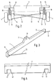
- the cross-country vehicle shown in the figures has two parallel wheel beams 1 and 2 each equi-spaced about a longitudinal median axis M and disposed on a respective longitudinal side of a centre beam 7.
- Each wheel beam 1, 2 is formed by an elongate girder-like and box-like element which is increased in height at a median portion 3.
- the wheel beams 1, 2 are located with their longitudinal extent in the longitudinal direction of the vehicle, indicated by arrow-headed line A.
- Each wheel beam 1 and 2 serves for the unsprung mounting of four driven wheels 4 which are provided on the outer longitudinal sides of the wheel beams and the wheels are equipped, for example, with low-pressure tyres exhibiting a degree of self-springing.
- Each wheel beam 1 and 2 is universally articulated in its median portion 3 by an articulation 6 to a respective longitudinal side of the centre beam 7 and the two articulations 6 are arranged on a common axis G oriented transversely or perpendicularly to the longitudinal direction of the vehicle (arrow-headed line A) and/or to the median axis M of the vehicle.
- Each articulation 6 is either a ball-and-socket joint or an articulation acting in a ball-and-socket fashion, that is to say, an articulation which permit pivotal movement of the wheel beams 1 and 2 not only about the horizontal axis G, but also about an axis parallel to the vehicle longitudinal axis M and about a further vertical axis likewise oriented perpendicularly to the axis G.
- Articulations acting in ball-and-socket fashion are, for example, such articulations that have a bolt attached to the centre beam 7, which bolt is encased by a joint sleeve which is in turn enccnpassed by a bush of resilient material, for example rubber, the bush being retained on a bracket to the appropriate wheel beam 1 or 2.
- the hydraulic connections with the hydraulic motors 5, at least in the transitional region between the centre beam 7 and the wheel beams 1 and 2, are made via flexible hoses. In order to keep the movement of the hydraulic motors 5 as small as possible during rotation or pivoting of the wheel beams 1 and 2 about the articulations 6, the hydraulic motors 5 are retained on the wheel beams 1 and 2 in immediate proximity of the articulations 6.
- Each wheel beam 1 and 2 is connected to the centre beam 7 via two bar-shaped guide rods 11 and 12 constructed as pendulum stanchions.
- the guide rod 11 is provided at the front end of the relevant wheel beam 1 or 2
- the guide rod 12 is located at the rear end of the relevant wheel beam 1 or 2.
- the opposite ends of each guide rod 11 and 12 are both universally articulated by means of a ball-and-socket joint or an articulation acting in ball-and-socket fashion; one end articulation 13 is connected to an appropriate wheel beam 1 or 2, and the opposite end articulation 14 is connected to the centre beam 7. As particularly shown in Figs.
- the articulations 13 are arranged on the wheel beams 1 and 2 so that they are located below the respective articulation 6 and are approximately equi-spaced thereabout in the longitudinal direction at opposing ends of the wheel beams 1 and 2.
- the articulations 6 and 13 on each wheel beam therefore form an isosceles triangle in a vertical plane.
- the two guide rods 11 and 12 provided respectively at the front end and at the rear end of the vehicle are oriented obliquely upwards towards the centre of the vehicle, starting from the articulation point 13, when the two wheel beams 1 and 2 are not rotated relative to the centre beam 7; that is to say, the wheel beams 1 and 2 and also the centre beam 7 are located with their respective longitudinal extent in a horizontal plane.
- the articulation points 14 for the guide rods 11 and 12 are arranged so that the two guide rods 11 and 12 provided at the front end and at the rear end of the vehicle, respectively, cross or overlap each other.
- the articulation 14 for the guide rod 12, the other end of which is articulated to the wheel beam 1, is located on that longitudinal side of the centre beam 7 which is adjacent to the wheel beam 2, that is to say closer to the wheel beam 2 than to the wheel beam 1.
- the articulation 14 for the guide rod 12, the 'other end of which is articulated to the wheel beam 2 is located closer to the wheel beam 1 than to the wheel beam 2.
- the articulations 14 for the two guide rods 11 are also arranged on the centre beam 7 at the front end of the vehicle in the same manner. The two wheel beams 1 and 2 are thus secured against tilting about the horizontal and vertical axis by the guide rods 11 and 12, in spite of the use of the articulations 6.
- the centre beam 7 has a frame part 15 which is provided on each of the two longitudinal sides of the centre beam 7 which is spaced above the wheel beams 1 and 2 and is braced against the ends of the wheel beams 1 and 2 respectively via four springs 16.
- the articulation of the two wheel beams 1 and 2 to the centre beam 7 by means of the articulations 6 and the guide rods 11 and 12 constructed as pendulum stanchions has the advantage that shocks which are exerted upon the ends of the wheel beams 1 and 2 laterally or in the direction transverse to the longitudinal direction of the vehicle, when travelling over irregular terrain for exanple, cannot become operative as bending moments in the articulations 6, but are transmitted directly to the centre beam 7 by the guide rods 11 and 12 provided at the ends of the two wheel beams 1 and 2.
- the elements used for articulating the wheel beams 1 and 2 are therefore subject only to mininum loading even in the case of major lateral shocks to the wheel beams 1 and 2, whilst, due to the arrangement of the wheels 4 on the outer sides of the wheel beams 1 and 2 and due to the arrangement of the articulations 6 above the guide rods 11 and 12, it is ensured that these guide rods are normally stressed exclusively in traction.
- the guide rods 11 and 12 may therefore be constructed with a relatively small cross-section. In order that these guide rods may also transmit shock and/or ccnpression forces to the centre beam 7 when travelling over irregular terrain, the guide rods 11 and 12 are of straight construction.
- Steering for the cross-country vehicle is effected by differential drive of the wheels provided on the two wheel beams 1 and 2.
- the wheels 4 located on the inside during the change of travel direction are braked and only the outer wheels 4 are driven, whilst, due to the pivotable arrangement of the wheel beams 1 and 2 and due to their bracing via the springs 16 against the centre beam 7, a diagonal loading and unloading of the wheels 4 on the two longitudinal sides of the vehicle is produced.
- a travel direction change is made in the direction arrow B in Fig.
- the two wheel beams 1 and 2 are pivoted relative to the centre beam 7 by braking the wheels 4 on the wheel beam 2 and by driving the wheels 4 on the wheel beam 1 such that the wheel beam 2 front wheel and the wheel beam 1 rear wheel are lightly loaded whereas the remaining wheels 4 are heavily loaded.
- the slip which inevitably occurs between the ground and the wheels 4 in the case of a travel direction change is greatly reduced, whereby the turning performance of the vehicle is inproved and the wear of the tyres or wheels 4 is also greatly reduced.
Landscapes
- Engineering & Computer Science (AREA)
- Mechanical Engineering (AREA)
- Chemical & Material Sciences (AREA)
- Combustion & Propulsion (AREA)
- Transportation (AREA)
- Vehicle Body Suspensions (AREA)
- Automatic Cycles, And Cycles In General (AREA)
Applications Claiming Priority (2)
| Application Number | Priority Date | Filing Date | Title |
|---|---|---|---|
| DE3419808 | 1984-05-26 | ||
| DE19843419808 DE3419808A1 (de) | 1984-05-26 | 1984-05-26 | Gelaendegaengiges fahrzeug |
Publications (2)
| Publication Number | Publication Date |
|---|---|
| EP0163487A2 true EP0163487A2 (fr) | 1985-12-04 |
| EP0163487A3 EP0163487A3 (fr) | 1987-05-13 |
Family
ID=6237001
Family Applications (1)
| Application Number | Title | Priority Date | Filing Date |
|---|---|---|---|
| EP85303621A Withdrawn EP0163487A3 (fr) | 1984-05-26 | 1985-05-22 | Véhicule tout terrain |
Country Status (2)
| Country | Link |
|---|---|
| EP (1) | EP0163487A3 (fr) |
| DE (1) | DE3419808A1 (fr) |
Family Cites Families (8)
| Publication number | Priority date | Publication date | Assignee | Title |
|---|---|---|---|---|
| FR492870A (fr) * | 1918-09-04 | 1919-07-24 | Holt Mfg Co | Perfectionnements aux tracteurs ou véhicules à voies sans fin se placant automatiquement |
| US2367434A (en) * | 1943-09-17 | 1945-01-16 | Willys Overland Motors Inc | Motor vehicle |
| FR1277217A (fr) * | 1961-01-05 | 1961-11-24 | Reunis Sa Ateliers | Tandem pour véhicules routiers |
| US3132876A (en) * | 1962-04-02 | 1964-05-12 | Lee R Patterson | Walking beam split tandem axle assembly |
| US3693743A (en) * | 1970-09-25 | 1972-09-26 | Placements Jean Paul Tanguay L | Oscillating tandem wheels |
| US3771615A (en) * | 1971-08-06 | 1973-11-13 | A Rieli | Amphibious all-terrain vehicle |
| US3810516A (en) * | 1972-02-22 | 1974-05-14 | W Reimer | Vehicle with multiple rocking beam suspension system and steering means |
| DE2437476A1 (de) * | 1974-08-03 | 1976-02-12 | Fichtel & Sachs Ag | Gelaendegaengiges fahrzeug |
-
1984
- 1984-05-26 DE DE19843419808 patent/DE3419808A1/de not_active Withdrawn
-
1985
- 1985-05-22 EP EP85303621A patent/EP0163487A3/fr not_active Withdrawn
Also Published As
| Publication number | Publication date |
|---|---|
| EP0163487A3 (fr) | 1987-05-13 |
| DE3419808A1 (de) | 1985-11-28 |
Similar Documents
| Publication | Publication Date | Title |
|---|---|---|
| US3473619A (en) | Articulated motor vehicle | |
| US3630303A (en) | Front suspension for a front drive vehicle | |
| US4840394A (en) | Articulated suspension system | |
| US4930804A (en) | Independent wheel suspension for motor vehicles | |
| US4589677A (en) | Suspension for a rigid axle for vehicles | |
| US3779576A (en) | Suspension systems | |
| IE60103B1 (en) | Vehicle suspension systems | |
| SU1724007A3 (ru) | Осевой агрегат дл автомобильного прицепа | |
| US3768829A (en) | Vehicle suspension | |
| US2689015A (en) | Axle suspension for motor vehicles | |
| US4418932A (en) | Front axle suspension system for a vehicle chassis | |
| US5492351A (en) | Axle construction for a vehicle | |
| US4614358A (en) | Stabilizer for vehicles | |
| DE1755462A1 (de) | Achsaufhaengung,insbesondere Hinterachsaufhaengung fuer Kraftfahrzeuge | |
| US5333895A (en) | Dual rear axle system for large vehicles | |
| US6203039B1 (en) | Independent suspension system with improved vertical alignment and range of travel | |
| US4451054A (en) | Vehicle suspension system | |
| US2708586A (en) | Independent wheel suspension, in particular for the dirigible front wheels of motor vehicles | |
| US4278270A (en) | Sprung vehicles | |
| CA1218095A (fr) | Suspension telescopique independante | |
| EP0163487A2 (fr) | Véhicule tout terrain | |
| RU2093369C1 (ru) | Ходовая часть автомобиля | |
| US3743314A (en) | Vehicle longitudinal torsion member | |
| US3315981A (en) | Wheel suspension | |
| EP0163488A2 (fr) | Véhicule tout terrain |
Legal Events
| Date | Code | Title | Description |
|---|---|---|---|
| PUAI | Public reference made under article 153(3) epc to a published international application that has entered the european phase |
Free format text: ORIGINAL CODE: 0009012 |
|
| AK | Designated contracting states |
Designated state(s): AT BE CH DE FR GB IT LI LU NL SE |
|
| PUAL | Search report despatched |
Free format text: ORIGINAL CODE: 0009013 |
|
| AK | Designated contracting states |
Kind code of ref document: A3 Designated state(s): AT BE CH DE FR GB IT LI LU NL SE |
|
| STAA | Information on the status of an ep patent application or granted ep patent |
Free format text: STATUS: THE APPLICATION IS DEEMED TO BE WITHDRAWN |
|
| 18D | Application deemed to be withdrawn |
Effective date: 19870602 |