EP0163505A1 - Übungsvorrichtung - Google Patents
Übungsvorrichtung Download PDFInfo
- Publication number
- EP0163505A1 EP0163505A1 EP85303700A EP85303700A EP0163505A1 EP 0163505 A1 EP0163505 A1 EP 0163505A1 EP 85303700 A EP85303700 A EP 85303700A EP 85303700 A EP85303700 A EP 85303700A EP 0163505 A1 EP0163505 A1 EP 0163505A1
- Authority
- EP
- European Patent Office
- Prior art keywords
- cord
- exercise device
- weighting
- handles
- exercise
- Prior art date
- Legal status (The legal status is an assumption and is not a legal conclusion. Google has not performed a legal analysis and makes no representation as to the accuracy of the status listed.)
- Granted
Links
- 239000000463 material Substances 0.000 claims abstract description 67
- 230000005484 gravity Effects 0.000 claims description 10
- 239000006260 foam Substances 0.000 claims description 2
- 239000013013 elastic material Substances 0.000 claims 1
- 239000008187 granular material Substances 0.000 claims 1
- 239000007787 solid Substances 0.000 abstract description 2
- 230000003750 conditioning effect Effects 0.000 description 28
- 230000002526 effect on cardiovascular system Effects 0.000 description 17
- 230000000694 effects Effects 0.000 description 17
- 230000006378 damage Effects 0.000 description 10
- 229920001195 polyisoprene Polymers 0.000 description 7
- 239000013536 elastomeric material Substances 0.000 description 6
- 239000004816 latex Substances 0.000 description 6
- 229920000126 latex Polymers 0.000 description 6
- VYPSYNLAJGMNEJ-UHFFFAOYSA-N Silicium dioxide Chemical compound O=[Si]=O VYPSYNLAJGMNEJ-UHFFFAOYSA-N 0.000 description 5
- 208000027418 Wounds and injury Diseases 0.000 description 5
- 208000014674 injury Diseases 0.000 description 5
- 230000035939 shock Effects 0.000 description 5
- 230000003068 static effect Effects 0.000 description 4
- 230000007704 transition Effects 0.000 description 4
- 230000009286 beneficial effect Effects 0.000 description 3
- 239000003795 chemical substances by application Substances 0.000 description 3
- 239000000314 lubricant Substances 0.000 description 3
- 238000005303 weighing Methods 0.000 description 3
- 239000006096 absorbing agent Substances 0.000 description 2
- 239000000853 adhesive Substances 0.000 description 2
- 230000001070 adhesive effect Effects 0.000 description 2
- 230000017531 blood circulation Effects 0.000 description 2
- 230000008878 coupling Effects 0.000 description 2
- 238000010168 coupling process Methods 0.000 description 2
- 238000005859 coupling reaction Methods 0.000 description 2
- 229920001971 elastomer Polymers 0.000 description 2
- 230000009191 jumping Effects 0.000 description 2
- 238000004519 manufacturing process Methods 0.000 description 2
- 210000003205 muscle Anatomy 0.000 description 2
- 239000011236 particulate material Substances 0.000 description 2
- 239000013618 particulate matter Substances 0.000 description 2
- 238000000926 separation method Methods 0.000 description 2
- 239000000377 silicon dioxide Substances 0.000 description 2
- OKTJSMMVPCPJKN-UHFFFAOYSA-N Carbon Chemical compound [C] OKTJSMMVPCPJKN-UHFFFAOYSA-N 0.000 description 1
- 238000010521 absorption reaction Methods 0.000 description 1
- 239000000654 additive Substances 0.000 description 1
- 230000000996 additive effect Effects 0.000 description 1
- 230000000386 athletic effect Effects 0.000 description 1
- 238000005452 bending Methods 0.000 description 1
- 238000007664 blowing Methods 0.000 description 1
- 239000004927 clay Substances 0.000 description 1
- 230000002301 combined effect Effects 0.000 description 1
- 230000002860 competitive effect Effects 0.000 description 1
- 150000001875 compounds Chemical class 0.000 description 1
- 230000007812 deficiency Effects 0.000 description 1
- 239000002274 desiccant Substances 0.000 description 1
- 238000005187 foaming Methods 0.000 description 1
- 229910002804 graphite Inorganic materials 0.000 description 1
- 239000010439 graphite Substances 0.000 description 1
- 239000011121 hardwood Substances 0.000 description 1
- 210000003739 neck Anatomy 0.000 description 1
- 230000029058 respiratory gaseous exchange Effects 0.000 description 1
- 210000002345 respiratory system Anatomy 0.000 description 1
- 238000007665 sagging Methods 0.000 description 1
- 239000004576 sand Substances 0.000 description 1
- 230000037390 scarring Effects 0.000 description 1
- 229920003051 synthetic elastomer Polymers 0.000 description 1
Images

Classifications
-
- A—HUMAN NECESSITIES
- A63—SPORTS; GAMES; AMUSEMENTS
- A63B—APPARATUS FOR PHYSICAL TRAINING, GYMNASTICS, SWIMMING, CLIMBING, OR FENCING; BALL GAMES; TRAINING EQUIPMENT
- A63B5/00—Apparatus for jumping
- A63B5/20—Skipping-ropes or similar devices rotating in a vertical plane
-
- A—HUMAN NECESSITIES
- A63—SPORTS; GAMES; AMUSEMENTS
- A63B—APPARATUS FOR PHYSICAL TRAINING, GYMNASTICS, SWIMMING, CLIMBING, OR FENCING; BALL GAMES; TRAINING EQUIPMENT
- A63B21/00—Exercising apparatus for developing or strengthening the muscles or joints of the body by working against a counterforce, with or without measuring devices
- A63B21/06—User-manipulated weights
Definitions
- the present invention relates to exercise devices and in particular to cardiovascular conditioning exercise devices, such as jump ropes (otherwise known as skipping ropes).
- a wide variety of exercise programs are used to condition various different aspects, of the human body.
- One type.or "class" of exercise program involve weight training, weight lifting or other physical exercises that are directed to the development of the muscles or the strength of the participant.
- Such programs involve physical exertion by the participant in'order to work and fatigue certain muscle groups. Weight training and the like operate very effectively in order to produce such "strength" conditioning.
- “strength” exercise programs such as weight training, do result to some degree in an increase in blood circulation, such programs are minimally effective in conditioning the circulatory or respiratory systems.
- exercise programs directed to cardiovascular conditioning are structured quite differently from those designed for such "strength” conditioning.
- Cardiovascular exercise programs typically are made up of exercises that involve a high degree of movement, these exercises being performed quickly and repeated many times without interruption. The constant activity causes an increase in blood circulation and respiration. For example, aerobic dance, long distance running, cross country skiing and various other competitive sports involve such cardiovascular conditioning.
- cardiovascular conditioning is normally both very time consuming and monotonous.
- Another problem experienced with previous weighted jump ropes is an undesirable tugging or jolting that is imparted to the user's arms by the rope as it circles the user.
- this jolting effect is produced due to the combined centrifugal and gravitational forces acted upon the jump rope. As the rope passes through its circle of travel it shifts from a downward to an upward direction of movement. It is hypothesized that it is this continual transition between movement assisted by gravity and movement resisted by gravity that produces the jolting effect.
- Another possible reason for this undesirable jolting effect is that in prior jump ropes weighted with discrete or fixed weights the load upon the rope is reduced to essentially zero when the weight strikes and is supported by the floor. As the load is reapplied by the weight a jolt results. This effect is magnified by slack or sagging of the rope while the weight is supported by the floor. Whatever the reason for this jolting effect, it results in an uncomfortable shock being imparted to the arms of the exerciser.
- the present invention attempts to resolve the problems noted above by the provision of an exercise device that combines both cardiovascular conditioning and strength development.
- An elongated elastomeric (or, more generally, elastic) cord is weighted in order to provide stretching of the cord while the cord is being turned.
- an elongated hollow cord of elastomeric material is at least partially filled with a particulate weighted material. The invention thus provides a jump rope-like exercise device that has a variable moment arm connected to a weighted section.
- the exercise device produces both cardiovascular conditioning along with strength development while greatly reducing the period of time required for such cardiovascular conditioning to occur.
- the exercise device is uncomplicated to use but will produce the proper conditioning effects without the uncomfortable exertion of forces upon the arms of the user.
- the exercise device is one that is safe in operation and one that reduces the chances of injury if improperly operated.
- the exercise device provides a higher heart rate in a shorter period of time than prior exercises, at least in part due to more portions of the body being worked than most prior exercises. It will be noted that the present invention allows a person to greatly reduce the number of different exercises he or she must perform in order to receive the same amount of conditioning. Also the person can greatly descrease the length of time necessary for the workout and still receive the same amount of overall conditioning. The practitioner can determine the length of time necessary to be devoted to the exercise in order to produce this overall effect, since the conditioning effect is related to the speed at which the practitioner exercises. Because of the relationship between the speed of the exercise and the exertion required, a person may begin his or her physical conditioning program using this device and continue using the same device as his or her physical condition improves.
- an exercise device is characterised in that the joining means consist of or include resiliently longitudinally extensible means whereby, when the handles are held in the hands of a user and the joining means are rotated about the user in a vertical plane, a varying moment arm is produced between the handles and the centre of gravity of the weighting means.
- the elongate joining means may include a resilient elastic hallow cord containing weighting material. This may have a density greater than that of the cord itself.
- the flexible cord includes means for cushioning the weighting material, the cushioning means eveloping the weighting material and the weighting material being shiftable therein, whereby the cushioning means forms a shock absorbing pad at the point of impact and the weighting material will shift away from the point of impact should the exercise device strike an object.
- the cushioning means is preferably of material at least one-eighth of an inch (3.2 mm) thick.
- a skipping rope has a weighted cord and is characterised in. that at least part of the cord is elastic.
- an exercise device comprises a pair of spaced handles; an elongated, flexible cord joined to said handles, said flexible cord having means for resiliently elongating said flexible cord as said flexible cord is revolved around a person; and means for weighting said flexible cord, whereby as said exercise device is revolved around a user said elongating means and said flexible cord form a variable moment arm between the centre of gravity of said weighting means and said handles.
- the elongating means may include an elongated, resilient elastomeric element depending from each said handle.
- An exercise device also comprises a hollow, elongated flexible tube; particulate weighting material slidably received within said flexible tube; a handle secured to each end of said flexible tube; means for closing each end of said flexible tube and for confining said particulate weighting material within said flexible tube; and said flexible tube being formed from a longitudinally resilient elastomeric material, whereby as said flexible tube is turned about a user said flexible tube elongates and said particulate weighting material shifts within said tube to provide a variable moment arm between the centre of gravity of said weighting material and said handles.
- the exercise device may include elastomeric cushioning material on the moving portion.
- This elastomeric cushion helps to prevent injury should the exercise device accidentally strike either the practitioner or others.
- This elastomeric cushion also covers the portion of the exercise device which strikes the floor and therefore prevents damage to the floor surface, particularly when the device is used on hardwood gymnasium floors or cushioned floors that have a surface which is prone to rupture. Further, with the present device the "jolting" problem experienced with other jump ropes is alleviated.
- an exercise device 10a includes an elastomeric, flexible member 12 that is partially filled with particulate weighting material 14 in order to produce a weighted, jump rope-like device.
- the elastomeric flexible cord 12 stretches and contracts as the exercise device 10a pivots about the user's body, and thus provides a variable moment arm from the centre of gravity (and the centre of mass) of the device 10a to the user.
- the centrifugal force generated by the device 10a therefore varies with the turning speed and elongation of the device 10a.
- the device 10a includes the flexible member 12 that is an elongated, hollow cord or tubular element having an inner aperture or channel 16 that extends the entire length of the flexible cord 12.
- the aperture 16 opens through either end of the cord 12.
- the flexible cord 12 is made from an elastomeric polymeric material such that in addition to being readily bendable, it will elongate when force is applied-axially.
- the flexible cord 12 is a latex tubing having a wall thickness of approximately one-eighth inch (3.2 mm).
- the latex material has a durometer hardness of thirty-five shore A scale within a tolerance of plus or minus five.
- the latex material has a maximum specific gravity (relative density) of 0.97 and a minimum tensile strength of thirty-five hundred p.s.i. (24.1 MPa).
- the latex material also preferably has a minimum percentage of elongation at break of seven hundred and fifty, and a modulus in pounds per square inch at one hundred percent that ranges between seventy and one hundred twenty-five p.s.i. (from 0.48 to 0.86 MPa).
- the flexible member 12 has an outside diameter of one and one- quarter inch (3.2 cm) and an inside diameter of one inch (2.5 cm).
- Such a device 10a has a length of eight feet (2.44 m), a wall thickness of one-eighth inch (3.2 mm) and the flexible member 12 is filled with a weighting material 14 until a total weight of six pounds (2.7 kg) is produced.
- An eight foot (2.44 m) long exercise device 10a weighing five pounds (2.3 kg) has a one and one-eighth inch (2.86 cm) outside diameter, a seven-eighth inch (2.22 cm) inside diameter and a wall thickness of one-eighth inch (3.2 mm).
- An eight foot (2.44 m) long exercise device 10a having a weight of three and one-half pounds (1.6 kg) has a one inch (2.5 cm) outside diameter, a three-eighth inch (9.5 mm) inside diameter and one-eighth inch (3.2 mm) wall thickness.
- An eight foot long (2.44 m) exercise device 10a weighing two pounds (0.9 kg) has an outside diameter of three-eighths of an inch (9.5 mm), an inside diameter of one-half inch (1.3 cm) and a one-eighth inch (3.2 mm) wall thickness.
- a second preferred material for the flexible cord 12 is synthetic polyisoprene compound also having a wall thickness of approximately one-eighth inch (3.2 mm) of the type distributed by Loran Manufacturing Company of New Philidelphia, Ohio.
- the polyisoprene material has a durometer hardness of forty.
- the polyisoprene material preferably has a percentage of elongation at break of nine hundred, and a modulus in pounds per square inch of approximately one hundred p.s.i. (or 0.70 MPa).
- the physical dimensions for device 10a utilizing the polyisoprene material are approximately the same as those noted above for the device utilizing latex material.
- the channel 16 is substantially filled with particulate wieghting material 14 in order to produce the preselected total weight required.
- the particulate matter 1A has a very small grain size and is self-lubricating in order to prevent blockages from forming within the cord 12. Such blockages prevent the shifting of the weighting material 14 within the cord 12 or the reduction in diameter of the cord 12, as explained below.
- a silica sand is the preferred weighting material, although weighting material having a larger particulate grain size may alternatively be used.
- a drying agent or dessicant may be added to the weighting material 14 to reduce any adhesion or clumping that may result in some particulate materials.
- a lubricating agent such as graphite or a light viscosity oil may be placed within the aperture 16 in order to prevent blockages from forming.
- the cord 12 When in a position of use as shown in Figure 1, the cord 12 is held in a U-shaped configuration, having two depending legs 18 and a joining section 20. The weighting material 14 completely fills the joining section 20 and extends into the depending legs 18. The particulate material 14 does not completely fill the cord 12 so that an upper level 21 is recessed somewhat from the ends of cord 12.
- a handle 22 On either end of the flexible cord 12 is a handle 22, Figures 1 and 2.
- a cylindrical wooden dowel (or plug) 24 is formed down into the aperture 16 at either end of the cord 12 to form these handles.
- the elastomeric properties of the cord 12 cause the dowels 24 to be gripped within the ends of the cord 12.
- the dowels'24 form plugs that prevent the escape of the particulate matter 14 or any lubricating agent which may be carried within the aperture 16. Since the cord 12 encompasses the dowels 24, the handles 22 form a compressible cushion that provides the device 10a with good hand feel and also prevents the handles 22 from slipping from the user's hands.
- each dowel 24 is made from a plug of rubber or polymeric material that flexes with the bending of the cord 12.
- a cap 25 is fitted over the end of the cord 12 to provide an additional gripping surface to the handle 22.
- the plug 24 depends past the lower end of the cap 25 so that a user's hand is spaced from the interface between the handle 22 and the remainder of the cord 12.
- the cord 12 curves smoothly into the plug 24 which also curves. This smooth curve reduces wear between the cord 12 and the plug 24.
- the caps 25 are spaced from the lower ends of the plugs 24, the user's hands will not be rubbed by the curved portion of the cord 12 or the handle 22.
- the plugs 24 may be secured with a conventional adhesive is desired.
- each dowel 24 may include a rounded lower end that provides a bearing surface that reduces scoring or damage to the inside of the cord 12, as explained below in relation to the embodiment of Figure 4.
- a wear sleeve 26 that is carried on the joining section 20.
- the sleeve 26 is a rubber or polymeric tubular sleeve that has an inside diameter greater than the outside diameter of the cord 12. This permits the sleeve 26 to rotate relatively freely about the cord 12.
- the sleeve 26 may be made from self-lubricating polymeric material or coated internally with a conventional dry lubricating agent to reduce the friction between the sleeve 26 and the cord 12. This sleeve 26 reduces wear to the cord 12 or the floor surface that would otherwis be produced by the cord 12 striking the floor.
- the majority of the elongation of the cord 12 occurs in the depending legs 18, with the stretch being greatest proximate the handles 22 and gradually being reduced down toward the joining section 20, Although the joining section 20 does not elongate to the degree that the depending legs 18 elongate, the weighting material 14 causes the joining section 20 to remain bowed or rounded and therefore produces a desirable separation of the depending legs 18. This tendency of the joining section 20 to separate the depending legs 18 makes it easier for a novice to use the device lOa without becoming entangled in the cord 12. Since the device 10a elongates, a single length of the device 10a will accommodate users having a wider range of heights than a conventional jump rope.
- the elastomeric material of the joining section 20 retains its resilient properties when in use.
- the elastomeric material therefore provides a thick spongy cushion around the weighting material at joining section 20 which reduces the chances of injury in the event that device 10a inadvertently strikes another person or object. Since the weighting material 14 shifts within the cord 12, the weighting material 14 will shift away from any point of impact to further reduce chances of injury. This cushioning effect also reduces scarring or damage to the floor surface on which the device is being used. Damage to the floor surface is further reduced by the sleeve 26 which surrounds that portion of the cord 12 which strikes the floor. As the sleeve 26 strikes the floor and continues along its travel under the user, it rotates around the cord 12. This sleeve 26 therefore acts as a wheel to roll the cord 12 across the floor rather than the cord 12 being simply dragged over the floor surface.
- the device 10a When a person turns the device 10a it initially is in a non-elongated state. As the person increases the rate of turning, the device 10a undergoes a transition from the non-elongated condition to the elongated or stretched condition until the targeted steady state turning rate is reached. Since the force exerted on the hands of the user is related to the elongation of the device 10a, as described below, this provides a variable resistance or force during this transition phase and the initial turning force is not the same as the average exercise turning force. When the device 10a is used the turning rate (or r.p.m.) is normally substantially reduced relatively to the normal r.p.m. of a conventional jump rope, and this reduction in r.p.m. of the device 10a is often in excess of thirty percent. Ordinarily, when a person uses the device at a high speed, his or her arms and shoulders will be worked pivotally upwardly as shown in Figure 3.
- each side of the device 10a elongates in a preferred range between approximately twenty-five and forty-five percent, depending upon the weight of the device 10a used.
- preferred percentages of elongation at one hundred r.p.m. were measured to be about twenty-nine percent, thirty-seven percent and forty-four percent, the percentage of elongation may be alternatively changed to lower or higher values outside of the preferred range.
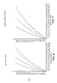
- FIG. 6 is a graph showing the results of a theoretical claculation of the force produced by a jump rope that does not elongate versus the turning revolution per minute (RPM) of the jump rope. Shown in Figure 6 is the force versus RPM plot for four ropes having different weights. "X” represents a two pound (0.9 kg) rope; “O” represents a three and one-half pound (1.6 kg) rope; “+” represents a five pound (2.3 kg) rope; and “I” represents a six pound (2.7 kg) rope.
- RPM turning revolution per minute
- the value 2.84 x 10 -5 is a centrifugal constant as reported in Machinery's Handbook (20th Ed.) pg. 338.
- the units of F, W, and r are, respectively, in pounds force, pounds and feet.
- the corresponding equation in SI units is where F is in Newtons, m is in kg, r is in metres and w is in radians per second.
- Chart 1 represents the raw data compiled in Figure 6, and Chart 1A represents the same thing in SI units.
- Figure 7 represents a theoretical calculation of the force in pound produced by the device 10a versus the turning RPM, for a device 10a manufactured from the above referenced polyisoprene material and according to the above dimensions for that material.
- the three and one-half pound (1.59 kg) device 10a increased by twenty-seven inches (68.6 cm) producing a value of 1.563.
- the five pound (2.3 kg) device 10a increased by twenty-one inches (53.3 cm) for a value of 1.438.
- the six pound (2.7 kg) device 10a increased by eighteen inches (45.7 cm) for a value of 1.375.
- Chart 2 represents the raw data compiled in Figure 7, and Chart 2A represents the same thing in SI units.
- the force exerted by the device 10a is increased nonlinearly with an increase in turning RPM, so that an increase in RPM will produce a disproportionately increased force upon the user's hands. Therefore, a person using the device 10a may increase the effect required by an exercise program by changing either of two variables, either using a heavier device 10a or by increasing turning RPM.
- the increased weight of the device 10a provides the device 10a with an increased angular momentum during use. After the-turning pattern is established, this angular momentum makes use of the device 10a easier for novices than standard jump ropes.
- the user maintains the motion of the device 10a by a more vertical movement of the forearmr at the elbow with some shoulder pivoting, shown in phantom in Figure 2, rather than a conventional circular motion. This effect is increased due to the "shock absorption" effect described below.
- the twisting forces that are exerted on a person's hands are reduced without the use of a conventional swivel coupling on the handles, although such a swivel coupling could be provided.
- the device 10a exercises the arms of the user as well as the user's legs.
- the device 10a circumscribes the user, it does not follow a circle in the manner of a standard jump rope.
- the path followed by the joining section 20 is oval shaped, with an enlarged extended region 27 behind the user and an enlarged region 28 in front of the user.
- the extended region 28 in front of the user is further removed from the user than the extended region 27 to the rear. It is believed that the oblong configuration of this path of travel is produced by the combined effect of the centrifugal and the gravitational forces acting upon the weighted joining section 20. Since the device 10a is moving generally downward in front of the user, it is belived that the centrifugal and gravitational forces are additive and thus produce the larger extended region 28.
- the joining section 20 fluctuates between regions closer to the person and the regions further removed from the person. As the joining section 20 fluctuates between these various regions, the elastomeric cord 12 resiliently varies in length and thus produces a "shock absorber" effect within the device 10a. This shock absorber effect prevents undesirable jolting from being imparted to the user's hands and arms during such transitions. Further, since the weighting material 14 is distributed through the flexible member 12, the device 10a is not completely unloaded when the joining section 20 strikes the floor.-The weighting material 14 extends up the legs 18 to maintain a load on the device. Also, the elongated legs 18.
- An exercise device 10b includes two elongated, tubular flexible members 30 made of the elastomeric latex material described above. As both halves of the exercise device 10b are identical, only one flexible member 30 is shown and described. Telescopingly received in the lower end of the flexible member 30 is a substantially non-elastomeric flexible joining member 32.
- the joining member 32 forms a joining section with the elastomeric flexible member 30 of the other side. Due to the resilient properties of the flexible member 30, the joining section 32 is securely frictionally connected thereton.
- a conventional adhesive may also be used to join the flexible member 30 to the joining section 32.
- the joining section 32 includes an aperture or channel 34 which is communicative with an aperture or channel 36 in the flexible member 30.
- This channel 34 is filled with particulate weighting material 38, preferably the silica material described above.
- the weighting material 38 fills the joining section 32 and extends us into the flexible members 30.
- On the upper end of each flexible member 30 is a handle 40.
- Each handle 40 includes a centre plug 42 that is received down into the aperture 36 and which prevents the escape of the particulate weighting material 38.
- the centre plug 42 has a rounded end 44 which permits the flexible member 30 to pivot about the centre plug 42 without scoring or otherwise damaging its inside surface.
- a rounded cap 46 Connected to the centre plug 42 is a rounded cap 46 which extends about the exterior of the flexible member 30 and includes a gripping surface thereon.
- Both the joining section 32 and the handles 40 are flexible in that they are readily bendable, but are preferably formed from a substantially non-elastomeric polymeric material.
- the exercise device 10b acts similarly to the exercise device 10a described above. However, since the predominate elongation of the exercise device 10a is confined to the depending legs 18 proximate the handles 22, the exercise device 10b only makes use of elastomeric material in the vicinity of the handles 40. Therefore, the flexible sections 30 are permitted to elongate while the joining section 32 provides separation between the flexible members 30.
- a turn buckle or ball joint may be included between the handle of the exercise device and the elastomeric flexible member.
- various handles having conventional designs and means of securing to flexible member 30 are within the contemplation of the invention.
- Shown in Figure 5 is a third preferred embodiment referenced as device 10c.
- This has a flexible, elastomeric cord 50 that is made from expanded foam polymeric material, and is solid.
- the polymeric material is mixed with a weighing agent prior to expansion or foaming so that the cord 50 results in an increased predetermined weight. Even though it is made of material having an increased weight, the cord 50 is still provided with the ability to resiliently elongate during use.
- the device 10c therefore provides a moment arm between the user's hands and the centre of gravity (or mass) of the device 10c that varies during use.
- On the upper end of the cord 50 is a polymeric cap 52 that forms a handle for the device 10c.
- the cap 52 has a suitable gripping surface, and due to the elastomeric properties of the cord 50 good hand feel is provided by the device 10c.
- Exemplary of an expanded elastomeric material for the cord 50 is polyisoprene having a blowing or expanding agent therein.
- One manufacturer of this polyisoprene material is Loran Manufacturing Company of New Philidelphia, Ohio.
- Examples of weighting agents which may be used in the cord 50 are lead or clay.
Landscapes
- Health & Medical Sciences (AREA)
- General Health & Medical Sciences (AREA)
- Physical Education & Sports Medicine (AREA)
- Rehabilitation Tools (AREA)
- Massaging Devices (AREA)
- Eye Examination Apparatus (AREA)
- Emergency Lowering Means (AREA)
- Ropes Or Cables (AREA)
- Harvester Elements (AREA)
- Electrical Discharge Machining, Electrochemical Machining, And Combined Machining (AREA)
Priority Applications (1)
| Application Number | Priority Date | Filing Date | Title |
|---|---|---|---|
| AT85303700T ATE43070T1 (de) | 1984-05-25 | 1985-05-24 | Uebungsvorrichtung. |
Applications Claiming Priority (2)
| Application Number | Priority Date | Filing Date | Title |
|---|---|---|---|
| US614329 | 1984-05-25 | ||
| US06/614,329 US4505474A (en) | 1984-05-25 | 1984-05-25 | Weighted elastomeric jumping device |
Publications (2)
| Publication Number | Publication Date |
|---|---|
| EP0163505A1 true EP0163505A1 (de) | 1985-12-04 |
| EP0163505B1 EP0163505B1 (de) | 1989-05-17 |
Family
ID=24460783
Family Applications (1)
| Application Number | Title | Priority Date | Filing Date |
|---|---|---|---|
| EP85303700A Expired EP0163505B1 (de) | 1984-05-25 | 1985-05-24 | Übungsvorrichtung |
Country Status (6)
| Country | Link |
|---|---|
| US (1) | US4505474A (de) |
| EP (1) | EP0163505B1 (de) |
| JP (1) | JPS60256470A (de) |
| AT (1) | ATE43070T1 (de) |
| CA (1) | CA1240720A (de) |
| DE (1) | DE3570190D1 (de) |
Families Citing this family (62)
| Publication number | Priority date | Publication date | Assignee | Title |
|---|---|---|---|---|
| US4593899A (en) * | 1980-05-09 | 1986-06-10 | Miller Robert A | Exercise jumping rope |
| US4733861A (en) * | 1985-11-29 | 1988-03-29 | Plunkett Iii Hugh V | Multi-use exercise device |
| KR890000870B1 (ko) * | 1986-06-09 | 1989-04-12 | 이석영 | 바벨 |
| US4949955A (en) * | 1988-07-19 | 1990-08-21 | Robert Keen | Exercise weight device for varying force during exercise motion |
| US5152523A (en) * | 1986-11-18 | 1992-10-06 | Robert Keen | Exercise weight device for varying force during exercise motion |
| US4801137A (en) * | 1987-10-26 | 1989-01-31 | Shane Douglass | Variable weight hand held exercise apparatus |
| WO1990000076A1 (en) * | 1988-06-29 | 1990-01-11 | Sportskip International Pty. Ltd. | An exercise device |
| US4919417A (en) * | 1988-08-15 | 1990-04-24 | Poulas Peter W | Liquid filled jump rope |
| US5007635A (en) * | 1989-04-12 | 1991-04-16 | Ralph Tiller | Exercise device |
| US4986535A (en) * | 1989-09-14 | 1991-01-22 | Hull Harold L | Variable weight exercise device |
| US5092583A (en) * | 1990-12-14 | 1992-03-03 | Rudolf John L | Aerobic and resistance exerciser |
| US5312314A (en) * | 1993-01-06 | 1994-05-17 | Stephan Paul B | Exercise yoke |
| US5364325A (en) * | 1993-06-18 | 1994-11-15 | Matthews Douglas R | Leveraged weight compounding system |
| US5393284A (en) * | 1993-12-29 | 1995-02-28 | Wesley; Jerry L. | Flexible barbell exercise apparatus |
| US5833587A (en) * | 1996-02-09 | 1998-11-10 | Pebd Ltd. | Apparatus and method for exercising |
| US5904640A (en) * | 1997-02-14 | 1999-05-18 | Shahinian; Araz R. | Extended centripetal rotator exercise device |
| AU2348299A (en) * | 1998-02-02 | 1999-08-16 | Arnold J. Cook | Jump rope |
| US6077194A (en) * | 1999-09-14 | 2000-06-20 | Chang; Wei-Hwang | Body twist exercising toy with sound and light producing means |
| US7169091B2 (en) * | 2000-02-01 | 2007-01-30 | St George David | Skipping rope or jump rope having improved asymmetric handle |
| GB2358809B (en) | 2000-02-01 | 2002-12-24 | Clayton O'shea | Skipping ropes |
| US7341544B2 (en) * | 2000-02-01 | 2008-03-11 | St George David | Skipping rope or jump rope having improved asymmetric handle |
| USD452891S1 (en) | 2000-05-25 | 2002-01-08 | Bollinger Industries, L.P. | Jump rope with thickened section |
| US6598260B1 (en) * | 2000-07-28 | 2003-07-29 | Michael D. Sharpe | Liquid barrier system |
| NL1020853C2 (nl) * | 2002-06-13 | 2003-12-16 | Ronald Raoul Lambert | Trainingsinrichting. |
| US7074687B2 (en) * | 2003-04-04 | 2006-07-11 | Freescale Semiconductor, Inc. | Method for forming an ESD protection device |
| US8075455B2 (en) * | 2007-08-28 | 2011-12-13 | Borg Unlimited, Inc. | Jump rope handle exercise device |
| US8038585B1 (en) * | 2008-09-17 | 2011-10-18 | Brown Jr Gordon L | Flexible elongated handheld exercise bars |
| WO2012151273A1 (en) * | 2011-05-02 | 2012-11-08 | Get Arm Strength, Llc | Strength training aid |
| US9056216B1 (en) | 2011-08-02 | 2015-06-16 | Kevin Bouza | Jump rope |
| US8911333B2 (en) | 2011-12-22 | 2014-12-16 | CrossRope, LLC | Jump rope device comprising a removably-connected cable |
| US8951173B2 (en) * | 2012-05-21 | 2015-02-10 | Marcus Kovach | Exercise apparatus |
| WO2014153158A1 (en) | 2013-03-14 | 2014-09-25 | Icon Health & Fitness, Inc. | Strength training apparatus with flywheel and related methods |
| EP3086865B1 (de) | 2013-12-26 | 2020-01-22 | Icon Health & Fitness, Inc. | Mechanismus des magnetischen widerstands in einer kabelmaschine |
| WO2015138339A1 (en) | 2014-03-10 | 2015-09-17 | Icon Health & Fitness, Inc. | Pressure sensor to quantify work |
| US10426989B2 (en) | 2014-06-09 | 2019-10-01 | Icon Health & Fitness, Inc. | Cable system incorporated into a treadmill |
| USD736863S1 (en) | 2014-06-20 | 2015-08-18 | iBalanS LLC | Exercise device |
| US9795821B2 (en) | 2014-09-19 | 2017-10-24 | Doree Feldman | Garment with weighted elastic portion |
| US10258828B2 (en) | 2015-01-16 | 2019-04-16 | Icon Health & Fitness, Inc. | Controls for an exercise device |
| US10071274B2 (en) | 2015-07-24 | 2018-09-11 | Gravity Rope, Llc | Jump rope device |
| US9757604B2 (en) * | 2015-08-18 | 2017-09-12 | Matthew Roderick Carter | Multipurpose exercise training device |
| US10953305B2 (en) | 2015-08-26 | 2021-03-23 | Icon Health & Fitness, Inc. | Strength exercise mechanisms |
| WO2017151709A1 (en) * | 2016-03-01 | 2017-09-08 | Gravity Rope, Llc | Jump rope device |
| US10625137B2 (en) | 2016-03-18 | 2020-04-21 | Icon Health & Fitness, Inc. | Coordinated displays in an exercise device |
| US10272317B2 (en) | 2016-03-18 | 2019-04-30 | Icon Health & Fitness, Inc. | Lighted pace feature in a treadmill |
| US10561894B2 (en) | 2016-03-18 | 2020-02-18 | Icon Health & Fitness, Inc. | Treadmill with removable supports |
| US10293211B2 (en) | 2016-03-18 | 2019-05-21 | Icon Health & Fitness, Inc. | Coordinated weight selection |
| US10493349B2 (en) | 2016-03-18 | 2019-12-03 | Icon Health & Fitness, Inc. | Display on exercise device |
| US10252109B2 (en) | 2016-05-13 | 2019-04-09 | Icon Health & Fitness, Inc. | Weight platform treadmill |
| US10441844B2 (en) | 2016-07-01 | 2019-10-15 | Icon Health & Fitness, Inc. | Cooling systems and methods for exercise equipment |
| US10471299B2 (en) | 2016-07-01 | 2019-11-12 | Icon Health & Fitness, Inc. | Systems and methods for cooling internal exercise equipment components |
| US10500473B2 (en) | 2016-10-10 | 2019-12-10 | Icon Health & Fitness, Inc. | Console positioning |
| US10376736B2 (en) | 2016-10-12 | 2019-08-13 | Icon Health & Fitness, Inc. | Cooling an exercise device during a dive motor runway condition |
| US10661114B2 (en) | 2016-11-01 | 2020-05-26 | Icon Health & Fitness, Inc. | Body weight lift mechanism on treadmill |
| TWI646997B (zh) | 2016-11-01 | 2019-01-11 | 美商愛康運動與健康公司 | 用於控制台定位的距離感測器 |
| TWI680782B (zh) | 2016-12-05 | 2020-01-01 | 美商愛康運動與健康公司 | 於操作期間抵銷跑步機的平台之重量 |
| US11451108B2 (en) | 2017-08-16 | 2022-09-20 | Ifit Inc. | Systems and methods for axial impact resistance in electric motors |
| US10549137B2 (en) * | 2017-11-01 | 2020-02-04 | Greg Tousant | Pendulum jump rope |
| WO2019099701A1 (en) | 2017-11-20 | 2019-05-23 | Haslam Ryan | Jump rope with spring-supported collet handle |
| US10729965B2 (en) | 2017-12-22 | 2020-08-04 | Icon Health & Fitness, Inc. | Audible belt guide in a treadmill |
| US10981029B2 (en) * | 2018-09-10 | 2021-04-20 | Fmfc Llc | Exercise tubing for high intensity interval training and methods of use |
| US11229814B1 (en) | 2021-04-28 | 2022-01-25 | Bosu Fitness, Llc | Dynamic training device |
| US11607572B1 (en) * | 2021-05-06 | 2023-03-21 | David Bradley | Multi-purpose jump fitness, resistance strength and boxing training device, system and method |
Citations (4)
| Publication number | Priority date | Publication date | Assignee | Title |
|---|---|---|---|---|
| US148489A (en) * | 1874-03-10 | Improvement in skipfing-rods | ||
| US3107916A (en) * | 1961-11-03 | 1963-10-22 | William A Cooper | Sprinkling jump rope |
| US3762704A (en) * | 1972-05-19 | 1973-10-02 | Raymond Lee Organization Inc | Telescopic jump rope toy with selective latching structure |
| US4090705A (en) * | 1977-03-21 | 1978-05-23 | Ross Young | Jump rope |
Family Cites Families (3)
| Publication number | Priority date | Publication date | Assignee | Title |
|---|---|---|---|---|
| US1817616A (en) * | 1929-05-24 | 1931-08-04 | William F Goff | Jumping rope |
| US4109906A (en) * | 1976-01-15 | 1978-08-29 | Wilson Bradford W | Skip rope |
| US4177985A (en) * | 1977-10-03 | 1979-12-11 | Hlasnicek Jean F | Jump rope with variable weighting and rope configuration |
-
1984
- 1984-05-25 US US06/614,329 patent/US4505474A/en not_active Expired - Lifetime
-
1985
- 1985-05-03 CA CA000480725A patent/CA1240720A/en not_active Expired
- 1985-05-24 AT AT85303700T patent/ATE43070T1/de not_active IP Right Cessation
- 1985-05-24 JP JP60111965A patent/JPS60256470A/ja active Pending
- 1985-05-24 DE DE8585303700T patent/DE3570190D1/de not_active Expired
- 1985-05-24 EP EP85303700A patent/EP0163505B1/de not_active Expired
Patent Citations (4)
| Publication number | Priority date | Publication date | Assignee | Title |
|---|---|---|---|---|
| US148489A (en) * | 1874-03-10 | Improvement in skipfing-rods | ||
| US3107916A (en) * | 1961-11-03 | 1963-10-22 | William A Cooper | Sprinkling jump rope |
| US3762704A (en) * | 1972-05-19 | 1973-10-02 | Raymond Lee Organization Inc | Telescopic jump rope toy with selective latching structure |
| US4090705A (en) * | 1977-03-21 | 1978-05-23 | Ross Young | Jump rope |
Also Published As
| Publication number | Publication date |
|---|---|
| DE3570190D1 (en) | 1989-06-22 |
| EP0163505B1 (de) | 1989-05-17 |
| ATE43070T1 (de) | 1989-06-15 |
| CA1240720A (en) | 1988-08-16 |
| JPS60256470A (ja) | 1985-12-18 |
| US4505474A (en) | 1985-03-19 |
Similar Documents
| Publication | Publication Date | Title |
|---|---|---|
| EP0163505B1 (de) | Übungsvorrichtung | |
| US5529562A (en) | Exercise apparatus | |
| US5842956A (en) | Strength resistance training jump rope | |
| US4900017A (en) | Inertial force, accommodating resistance exercise device and method | |
| US7833133B2 (en) | End of travel stop for an exercise device | |
| EP1938869B1 (de) | Zusätzliche Widerstandsanordnung für die Widerstandsbewegung eines Übungsgerätes | |
| US5820531A (en) | Sand filled exercise stick | |
| US11148001B2 (en) | Exercise system | |
| US7179210B2 (en) | Club-weight(s) | |
| US4693469A (en) | Aerobic exercise device | |
| US20220347508A1 (en) | Dynamic training device | |
| US5044626A (en) | Exercise apparatus having asymmetrical impact cushions and methods of exercising selected muscle groups by direct force application | |
| US10357689B2 (en) | Selectable speed bag support apparatus | |
| US5222930A (en) | Inertial force exercise device having dense body extremities | |
| US20130190145A1 (en) | Dynamic Weight Training Apparatus | |
| US4775147A (en) | Inertial force exercise device having three independent rotational inertia systems | |
| US20230191183A1 (en) | Fitness and rehabilitation aid | |
| US9724557B2 (en) | Exercise apparatus | |
| US20200353302A1 (en) | Counter-balanced exercise systems and methods | |
| CN212522883U (zh) | 一种蹲起训练架 | |
| KR101992856B1 (ko) | 운동기구 | |
| CN223774238U (zh) | 武术抗阻力训练器材 | |
| CN210472919U (zh) | 一种基于跑步机用减震跑带 | |
| CN110215652B (zh) | 一种组合式体育器材 | |
| RU156069U1 (ru) | Тренажер для фитнеса |
Legal Events
| Date | Code | Title | Description |
|---|---|---|---|
| PUAI | Public reference made under article 153(3) epc to a published international application that has entered the european phase |
Free format text: ORIGINAL CODE: 0009012 |
|
| AK | Designated contracting states |
Designated state(s): AT BE CH DE FR GB IT LI LU NL SE |
|
| 17P | Request for examination filed |
Effective date: 19860528 |
|
| 17Q | First examination report despatched |
Effective date: 19870716 |
|
| ITF | It: translation for a ep patent filed | ||
| GRAA | (expected) grant |
Free format text: ORIGINAL CODE: 0009210 |
|
| AK | Designated contracting states |
Kind code of ref document: B1 Designated state(s): AT BE CH DE FR GB IT LI LU NL SE |
|
| PG25 | Lapsed in a contracting state [announced via postgrant information from national office to epo] |
Ref country code: AT Effective date: 19890517 |
|
| REF | Corresponds to: |
Ref document number: 43070 Country of ref document: AT Date of ref document: 19890615 Kind code of ref document: T |
|
| REF | Corresponds to: |
Ref document number: 3570190 Country of ref document: DE Date of ref document: 19890622 |
|
| ET | Fr: translation filed | ||
| PLBE | No opposition filed within time limit |
Free format text: ORIGINAL CODE: 0009261 |
|
| STAA | Information on the status of an ep patent application or granted ep patent |
Free format text: STATUS: NO OPPOSITION FILED WITHIN TIME LIMIT |
|
| 26N | No opposition filed | ||
| PGFP | Annual fee paid to national office [announced via postgrant information from national office to epo] |
Ref country code: GB Payment date: 19920323 Year of fee payment: 8 |
|
| PGFP | Annual fee paid to national office [announced via postgrant information from national office to epo] |
Ref country code: LU Payment date: 19920403 Year of fee payment: 8 |
|
| PGFP | Annual fee paid to national office [announced via postgrant information from national office to epo] |
Ref country code: SE Payment date: 19920423 Year of fee payment: 8 |
|
| PGFP | Annual fee paid to national office [announced via postgrant information from national office to epo] |
Ref country code: FR Payment date: 19920514 Year of fee payment: 8 |
|
| PGFP | Annual fee paid to national office [announced via postgrant information from national office to epo] |
Ref country code: DE Payment date: 19920527 Year of fee payment: 8 |
|
| ITTA | It: last paid annual fee | ||
| PGFP | Annual fee paid to national office [announced via postgrant information from national office to epo] |
Ref country code: NL Payment date: 19920531 Year of fee payment: 8 |
|
| PGFP | Annual fee paid to national office [announced via postgrant information from national office to epo] |
Ref country code: BE Payment date: 19920616 Year of fee payment: 8 |
|
| PGFP | Annual fee paid to national office [announced via postgrant information from national office to epo] |
Ref country code: CH Payment date: 19920715 Year of fee payment: 8 |
|
| EPTA | Lu: last paid annual fee | ||
| PG25 | Lapsed in a contracting state [announced via postgrant information from national office to epo] |
Ref country code: LU Free format text: LAPSE BECAUSE OF NON-PAYMENT OF DUE FEES Effective date: 19930524 Ref country code: GB Effective date: 19930524 |
|
| PG25 | Lapsed in a contracting state [announced via postgrant information from national office to epo] |
Ref country code: SE Effective date: 19930525 |
|
| PG25 | Lapsed in a contracting state [announced via postgrant information from national office to epo] |
Ref country code: LI Effective date: 19930531 Ref country code: CH Effective date: 19930531 Ref country code: BE Effective date: 19930531 |
|
| BERE | Be: lapsed |
Owner name: MATTOX ERNEST MICHAEL Effective date: 19930531 |
|
| PG25 | Lapsed in a contracting state [announced via postgrant information from national office to epo] |
Ref country code: NL Effective date: 19931201 |
|
| NLV4 | Nl: lapsed or anulled due to non-payment of the annual fee | ||
| GBPC | Gb: european patent ceased through non-payment of renewal fee |
Effective date: 19930524 |
|
| PG25 | Lapsed in a contracting state [announced via postgrant information from national office to epo] |
Ref country code: FR Effective date: 19940131 |
|
| REG | Reference to a national code |
Ref country code: CH Ref legal event code: PL |
|
| PG25 | Lapsed in a contracting state [announced via postgrant information from national office to epo] |
Ref country code: DE Effective date: 19940201 |
|
| REG | Reference to a national code |
Ref country code: FR Ref legal event code: ST |
|
| EUG | Se: european patent has lapsed |
Ref document number: 85303700.0 Effective date: 19931210 |