EP0163571A1 - Procédé de fabrication par extrusions multiples de tubes allégés, rigides, en matiéres thermoplastiques - Google Patents
Procédé de fabrication par extrusions multiples de tubes allégés, rigides, en matiéres thermoplastiques Download PDFInfo
- Publication number
- EP0163571A1 EP0163571A1 EP85400933A EP85400933A EP0163571A1 EP 0163571 A1 EP0163571 A1 EP 0163571A1 EP 85400933 A EP85400933 A EP 85400933A EP 85400933 A EP85400933 A EP 85400933A EP 0163571 A1 EP0163571 A1 EP 0163571A1
- Authority
- EP
- European Patent Office
- Prior art keywords
- blank
- thermoplastic material
- rigid
- expanded
- extrusion
- Prior art date
- Legal status (The legal status is an assumption and is not a legal conclusion. Google has not performed a legal analysis and makes no representation as to the accuracy of the status listed.)
- Withdrawn
Links
- 239000012815 thermoplastic material Substances 0.000 title claims abstract description 36
- 238000001125 extrusion Methods 0.000 title claims abstract description 29
- 238000000034 method Methods 0.000 title claims abstract description 24
- 239000002131 composite material Substances 0.000 claims abstract description 11
- 239000000203 mixture Substances 0.000 claims abstract description 6
- 239000000463 material Substances 0.000 claims description 12
- 239000004033 plastic Substances 0.000 claims description 11
- 229920003023 plastic Polymers 0.000 claims description 11
- 238000004519 manufacturing process Methods 0.000 claims description 9
- 239000004604 Blowing Agent Substances 0.000 claims description 5
- 239000012530 fluid Substances 0.000 claims description 5
- 239000003795 chemical substances by application Substances 0.000 abstract description 2
- 238000004513 sizing Methods 0.000 abstract 1
- 239000007789 gas Substances 0.000 description 7
- PPBRXRYQALVLMV-UHFFFAOYSA-N Styrene Chemical compound C=CC1=CC=CC=C1 PPBRXRYQALVLMV-UHFFFAOYSA-N 0.000 description 4
- 230000001105 regulatory effect Effects 0.000 description 4
- 229920001577 copolymer Polymers 0.000 description 3
- 239000004800 polyvinyl chloride Substances 0.000 description 3
- 239000004156 Azodicarbonamide Substances 0.000 description 2
- XOZUGNYVDXMRKW-AATRIKPKSA-N azodicarbonamide Chemical compound NC(=O)\N=N\C(N)=O XOZUGNYVDXMRKW-AATRIKPKSA-N 0.000 description 2
- 235000019399 azodicarbonamide Nutrition 0.000 description 2
- 230000001413 cellular effect Effects 0.000 description 2
- 238000010586 diagram Methods 0.000 description 2
- 239000011261 inert gas Substances 0.000 description 2
- -1 polypropylene Polymers 0.000 description 2
- 229920000915 polyvinyl chloride Polymers 0.000 description 2
- 229920001169 thermoplastic Polymers 0.000 description 2
- 239000004416 thermosoftening plastic Substances 0.000 description 2
- 238000003466 welding Methods 0.000 description 2
- NLHHRLWOUZZQLW-UHFFFAOYSA-N Acrylonitrile Chemical compound C=CC#N NLHHRLWOUZZQLW-UHFFFAOYSA-N 0.000 description 1
- 239000004698 Polyethylene Substances 0.000 description 1
- 239000004743 Polypropylene Substances 0.000 description 1
- 239000004793 Polystyrene Substances 0.000 description 1
- 230000015572 biosynthetic process Effects 0.000 description 1
- DPDORTBBLUCNJG-UHFFFAOYSA-N calcium tin Chemical compound [Ca].[Sn] DPDORTBBLUCNJG-UHFFFAOYSA-N 0.000 description 1
- 239000011248 coating agent Substances 0.000 description 1
- 238000000576 coating method Methods 0.000 description 1
- 238000001816 cooling Methods 0.000 description 1
- 238000009826 distribution Methods 0.000 description 1
- 230000000694 effects Effects 0.000 description 1
- 238000009434 installation Methods 0.000 description 1
- 239000007788 liquid Substances 0.000 description 1
- FPYJFEHAWHCUMM-UHFFFAOYSA-N maleic anhydride Chemical compound O=C1OC(=O)C=C1 FPYJFEHAWHCUMM-UHFFFAOYSA-N 0.000 description 1
- 239000011159 matrix material Substances 0.000 description 1
- 238000012986 modification Methods 0.000 description 1
- 230000004048 modification Effects 0.000 description 1
- 230000035515 penetration Effects 0.000 description 1
- 229920000573 polyethylene Polymers 0.000 description 1
- 229920000098 polyolefin Polymers 0.000 description 1
- 229920001155 polypropylene Polymers 0.000 description 1
- 229920002223 polystyrene Polymers 0.000 description 1
- 229920005989 resin Polymers 0.000 description 1
- 239000011347 resin Substances 0.000 description 1
- 239000007787 solid Substances 0.000 description 1
- 239000000126 substance Substances 0.000 description 1
- 238000011144 upstream manufacturing Methods 0.000 description 1
- 125000000391 vinyl group Chemical group [H]C([*])=C([H])[H] 0.000 description 1
- 229920002554 vinyl polymer Polymers 0.000 description 1
- 238000004804 winding Methods 0.000 description 1
Images
Classifications
-
- B—PERFORMING OPERATIONS; TRANSPORTING
- B29—WORKING OF PLASTICS; WORKING OF SUBSTANCES IN A PLASTIC STATE IN GENERAL
- B29C—SHAPING OR JOINING OF PLASTICS; SHAPING OF MATERIAL IN A PLASTIC STATE, NOT OTHERWISE PROVIDED FOR; AFTER-TREATMENT OF THE SHAPED PRODUCTS, e.g. REPAIRING
- B29C44/00—Shaping by internal pressure generated in the material, e.g. swelling or foaming ; Producing porous or cellular expanded plastics articles
- B29C44/20—Shaping by internal pressure generated in the material, e.g. swelling or foaming ; Producing porous or cellular expanded plastics articles for articles of indefinite length
- B29C44/22—Shaping by internal pressure generated in the material, e.g. swelling or foaming ; Producing porous or cellular expanded plastics articles for articles of indefinite length consisting of at least two parts of chemically or physically different materials, e.g. having different densities
-
- B—PERFORMING OPERATIONS; TRANSPORTING
- B29—WORKING OF PLASTICS; WORKING OF SUBSTANCES IN A PLASTIC STATE IN GENERAL
- B29C—SHAPING OR JOINING OF PLASTICS; SHAPING OF MATERIAL IN A PLASTIC STATE, NOT OTHERWISE PROVIDED FOR; AFTER-TREATMENT OF THE SHAPED PRODUCTS, e.g. REPAIRING
- B29C44/00—Shaping by internal pressure generated in the material, e.g. swelling or foaming ; Producing porous or cellular expanded plastics articles
- B29C44/34—Auxiliary operations
- B29C44/36—Feeding the material to be shaped
- B29C44/46—Feeding the material to be shaped into an open space or onto moving surfaces, i.e. to make articles of indefinite length
- B29C44/50—Feeding the material to be shaped into an open space or onto moving surfaces, i.e. to make articles of indefinite length using pressure difference, e.g. by extrusion or by spraying
- B29C44/507—Feeding the material to be shaped into an open space or onto moving surfaces, i.e. to make articles of indefinite length using pressure difference, e.g. by extrusion or by spraying extruding the compound through an annular die
-
- B—PERFORMING OPERATIONS; TRANSPORTING
- B29—WORKING OF PLASTICS; WORKING OF SUBSTANCES IN A PLASTIC STATE IN GENERAL
- B29C—SHAPING OR JOINING OF PLASTICS; SHAPING OF MATERIAL IN A PLASTIC STATE, NOT OTHERWISE PROVIDED FOR; AFTER-TREATMENT OF THE SHAPED PRODUCTS, e.g. REPAIRING
- B29C48/00—Extrusion moulding, i.e. expressing the moulding material through a die or nozzle which imparts the desired form; Apparatus therefor
- B29C48/001—Combinations of extrusion moulding with other shaping operations
- B29C48/0013—Extrusion moulding in several steps, i.e. components merging outside the die
- B29C48/0015—Extrusion moulding in several steps, i.e. components merging outside the die producing hollow articles having components brought in contact outside the extrusion die
- B29C48/0016—Extrusion moulding in several steps, i.e. components merging outside the die producing hollow articles having components brought in contact outside the extrusion die using a plurality of extrusion dies
-
- B—PERFORMING OPERATIONS; TRANSPORTING
- B29—WORKING OF PLASTICS; WORKING OF SUBSTANCES IN A PLASTIC STATE IN GENERAL
- B29C—SHAPING OR JOINING OF PLASTICS; SHAPING OF MATERIAL IN A PLASTIC STATE, NOT OTHERWISE PROVIDED FOR; AFTER-TREATMENT OF THE SHAPED PRODUCTS, e.g. REPAIRING
- B29C48/00—Extrusion moulding, i.e. expressing the moulding material through a die or nozzle which imparts the desired form; Apparatus therefor
- B29C48/03—Extrusion moulding, i.e. expressing the moulding material through a die or nozzle which imparts the desired form; Apparatus therefor characterised by the shape of the extruded material at extrusion
- B29C48/09—Articles with cross-sections having partially or fully enclosed cavities, e.g. pipes or channels
-
- B—PERFORMING OPERATIONS; TRANSPORTING
- B29—WORKING OF PLASTICS; WORKING OF SUBSTANCES IN A PLASTIC STATE IN GENERAL
- B29C—SHAPING OR JOINING OF PLASTICS; SHAPING OF MATERIAL IN A PLASTIC STATE, NOT OTHERWISE PROVIDED FOR; AFTER-TREATMENT OF THE SHAPED PRODUCTS, e.g. REPAIRING
- B29C48/00—Extrusion moulding, i.e. expressing the moulding material through a die or nozzle which imparts the desired form; Apparatus therefor
- B29C48/16—Articles comprising two or more components, e.g. co-extruded layers
- B29C48/18—Articles comprising two or more components, e.g. co-extruded layers the components being layers
- B29C48/21—Articles comprising two or more components, e.g. co-extruded layers the components being layers the layers being joined at their surfaces
-
- B—PERFORMING OPERATIONS; TRANSPORTING
- B29—WORKING OF PLASTICS; WORKING OF SUBSTANCES IN A PLASTIC STATE IN GENERAL
- B29C—SHAPING OR JOINING OF PLASTICS; SHAPING OF MATERIAL IN A PLASTIC STATE, NOT OTHERWISE PROVIDED FOR; AFTER-TREATMENT OF THE SHAPED PRODUCTS, e.g. REPAIRING
- B29C48/00—Extrusion moulding, i.e. expressing the moulding material through a die or nozzle which imparts the desired form; Apparatus therefor
- B29C48/001—Combinations of extrusion moulding with other shaping operations
- B29C48/0018—Combinations of extrusion moulding with other shaping operations combined with shaping by orienting, stretching or shrinking, e.g. film blowing
-
- B—PERFORMING OPERATIONS; TRANSPORTING
- B29—WORKING OF PLASTICS; WORKING OF SUBSTANCES IN A PLASTIC STATE IN GENERAL
- B29C—SHAPING OR JOINING OF PLASTICS; SHAPING OF MATERIAL IN A PLASTIC STATE, NOT OTHERWISE PROVIDED FOR; AFTER-TREATMENT OF THE SHAPED PRODUCTS, e.g. REPAIRING
- B29C48/00—Extrusion moulding, i.e. expressing the moulding material through a die or nozzle which imparts the desired form; Apparatus therefor
- B29C48/03—Extrusion moulding, i.e. expressing the moulding material through a die or nozzle which imparts the desired form; Apparatus therefor characterised by the shape of the extruded material at extrusion
- B29C48/09—Articles with cross-sections having partially or fully enclosed cavities, e.g. pipes or channels
- B29C48/10—Articles with cross-sections having partially or fully enclosed cavities, e.g. pipes or channels flexible, e.g. blown foils
-
- B—PERFORMING OPERATIONS; TRANSPORTING
- B29—WORKING OF PLASTICS; WORKING OF SUBSTANCES IN A PLASTIC STATE IN GENERAL
- B29K—INDEXING SCHEME ASSOCIATED WITH SUBCLASSES B29B, B29C OR B29D, RELATING TO MOULDING MATERIALS OR TO MATERIALS FOR MOULDS, REINFORCEMENTS, FILLERS OR PREFORMED PARTS, e.g. INSERTS
- B29K2105/00—Condition, form or state of moulded material or of the material to be shaped
- B29K2105/04—Condition, form or state of moulded material or of the material to be shaped cellular or porous
-
- B—PERFORMING OPERATIONS; TRANSPORTING
- B29—WORKING OF PLASTICS; WORKING OF SUBSTANCES IN A PLASTIC STATE IN GENERAL
- B29L—INDEXING SCHEME ASSOCIATED WITH SUBCLASS B29C, RELATING TO PARTICULAR ARTICLES
- B29L2023/00—Tubular articles
- B29L2023/22—Tubes or pipes, i.e. rigid
Definitions
- the present invention relates to a process for manufacturing, by multiple extrusions, lightened, rigid, and composite wall tubes of thermoplastic materials, as well as the tube obtained.
- the compact wall was provided with rigid PVC tubes with longitudinal circular cavities or multi-wall tubes were created by extrusion, or by helical winding of an extruded profile, or that the particular properties of rigid plastics lightened by expansion have been used.
- This last widely used technique has made it possible to develop rigid products in expanded material which can be used in building and public works.
- various attempts have been made to improve them, which consist in stiffening the expanded material by producing the plastic tubes in the form of composite tubes comprising external and internal layers of solid thermoplastic material and an intermediate layer. made of expanded thermoplastic material, as described in French patent FR-A-2,391,058 and in American patent US-A-4 322 260.
- Such tubes can be manufactured by coextrusion of the different layers as described in French patent FR-A- 2 391 058.
- this technique requires the use of a single heated and regulated coextrusion head which simultaneously receives from a first extruder the compact thermoplastic material and from a second extruder the thermoplastic material containing a blowing agent, and different channels to lead the assembly to the matrix training.
- This coextrusion head is therefore complex to produce and / or to implement, which constitutes a drawback.
- the present invention specifically relates to a method of manufacturing by multiple extrusions of plastic tubes, lightened, rigid and with a composite wall, which overcomes the drawbacks of the methods described above.
- the method of the invention thus makes it possible to simplify the manufacture of tubes with a composite wall by carrying out the two-stage extrusion of the expanded core and of the external surface of compact material. Thanks to this arrangement, it is now possible to use conventional tools (head-die-punch), to vary the thickness of the outer layer as desired, to remove the shrinkage phenomena inherent in the methods of manufacturing the prior art, phenomena which are due to the stresses generated in the expanded core or in the two compact layers, during the expansion of the cellular core.
- the expansion can be carried out under good conditions and in particular obtain a radial expansion, which was not the case in the processes of prior art where expansion was carried out between two layers of compact material in French patent FR-A- 2,391,058 or on a compact layer in American patent US-A- 4,322,260. expansion is generally 5 to 50%, for example about 25%.
- the plastic tube of the invention which only comprises a core of expanded thermoplastic material and an outer covering layer of compact material is thus easier to produce than the tubes of the prior art comprising a core of expanded thermoplastic material sandwiched between two compact layers.
- the invention it is also possible, if desired, to obtain a smooth and dense film on the internal surface of the tube by subjecting the internal surface of the blank of the tube, during the expansion step b), to the action of a cold gaseous fluid.
- the fluid used can be air, an inert gas or more generally a gas which does not react with the thermoplastic material used.
- this blank is made under vacuum of rigid expanded material in a hot calibrator, before carrying out the step. c) extruding the rigid compact layer of thermoplastic material.
- a slight gas pressure is maintained inside the blank leaving the first extruder.
- gases used can be, as before, air or inert gases. This allows the expanded material to be pressurized at the level of the second extruder, the adjustment of the positioning of the maximum expansion can be carried out by appropriately adjusting the pressure of the gas inside the blank to help it. to swell.
- thermoplastic material used to form the expanded core can be identical to the thermoplastic material used to form the rigid layer.
- thermoplastic material used to form the rigid layer can be identical to the thermoplastic material used to form the rigid layer.
- PVC polyvinyl chloride
- polystyrene polystyrene
- copolymers of styrene and acrylonitrile copolymers of styrene and maleic anhydride
- acrylonitrile copolymers - butadiene - styrene and polyolefins such as polypropylene and polyethylene.
- blowing agents for example azodicarbonamide.
- the invention also relates to rigid light plastic tubes manufactured according to the method of the present invention and which prove to be insensitive to the withdrawal phenomena previously described.
- the method of manufacturing by multiple extrusions of tubes lightweight, rigid and composite-walled plastics uses a first extruder (1) constituted for example by an extruder of the KMD 90 type (not shown) provided with a conventional head (2), with a conventional die (3), with a conventional punch (4) and which allows the manufacture of a tube blank (or extrudate) (5) produced from a mixture of rigid PVC such as PVCK Wert 67 stabilized with tin calcium , marketed by Limburgse Vinyl Maatschappij, and blowing agents such as azodicarbonamide.
- a first extruder (1) constituted for example by an extruder of the KMD 90 type (not shown) provided with a conventional head (2), with a conventional die (3), with a conventional punch (4) and which allows the manufacture of a tube blank (or extrudate) (5) produced from a mixture of rigid PVC such as PVCK Wert 67 stabilized with tin calcium , marketed by Limburgse Vinyl Maatschappij, and blowing agents
- the tube blank (5) begins its expansion in the open air and comes to conform in a calibrator (6) under vacuum, centered by adjusting screw ( 7), heated and temperature controlled to allow adhesion by continuous welding and at extrusion temperature of a second extrudate forming a covering layer (8) and coming from the secondary extruder (9) (not shown) located perpendicularly to the main extrusion axis.
- This extrudate (8) is applied to the expanded extrudate (5) using an extrusion die ring (10) attached to the secondary extruder (9).
- the centering of the covering layer (8) is adjusted by action on adjusting screws (11) acting on the finishing die (12).
- the thickness of the covering layer enveloping the expanded extrudate (5) is determined by the ribs of the extrusion finishing die (12).
- the composite product thus obtained at the outlet of the extrusion finishing die (12) is shaped in a conventional cold calibrator (13) giving the tube its final appearance, then cooled in the appropriate conventional tanks (19).
- a slight pressure for example of the order of 0.15.10 5 P a (150 g / cm 2 ) is maintained inside the tube blank by a gaseous product blocked by an internal gauge (14), distributed by a distribution head (15), and supplied by a supply pipe (16).
- the gaseous product is cooled more or less strongly and a circulation of the gaseous fluid regulated by means of a pressure regulator (18) must be provided in order to keep the desired cooling temperature constant, the fluid being evacuated via line 21.
- the blank in expanded material is not conformed in a hot calibrator before covering it with the rigid layer of thermoplastic material.
- a slight gas pressure or- dr of 0,15.10 5 P 150 g / cm 2 ), which makes it possible to pressurize the blank (5) at the level of the extrusion die ring (10) of the second extruder.
- the adjustment of the positioning of the maximum expansion is carried out, on the one hand, by advancing or reversing the first extruder and, on the other hand, by regulating the gas pressure inside the blank for the help inflate.
- the gas outlet (21) can be replaced by an exhaust (20) formed in the internal gauge (14), the gaseous product injected by the apple (15) is then regulated by the pressure regulator (18) , the pipe (16) is connected upstream before penetration into the extrusion punch to a bypass connected to a tube plunging of a greater or lesser height in a Liquid to allow the release of overpressures.
- This effect is comparable to that of an adjustable valve.
- the thickness of the various layers is determined by the dimensions of the different tools (punches and bits), the centering is carried out by action on the adjusting screws (7 and 11) which act on the channels according to the usual methods.
- the appearance of the tubes was good and the shrinkage was less than 3 X.
- the density of the tubes was about 1 and their weight per m of 1.6 kg. Pressure tests carried out at 20 ° C at 1 MPa (10 bar) for 1 hour have given satisfactory results.
- thermoplastic tubes the device can also be used successfully and without making novation for the realization of hollow or full profits in thermoplastic material.
Landscapes
- Engineering & Computer Science (AREA)
- Mechanical Engineering (AREA)
- Extrusion Moulding Of Plastics Or The Like (AREA)
Abstract
Procédé de fabrication par extrusions multiples de tubes allégés, rigides, en matières thermoplastiques.
Ce procédé se caractérise en ce que:
- a) on prépare par extrusion, dans une première extrudeuse (1), une ébauche (5) du tube à partir d'un mélange de matière thermoplastique et d'agent d'expansion,
- b) on laisse expanser dans toutes les directions l'ébauche ainsi obtenue,
- c) on extrude ensuite directement sur l'ébauche du tube en matière thermoplastique expansée, chauffée et conformée, au moins une couche (8) compacte, rigide de matière thermoplastique formant couche de recouvrement, et
- d) on conforme l'ébauche composite ainsi obtenue dans un calibreur froid classique (13).
Les tubes obtenus peuvent être utilisés comme tubes d'adduction d'eau.
Description
- La présente invention concerne un procédé de fabrication par extrusions multiples de tubes allégés, rigides, et à paroi composite en matières thermoplastiques ainsi que Le tube obtenu.
- Les tubes plastiques compacts sont couramment utilisés depuis ces vingt dernières années pour La confection des canalisations enterrées en raison de leur facilité de pose et de leurs qualités physiques et chimiques particulières. Ils pâtissent malheureusement de deux inconvénients majeurs : leur manque de rigidité qui se traduit par une faiblesse à l'écrasement, ainsi que leur prix,compte tenu des hausses substantielles du coût des résines. Des solutions ont donc été apportées pour résoudre ce double problème et se sont traduites par des techniques variées d'allègement et de rigidification de La paroi des tubes.
- C'est ainsi par exemple que l'on a doté La paroi compacte de tubes en PVC rigide de cavités circulaires longitudinales ou que l'on a créé par extrusion, ou par enroulement hélicoïdal d'un profilé extrudé, des tubes à parois multiples, ou encore que l'on a utilisé les propriétés particulières des plastiques rigides allégés par expansion. Cette dernière technique largement répandue a permis La mise au point de produits rigides en matière expansée utilisables dans Le bâtiment et les travaux publics. Malgré l'intérêt certain de ces produits, différentes tentatives ont été effectuées pour les améliorer et qui consistent à rigidifier la matière expansée en réalisant les tubes plastiques sous la forme de tubes composites comportant des couches externe et interne en matière thermoplastique massive et une couche intermédiaire en matériau thermoplastique expansé, comme cela est décrit dans le brevet français FR-A- 2 391 058 et dans le brevet américain US-A- 4 322 260. De tels tubes peuvent être fabriqués par coextrusion des différentes couches comme cela est décrit dans le brevet français FR-A- 2 391 058. Cependant, cette technique nécessite l'emploi d'une seule tête de coextrusion chauffée et régulée qui reçoit simultanément d'une première extrudeuse la matière thermoplastique compacte et d'une deuxième extrudeuse la matière thermoplastique contenant un agent d'expansion, et des canaux différents pour conduire l'ensemble jusqu'à la matrice de formation. Cette tête de coextrusion est donc complexe à réaliser et/ou à mettre en oeuvre, ce qui constitue un inconvénient.
- On a aussi envisagé de réaliser de tels tubes par extrusions multiples en réalisant tout d'abord le tube interne, que l'on revêt ensuite par extrusion de la couche de matière thermoplastique expansée qui est elle-même revêtue par extrusion de la couche externe en matière thermoplastique compacte, comme cela est décrit dans le brevet américain US-A- 4 322 260.
- Cependant, cette technique présente aussi certains inconvénients, en particulier celui de conduire à des tensions internes dans le matériau car la couche de matière thermoplastique expansée est extrudée sur un tube rigide et les contraintes ne peuvent être Libérées au moment de l'expansion, ce qui provoque L'apparition de tensions internes conduisant à une fragilisation du matériau.
- La présente invention a précisément pour objet un procédé de fabrication par extrusions multiples de tubes plastiques, allégés, rigides et à paroi composite, qui pallie les inconvénients des procédés décrits ci- dessus.
- Le procédé selon l'invention de fabrication par extrusions multiples d'un tube plastique; allégé, rigide, à paroi composite, se caractérise en ce que:
- a) on prépare par extrusion, dans une première extrudeuse, une ébauche du tube à partir d'un mélange de matière thermoplastique et d'agent d'expansion,
- b) on laisse expanser dans toutes les directions L'ébauche ainsi obtenue
- c) on extrude ensuite directement sur l'ébauche du tube en matière thermoplastique expansée, chauffée et conformée, au moins une couche compacte rigide de matière thermoplastique formant couche de recouvrement, et
- d) on conforme L'ébauche composite ainsi obtenue dans un calibreur froid classique.
- Le procédé de l'invention permet ainsi de simplifier la fabrication des tubes à paroi composite en réalisant L'extrusion en deux temps de l'âme expansée et de la surface externe en matériau compact . Grâce à cet agencement, il est désormais possible d'utiliser des outillages classiques (tête-filière-poinçon), de faire varier à volonté l'épaisseur de La couche externe, de supprimer les phénomènes de retrait inhérents aux modes de fabrication de l'art antérieur, phénomènes qui sont dus aux contraintes engendrées dans l'âme expansée ou dans les deux couches compactes, lors de l'expansion de l'âme cellulaire.
- En effet, en réalisant, tout d'abord, l'âme cellulaire en matière thermoplastique expansée, on peut réaliser l'expansion dans de bonnes conditions et obtenir en particulier une expansion radiale, ce qui n'était pas le cas dans les procédés de l'art antérieur où l'on réalisait l'expansion entre deux couches de matière compacte dans Le brevet français FR-A- 2 391 058 ou sur une couche compacte dans le brevet américain US-A- 4 322 260. Le taux d'expansion est généralement de 5 à 50 %,par exemple d'environ 25 %.
- Le tube plastique de L'invention qui comporte uniquement une âme en matière thermoplastique expansée et une couche externe de recouvrement en matière compacte est ainsi plus facile à réaliser que les tubes de l'art antérieur comportant une âme en matière thermoplastique expansée prise en sandwich entre deux couches compactes.
- Selon l'invention, on peut aussi, si on le désire, obtenir une pellicule lisse et dense sur la surface interne du tube en soumettant la surface interne de l'ébauche du tube, lors de l'étape d'expansion b), à l'action d'un fluide gazeux froid. Le fluide utilisé peut être de l'air, un gaz inerte ou plus généralement un gaz ne réagissant pas avec la matière thermoplastique utilisée.
- Ceci permet d'obtenir des tubes plastiques ayant une surface interne tisse, ce qui est généralement recherché lorsque ces tubes sont destinés à être utilisés pour L'assainissement.
- Selon un mode préféré de mise en oeuvre du procédé de l'invention, après l'étape b) d'expansion de L'ébauche, on conforme sous vide cette ébauche en matière expansée rigide dans un calibreur chaud, avant de réaliser L'étape c) d'extrusion de La couche compacte rigide de matière thermoplastique.
- Ceci permet d'obtenir une meilleure adhérence par soudage en continu de la couche de recouvrement provenant de la deuxième extrudeuse.
- De préférence, notamment lorsque L'ébauche n'est pas conforméesous vide dans un calibreur chaud, on maintient une légère pression de gaz à l'intérieur de L'ébauche sortant de la première extrudeuse. Les gaz utilisés peuvent être comme précédemment de l'air ou des gaz inertes. Ceci permet de conformer sous pression La matière expansée au niveau de la deuxième extrudeuse, l'ajustement du positionnement de L'expansion maximale pouvant être effectué en réglant de façon appropriée la pression du gaz à l'intérieur de l'ébauche pour l'aider à se gonfler.
- On peut aussi maintenir une légère pression à l'intérieur de l'ébauche lorsque celle-ci est conformée sous vide dans un calibreur chaud, car ceci favorise l'application de L'ébauche dans Le calibreur chaud, puis le calibreur froid, et permet d'éviter son affaissement lors de l'extrusion de La couche compacte rigide de matière thermoplastique formant couche de recouvrement.
- Dans Le procédé de l'invention, La matière thermoplastique utilisée pour former l'âme expansée peut être identique à la matière thermoplastique utilisée pour former La couche rigide. Cependant, on peut aussi utiliser pour réaliser la couche rigide et l'ébauche, des matières thermoplastiques différentes dans la mesure où celles-ci sont compatibles entre elles.
- A titre d'exemple de matières thermoplastiques susceptibles d'être utilisées, on peut citer le chlorure de polyvinyle (PVC), le polystyrène, les copolymères de styrène et d'acrylonitrile, les copolymères de styrène et d'anhydride maléique, les copolymères acrylonitrile-- butadiène - styrène, et les polyoléfines telles que le polypropylène et le polyéthylène.
- Pour la formation de L'ébauche en matière thermoplastique expansée, on utilise des agents d'expansion classiques, par exemple de l'azodicarbonamide.
- L'invention concerne également les tubes plastiques allégés rigides fabriqués selon le procédé de La présente invention et qui s'avèrent peu sensibles aux phénomènes de retrait précédemment décrits.
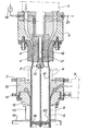
- Certains détails de L'invention seront mieux compris à la lecture de La description suivante faite en relation avec la figure unique annexée qui en présente un schéma de principe.
- Comme représenté sur le schéma de principe, le procédé de fabrication par extrusions multiples de tubes plastiques allégés, rigides et à paroi composite suivant l'invention met en oeuvre une première extrudeuse (1) constituée par exemple par une extrudeuse du type KMD 90 (non représentée) munie d'une tête classique (2), d'une filière classique (3), d'un poinçon classique (4) et qui permet la fabrication d'une ébauche de tube (ou extrudat) (5) réalisé à partir d'un mélange de PVC rigide tel que le PVCK Wert 67 stabilisé au calcium étain, commercialisé par Limburgse Vinyl Maatschappij, et d'agents d'expansion tels que l'azodicarbonamide. A la sortie de La filière (3) de l'extrudeuse principale, L'ébauche de tube (5) commence son expansion à l'air libre et vient se conformer dans un calibreur (6) sous vide, centré par vis de réglage (7), chauffé et régulé en température pour permettre une adhérence par soudage en continu et à température d'extrusion d'un deuxième extrudat formant couche de recouvrement (8) et provenant de l'extrudeuse secondaire (9) (non représentée) située perpendiculairement à l'axe principal d'extrusion. Cet extrudat (8) est appliqué sur l'extrudat expansé (5) à l'aide d'un anneau filière d'extrusion (10) rattaché à l'extrudeuse secondaire (9). Le centrage de la couche de recouvrement (8) est réglé par action sur des vis de réglage (11) agissant sur la filière de finition (12).
- L'épaisseur de la couche de recouvrement enveloppant l'extrudat expansé (5) est déterminée par les côtes de la filière de finition d'extrusion (12).
- Le produit composite ainsi obtenu à La sortie de la filière de finition d'extrusion (12) est conformé dans un calibreur froid (13) classique donnant au tube son aspect définitif, puis refroidi dans les bacs classiques appropriés (19). Pour favoriser l'application de l'ébauche expansée (5) issue de la première extrudeuse dans les calibreurs (6 et 13) et éviter son affaissement pendant son enduction par l`extrudat secondaire (8), une légère pression, par exemple de l'ordre de 0,15.105 Pa (150 g/cm2), est maintenue à l'intérieur de l'ébauche de tube par un produit gazeux bloqué par un calibre interne (14), distribué par une pomme de répartition (15), et alimenté par une conduite d'amenée (16). Dans le cas où l'on désire La formation, simultanément à l'expansion de l'ébauche, d'une pellicule Lisse (17) plus ou moins importante sur La surface interne du tube, Le produit gazeux est refroidi plus ou moins fortement et l'on doit prévoir une circulation du fluide gazeux régulée au moyen d'un mano-détendeur (18) afin de maintenir constante la température souhaitée de refroidissement, Le fluide étant évacué par la conduite 21.
- Selon une variante de mise en oeuvre du procédé de l'invention, on ne conforme pas L'ébauche en matière expansée dans un calibreur chaud avant de La recouvrir de la couche rigide de matière thermoplastique. Dans ce cas, on maintient à l'intérieur de l'ébauche (5) sortant de l'extrudeuse (1), une légère pression de gaz de l'or- dre de 0,15.105 Pa (150 g/cm2), ce qui permet de conformer sous pression l'ébauche (5) au niveau de l'anneau- filière d'extrusion (10) de la deuxième extrudeuse. L'ajustement du positionnement de L'expansion maximale s'effectue, d'une part, en avançant ou reculant la première extrudeuse et, d'autre part, en réglant la pression de gaz à L'intérieur de L'ébauche pour L'aider à se gonfler. Dans ce cas, on peut remplacer la sortie de gaz (21) par un échappement (20) ménagé dans Le calibre intérieur (14), le produit gazeux injecté par la pomme (15) est alors régulé par le mano-détendeur (18), la conduite (16) est raccordée en amont avant pénétration dans le poinçon d'extrusion à une dérivation raccordée à un tube plongeant d'une hauteur plus ou moins importante dans un Liquide afin de permettre le dégagement des surpressions. Cet effet est comparable à celui d'une soupape réglable.
- Dans les deux modes de mise en oeuvre du procédé, L'épaisseur des diverses couches est déterminée par les cotes des différents outillages (poinçons et fitières), les centrages sont effectués par action sur les vis de réglage (7 et 11) qui agissent sur les filières selon les méthodes habituelles.
- Par te procédé de l'invention, on peut réaliser des tubes rigides, allégés, multicouches, ayant un diamètre de 32 à 1000 mm avec une couche externe compacte ayant une épaisseur de 0,5 à 7 mm et une couche interne de matière thermoplastique expansée ayant une épaisseur de 1 à 25 mm.
- A titre d'exemple, on a fabriqué des tubes d'assainissement ayant un diamètre externe de 125 mm, une épaisseur totale de 4 mm et une longueur de 6 m, L'épaisseur de la couche compacte étant de 1 mm et L'épaisseur de La couche de matière thermoplastique expansée de 3 mm,dans les conditions suivantes :
- - température des différentes zones des deux extrudeuses réglée entre 130° et 210°C,
- - vitesse de la vis d'extrusion : 12 tr/min,
- - vitesse de la vis du doseur : 18 tr/min,
- - couple d'extrusion : 55 X,
- - poussée axiale : 4 tonnes,
- - pression dans le calibreur (13) : (0,230 atm) 0,23.105 Pa,
- L'aspect des tubes était bon et le retrait a été inférieur à 3 X. La densité des tubes était d'environ 1 et leur poids par m de 1,6 kg. Des essais de pression effectués à 20°C sous 1 MPa (10 bars) pendant 1 heure ont donné des résultats satisfaisants.
- La présente invention n'est pas Limitée aux exemples de réalisation qui viennent d'être décrits, elle est au contraire susceptible de variantes et de modifications qui apparaîtront à l'homme de l'art, comme par exemple de prévoir sur une même ligne d'extrusion plusieurs extrudeuses secondaires fonctionnant suivant le procédé décrit dans l'invention, utilisant des matières thermoplastiques de composition identique ou non, et disposant des couches successives de matière avant le passage dans le calibreur froid.(13).
- IL est bien entendu que si l'application préférentielle de l'invention concerne les tubes thermoplastiques, le dispositif peut également être utilisé avec succès et sans faire novation pour la réalisation de profités creux ou pleins en matière thermoplastique.
Claims (5)
1. Procédé de fabrication par extrusions multiples d'un tube plastique, allégé, rigide, à paroi composite, caractérisé en ce que:
a) on prépare par extrusion, dans une première extrudeuse (1), une ébauche (5) du tube à partir d'un mélange de matière thermoplastique et d'agent d'expansion,
b) on laisse expanser dans toutes les directions L'ébauche ainsi obtenue,
c) on extrude ensuite directement sur t'ébauche du tube en matière thermoplastique expansée, chauffée et conformée, au moins une couche (8) compacte, rigide de matière thermoplastique formant couche de recouvrement, et
d) on conforme l'ébauche composite ainsi obtenue dans un calibreur froid classique (13).
2. Procédé selon La revendication 1, caractérisé en ce que, après L'étape d'expansion b) de l'ébauche, on conforme sous vide l'ébauche en matière expansée rigide dans un calibreur chaud (6), avant de réaliser l'étape c) d'extrusion de la couche compacte rigide de matière thermoplastique.
3. Procédé selon l'une quelconque des revendications 1 et 2, caractérisé en ce que l'on forme sur La surface interne du tube, une pellicule (17) lisse et dense en soumettant la surface interne de l'ébauche, lors de son expansion, à l'action d'un fluide gazeux froid.
4. Procédé selon l'une quelconque des revendications 1 à 3, caractérisé en ce que La matière thermoplastique de la couche compacte rigide de recouvrement est différente de la matière thermoplastique constituant l'ébauche expansée.
5. Tubes plastiques obtenus par mise en oeuvre du procédé suivant l'une quelconque des revendications 1 à 5.
Applications Claiming Priority (2)
| Application Number | Priority Date | Filing Date | Title |
|---|---|---|---|
| FR8407709 | 1984-05-18 | ||
| FR8407709A FR2564375B1 (fr) | 1984-05-18 | 1984-05-18 | Procede de fabrication de tubes alleges, rigides en matiere thermoplastique |
Publications (1)
| Publication Number | Publication Date |
|---|---|
| EP0163571A1 true EP0163571A1 (fr) | 1985-12-04 |
Family
ID=9304112
Family Applications (1)
| Application Number | Title | Priority Date | Filing Date |
|---|---|---|---|
| EP85400933A Withdrawn EP0163571A1 (fr) | 1984-05-18 | 1985-05-13 | Procédé de fabrication par extrusions multiples de tubes allégés, rigides, en matiéres thermoplastiques |
Country Status (2)
| Country | Link |
|---|---|
| EP (1) | EP0163571A1 (fr) |
| FR (1) | FR2564375B1 (fr) |
Cited By (4)
| Publication number | Priority date | Publication date | Assignee | Title |
|---|---|---|---|---|
| DE3907106C1 (fr) * | 1989-03-04 | 1989-11-16 | Friedrichsfeld Gmbh Keramik- Und Kunststoffwerke, 6800 Mannheim, De | |
| EP0556665A1 (fr) * | 1992-02-18 | 1993-08-25 | FRIEDRICH THEYSOHN GmbH | Procédé pour la fabrication d'un tuyau en matière plastique |
| CN108237672A (zh) * | 2018-01-16 | 2018-07-03 | 深圳市安特迈科技有限公司 | 挤出机模头及挤出机 |
| GB2593559A (en) * | 2019-09-02 | 2021-09-29 | Ro Lee Kyung | Device for forming a protective pipe having integrated inner and outer pipes, and protective pipe formed thereby |
Families Citing this family (1)
| Publication number | Priority date | Publication date | Assignee | Title |
|---|---|---|---|---|
| CN106113534B (zh) * | 2016-06-20 | 2019-03-26 | 宁夏青龙塑料管材有限公司 | 一种pert保温管道一步法成型工艺 |
Citations (7)
| Publication number | Priority date | Publication date | Assignee | Title |
|---|---|---|---|---|
| DE2042031A1 (de) * | 1970-08-25 | 1972-05-31 | Reifenhaeuser Kg | Verfahren und Vorrichtung zur Herstellung von Wellrohren aus thermoplastischem Kunststoff |
| FR2183814A1 (fr) * | 1972-05-05 | 1973-12-21 | Wacker Chemie Gmbh | |
| US3876740A (en) * | 1972-10-27 | 1975-04-08 | Standard Oil Co | Process for improving interior surface smoothness and gloss in foamed tubular extrudates by the use of extrusion die faces of novel geometry |
| DE2618071A1 (de) * | 1976-04-24 | 1977-11-10 | Berstorff Gmbh Masch Hermann | Verfahren und vorrichtung zur herstellung von kaschierten thermoplastischen schaumstoffbahnen |
| FR2391058A1 (fr) * | 1977-05-16 | 1978-12-15 | Borg Warner | Procede de fabrication de tuyaux en materiau thermoplastique rigides et legers |
| US4322260A (en) * | 1979-04-04 | 1982-03-30 | Monsanto Company | Process for the continuous extrusion forming of a plastic double-walled foam-core conduit |
| EP0084360B1 (fr) * | 1982-01-14 | 1987-05-20 | Sekisui Kaseihin Kogyo Kabushiki Kaisha | Feuille pour fabriquer un manchon et son procédé de fabrication |
-
1984
- 1984-05-18 FR FR8407709A patent/FR2564375B1/fr not_active Expired
-
1985
- 1985-05-13 EP EP85400933A patent/EP0163571A1/fr not_active Withdrawn
Patent Citations (7)
| Publication number | Priority date | Publication date | Assignee | Title |
|---|---|---|---|---|
| DE2042031A1 (de) * | 1970-08-25 | 1972-05-31 | Reifenhaeuser Kg | Verfahren und Vorrichtung zur Herstellung von Wellrohren aus thermoplastischem Kunststoff |
| FR2183814A1 (fr) * | 1972-05-05 | 1973-12-21 | Wacker Chemie Gmbh | |
| US3876740A (en) * | 1972-10-27 | 1975-04-08 | Standard Oil Co | Process for improving interior surface smoothness and gloss in foamed tubular extrudates by the use of extrusion die faces of novel geometry |
| DE2618071A1 (de) * | 1976-04-24 | 1977-11-10 | Berstorff Gmbh Masch Hermann | Verfahren und vorrichtung zur herstellung von kaschierten thermoplastischen schaumstoffbahnen |
| FR2391058A1 (fr) * | 1977-05-16 | 1978-12-15 | Borg Warner | Procede de fabrication de tuyaux en materiau thermoplastique rigides et legers |
| US4322260A (en) * | 1979-04-04 | 1982-03-30 | Monsanto Company | Process for the continuous extrusion forming of a plastic double-walled foam-core conduit |
| EP0084360B1 (fr) * | 1982-01-14 | 1987-05-20 | Sekisui Kaseihin Kogyo Kabushiki Kaisha | Feuille pour fabriquer un manchon et son procédé de fabrication |
Cited By (5)
| Publication number | Priority date | Publication date | Assignee | Title |
|---|---|---|---|---|
| DE3907106C1 (fr) * | 1989-03-04 | 1989-11-16 | Friedrichsfeld Gmbh Keramik- Und Kunststoffwerke, 6800 Mannheim, De | |
| EP0556665A1 (fr) * | 1992-02-18 | 1993-08-25 | FRIEDRICH THEYSOHN GmbH | Procédé pour la fabrication d'un tuyau en matière plastique |
| CN108237672A (zh) * | 2018-01-16 | 2018-07-03 | 深圳市安特迈科技有限公司 | 挤出机模头及挤出机 |
| GB2593559A (en) * | 2019-09-02 | 2021-09-29 | Ro Lee Kyung | Device for forming a protective pipe having integrated inner and outer pipes, and protective pipe formed thereby |
| GB2593559B (en) * | 2019-09-02 | 2022-04-13 | Ro Lee Kyung | Apparatus for forming a protecting duct with integrated inner and outer walls, and the duct formed thereby |
Also Published As
| Publication number | Publication date |
|---|---|
| FR2564375A1 (fr) | 1985-11-22 |
| FR2564375B1 (fr) | 1987-03-06 |
Similar Documents
| Publication | Publication Date | Title |
|---|---|---|
| EP0019564B1 (fr) | Procédé et appareillage pour l'extrusion de tubes plastiques à parois composites | |
| US3223761A (en) | Melt extrusion of multi-wall plastic tubing | |
| US3354506A (en) | Apparatus for melt extrusion of multi-wall plastic tubing | |
| CA2174996C (fr) | Procede de fabrication de produits extrudes remplis de mousse | |
| CA2229842C (fr) | Produits polymeres orientes | |
| FR2551694A1 (fr) | ||
| EP3131738B1 (fr) | Procédé et dispositif d'extrusion et étiquetage d'un tube d'emballage | |
| FR2622833A1 (fr) | Procede et installation pour la fabrication d'objets moules ou extrudes a partir de dechets contenant des matieres plastiques | |
| US2700631A (en) | Method of providing articles with a plastic coating | |
| JP3471924B2 (ja) | スパイラルダイおよびこれを用いる積層体製造方法 | |
| US5862591A (en) | Method for manufacturing paint rollers | |
| US4289727A (en) | Method for extrusion of tubular films | |
| FR2609663A1 (fr) | Procede de fabrication de films a partir de polymeres fluides semi-cristallins, par coextrusion et soufflage de gaine | |
| FR2564375A1 (fr) | Procede de fabrication de tubes alleges, rigides en matiere thermoplastique | |
| JPH0229315A (ja) | 多層シート材料及びその製法 | |
| NO158747B (no) | Fremgangsmaate ved fremstilling av krympegjenstander. | |
| FR2540782A1 (fr) | Procede pour fabriquer un conduit thermiquement isolant pour produire un tube | |
| BE1006667A3 (fr) | Procede pour realiser, par coextrusion, un tuyau allege et filiere pour sa realisation. | |
| FR2580542A1 (fr) | Procede d'extrusion de matieres plastiques expansibles | |
| EP0693650B1 (fr) | Article composite et procédé pour sa fabrication | |
| FR2462254A1 (fr) | Tubes et profiles biorientes en matiere thermoplastique et leur procede de fabrication | |
| JP3210534B2 (ja) | プラスチック擬木と、プラスチック擬木の製造方法およびその製造方法に用いられる連結ジョイナー | |
| CA2075738C (fr) | Procede de fabrication de tubes a choc par coextrusion | |
| JPS583817B2 (ja) | ホオンカンノ セイゾウホウホウ | |
| FR2752193A1 (fr) | Procede et installation de fabrication en continu d'une bande metallique revetue d'une couche d'un polymere |
Legal Events
| Date | Code | Title | Description |
|---|---|---|---|
| PUAI | Public reference made under article 153(3) epc to a published international application that has entered the european phase |
Free format text: ORIGINAL CODE: 0009012 |
|
| AK | Designated contracting states |
Designated state(s): BE CH DE FR GB IT LI NL |
|
| 17P | Request for examination filed |
Effective date: 19860509 |
|
| STAA | Information on the status of an ep patent application or granted ep patent |
Free format text: STATUS: THE APPLICATION IS DEEMED TO BE WITHDRAWN |
|
| 18D | Application deemed to be withdrawn |
Effective date: 19871130 |
|
| RIN1 | Information on inventor provided before grant (corrected) |
Inventor name: BOULY, MARCEAU |