EP0163586A2 - Piezoelektrische Zündvorrichtung - Google Patents
Piezoelektrische Zündvorrichtung Download PDFInfo
- Publication number
- EP0163586A2 EP0163586A2 EP85420078A EP85420078A EP0163586A2 EP 0163586 A2 EP0163586 A2 EP 0163586A2 EP 85420078 A EP85420078 A EP 85420078A EP 85420078 A EP85420078 A EP 85420078A EP 0163586 A2 EP0163586 A2 EP 0163586A2
- Authority
- EP
- European Patent Office
- Prior art keywords
- sheath
- sleeve
- anvil
- stopper
- piezoelectric element
- Prior art date
- Legal status (The legal status is an assumption and is not a legal conclusion. Google has not performed a legal analysis and makes no representation as to the accuracy of the status listed.)
- Withdrawn
Links
- 239000004020 conductor Substances 0.000 claims abstract description 7
- 239000004952 Polyamide Substances 0.000 claims description 3
- 239000000463 material Substances 0.000 claims description 3
- 229920002647 polyamide Polymers 0.000 claims description 3
- 229930182556 Polyacetal Natural products 0.000 claims description 2
- 229920006324 polyoxymethylene Polymers 0.000 claims description 2
- 239000002184 metal Substances 0.000 description 4
- 238000004519 manufacturing process Methods 0.000 description 3
- 239000000853 adhesive Substances 0.000 description 2
- 230000001070 adhesive effect Effects 0.000 description 2
- 239000004840 adhesive resin Substances 0.000 description 2
- 229920006223 adhesive resin Polymers 0.000 description 2
- 238000006073 displacement reaction Methods 0.000 description 2
- 230000000694 effects Effects 0.000 description 2
- 239000013013 elastic material Substances 0.000 description 1
- 238000010292 electrical insulation Methods 0.000 description 1
- 238000002347 injection Methods 0.000 description 1
- 239000007924 injection Substances 0.000 description 1
- 230000037431 insertion Effects 0.000 description 1
- 238000003780 insertion Methods 0.000 description 1
- 239000012212 insulator Substances 0.000 description 1
- 210000000056 organ Anatomy 0.000 description 1
- 238000009877 rendering Methods 0.000 description 1
- 230000003313 weakening effect Effects 0.000 description 1
Images
Classifications
-
- F—MECHANICAL ENGINEERING; LIGHTING; HEATING; WEAPONS; BLASTING
- F23—COMBUSTION APPARATUS; COMBUSTION PROCESSES
- F23Q—IGNITION; EXTINGUISHING-DEVICES
- F23Q3/00—Igniters using electrically-produced sparks
- F23Q3/002—Igniters using electrically-produced sparks using piezoelectric elements
Definitions
- the present invention relates to a piezoelectric ignition device, in particular, although not exclusively, for a gas lighter.
- the piezoelectric ignition devices generally comprise a tubular sheath mounted axially movable between two extreme positions, respectively extended and retracted, in a tubular body closed by a bottom, at one of its ends, this tubular sheath containing, starting from its outer end, an anvil made of electrically conductive material, a piezoelectric element and a cylindrical element forming a stopper, also made of an electrically conductive material, these three members being axially connected to the sheath by being pressed axially, one against the other, a striker associated with spring means being provided to strike against the stopper at the end of the re-entering stroke of the sleeve, the first part of which is used to band the associated spring means to the striker while other spring means normally tend to return and maintain the sheath in its extreme out position.
- the axial immobilization of the metal cylinder is generally obtained by an internal shoulder of the bore of the sheath while those of the piezoelectric element and the anvil are generally obtained using an adhesive resin.
- the layer formed by the adhesive resin has the advantage of constituting a good insulator between the two poles of the piezoelectric element, but it also has the drawback of being long and difficult to install, of being fragile, to break easily and, by its rigidity, to limit the deformations of the piezoelectric element which has the effect of weakening the electric power of the piezoelectric element until rendering the igniter unusable.
- the present invention aims to remedy all these drawbacks.
- the internal transverse dimensions of the sheath are slightly smaller than the transverse dimensions of the stopper, the piezoelectric element and the anvil, so that their axial fixation in the sheath is ensured by simple wedging or radial stress, used to generate their axial pressurization.
- the sheath is made of an elastically deformable material improving the radial stressing of the three members.
- a material which is perfectly suitable for making up the sheath is a polyamide or a polyacetaJ.
- the anvil carries at least one radial notch and, on the other hand, the sheath has a lateral window capable of receiving and retaining the notch of the anvil after axial tensioning of the sheath.
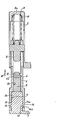
- this device essentially comprises a tubular body (2) closed, at one of its ends, by a bottom (2a) and in which is mounted a tubular sheath (3) axially movable between two extreme positions, exit and return respectively.
- the figure of the drawing shows the body (2) and the sleeve (3) in the extended position of the sleeve (3) relative to the body (2). It is further specified that the axial movement of the sheath (3) relative to the body (2) is relative, that is to say that it can result either from a displacement of the sheath (3), or from a displacement of the body (2).
- anvil (4) Inside the sheath (3) are housed, starting from the outer end of the latter, an anvil (4) of metal or other electrically conductive material, a piezoelectric element (5) and a stopper (6) also made of metal or other electrically conductive material.
- the anvil (4) carries, at its end corresponding to the external end of the sheath (3), a radial tab (7) constituting one of the electrodes of this ignition device.
- an axially movable striker (8) Inside the inner end of the sheath (3) and of the body (2), is also housed an axially movable striker (8), with which is associated a helical spring (9) compressed between it and the bottom (2a ) of the body (2).
- this device results from the increase in the mutual engagement of the sheath (3) and of the body (2) against the springs (9) and (11), which are compressed by this increase in engagement means, not described here, having the effect of allowing the striker (8) to be driven by the sheath (3) to the vicinity of its re-entrant end of travel and its release when the sheath (3) reaches its end of travel re-entrant, so that the rebound of the spring (9) projects the striker (8) against the stopper (6).
- These means are described in detail in European patent application No. 84420149.1 in the name of the Applicant.
- the object of the present application relates to the axial fixing of the anvil (4), of the piezoelectric element (5) and of the stopper (6) in the sheath (3), it being recalled that this axial position must allow axial pressurization of these three elements, that is to say generate between them an axial stress.
- the external transverse dimensions of the anvil (4), of the piezoelectric element (5) and the stopper (6) are slightly greater than those of each bore of the sleeve (3), respectively (3a) and (3b), provided to receive them. It follows that the engagement of these three organs (4,5,6) in the sleeve (3) generates, on each of them, a radial stress intended to ensure its axial fixing and also making it possible to generate between them the axial stress necessary for the operation of this device.
- the axial immobilization of the stopper (6) in the direction of the arrow (12) is advantageously obtained by a shoulder (13) provided inside the bore (3b) of the sleeve ( 3) and cooperating with a shoulder (6a) of the stopper (6).
- the conditions of axial stressing of the members (4,5,6) are improved by the use, for the production of the sheath (3), of a deformable elastic material such as, for example, a polyamide or a polyacetal.
- a piezoelectric ignition device of simple constitution is thus obtained, easy to manufacture, since it is no longer necessary to inject an adhesive with all the drawbacks associated with this injection and which, moreover, has the advantage to allow regular and unsurprising manufacturing and, therefore, to obtain a reliable device and safe operation.
Landscapes
- Engineering & Computer Science (AREA)
- Chemical & Material Sciences (AREA)
- Combustion & Propulsion (AREA)
- Mechanical Engineering (AREA)
- General Engineering & Computer Science (AREA)
- Ignition Installations For Internal Combustion Engines (AREA)
- Lighters Containing Fuel (AREA)
- Measuring Fluid Pressure (AREA)
Applications Claiming Priority (2)
| Application Number | Priority Date | Filing Date | Title |
|---|---|---|---|
| JP1984077093U JPS60190056U (ja) | 1984-05-28 | 1984-05-28 | 圧電点火器に於ける圧電素子取付装置 |
| JP77093/84U | 1984-05-28 |
Publications (2)
| Publication Number | Publication Date |
|---|---|
| EP0163586A2 true EP0163586A2 (de) | 1985-12-04 |
| EP0163586A3 EP0163586A3 (de) | 1986-12-17 |
Family
ID=13624164
Family Applications (1)
| Application Number | Title | Priority Date | Filing Date |
|---|---|---|---|
| EP85420078A Withdrawn EP0163586A3 (de) | 1984-05-28 | 1985-04-29 | Piezoelektrische Zündvorrichtung |
Country Status (5)
| Country | Link |
|---|---|
| EP (1) | EP0163586A3 (de) |
| JP (1) | JPS60190056U (de) |
| AU (1) | AU4301585A (de) |
| DK (1) | DK203885A (de) |
| PT (1) | PT80442B (de) |
Cited By (1)
| Publication number | Priority date | Publication date | Assignee | Title |
|---|---|---|---|---|
| FR2650654A1 (fr) * | 1989-08-02 | 1991-02-08 | Laforest Sa | Mecanisme piezo-electrique pour briquets a gaz |
Families Citing this family (1)
| Publication number | Priority date | Publication date | Assignee | Title |
|---|---|---|---|---|
| FR2674004B1 (fr) * | 1991-03-13 | 1995-12-08 | Laforest Bic Sa | Mecanisme piezo-electrique pour briquets a gaz. |
Family Cites Families (5)
| Publication number | Priority date | Publication date | Assignee | Title |
|---|---|---|---|---|
| GB1182762A (en) * | 1968-02-16 | 1970-03-04 | Brush Clevite Company Ltd | Piezoelectric Unit |
| GB1302025A (de) * | 1969-01-10 | 1973-01-04 | ||
| GB1319101A (en) * | 1970-06-05 | 1973-06-06 | Vernitron Ltd | Piezoelectric units and igniter devices |
| US3771943A (en) * | 1971-03-23 | 1973-11-13 | Ranson Corp | Lighter |
| FR2270526B1 (de) * | 1974-05-09 | 1978-06-02 | Rv Const Electriques |
-
1984
- 1984-05-28 JP JP1984077093U patent/JPS60190056U/ja active Pending
-
1985
- 1985-04-29 EP EP85420078A patent/EP0163586A3/de not_active Withdrawn
- 1985-05-08 DK DK203885A patent/DK203885A/da not_active Application Discontinuation
- 1985-05-10 PT PT80442A patent/PT80442B/pt unknown
- 1985-05-27 AU AU43015/85A patent/AU4301585A/en not_active Abandoned
Cited By (1)
| Publication number | Priority date | Publication date | Assignee | Title |
|---|---|---|---|---|
| FR2650654A1 (fr) * | 1989-08-02 | 1991-02-08 | Laforest Sa | Mecanisme piezo-electrique pour briquets a gaz |
Also Published As
| Publication number | Publication date |
|---|---|
| JPS60190056U (ja) | 1985-12-16 |
| DK203885D0 (da) | 1985-05-08 |
| AU4301585A (en) | 1985-12-05 |
| EP0163586A3 (de) | 1986-12-17 |
| PT80442A (fr) | 1985-06-01 |
| DK203885A (da) | 1985-11-29 |
| PT80442B (fr) | 1986-10-28 |
Similar Documents
| Publication | Publication Date | Title |
|---|---|---|
| EP0235041B1 (de) | Verriegelungsvorrichtung, zum Beispiel für einen Riegelverschluss | |
| EP0246934B1 (de) | Elektrischer Verbinder | |
| FR2674004A1 (fr) | Mecanisme piezo-electrique pour briquets a gaz. | |
| EP3399532B1 (de) | Nothaltevorrichtung | |
| CA1224840A (fr) | Mecanisme d'allumeur piezo-electrique | |
| FR2498740A1 (fr) | Allumeur piezo-electrique du type a percussion et bouton-poussoir | |
| EP0163586A2 (de) | Piezoelektrische Zündvorrichtung | |
| EP0133068A1 (de) | Sicherheitsschloss | |
| EP1613858A2 (de) | Elektromagnetisches einrückrelais für die steuerung eines elektrischen starters | |
| FR2909226A1 (fr) | Dispositif de connexion electrique etanche comportant deux elements de connexion conjugues. | |
| WO2017178759A1 (fr) | Demarreur pour moteur thermique de vehicule automobile muni d'une couronne de reducteur apte a s'auto-centrer | |
| EP3443217B1 (de) | Starter für verbrennungsmotor eines kraftfahrzeugs ausgestattet mit stossdämpfenden elementen mit optimierter form | |
| FR2614921A1 (fr) | Dispositif de securite a l'arrachement et a l'enfoncement d'une piece emmanchee dans une autre piece, et ensemble formant serrure de surete equipe de ce dispositif | |
| FR2573516A1 (fr) | Briquet piezo-electrique a gaz | |
| CA2286416C (fr) | Montage de resistance de fermeture pour appareillage electrique a haute tension | |
| EP0172973B1 (de) | Mechanismus für piezoelektrischer Zündeinrichtung | |
| EP2858085B1 (de) | Kappe des elektromagnetischen Kontaktgebers eines Kraftfahrzeuganlassers, entsprechender elektromagnetischer Kontaktgeber und entsprechender Anlasser | |
| FR3049985B1 (fr) | Demarreur pour moteur thermique de vehicule automobile muni d'une plaque de base comportant une surepaisseur | |
| EP2858084B1 (de) | Elektromagnetischer Kontaktgeber eines Kraftfahrzeuganlassers und entsprechender Anlasser | |
| WO2002065497A1 (fr) | Dispositif de manoeuvre bistable en translation d'un axe mobile | |
| FR2647513A1 (fr) | Dispositif de verrouillage d'un connecteur | |
| EP3440339B1 (de) | Anlasser für wärmekraftmaschine eines kraftfahrzeugs mit einer grundplatte mit optimierter konfiguration | |
| FR2876985A1 (fr) | Dispositif de jonction temporaire d'un objet sur une structure. | |
| CH357344A (fr) | Montre lumineuse | |
| FR2819452A1 (fr) | Dispositif de fermeture de reservoir de carburant |
Legal Events
| Date | Code | Title | Description |
|---|---|---|---|
| PUAI | Public reference made under article 153(3) epc to a published international application that has entered the european phase |
Free format text: ORIGINAL CODE: 0009012 |
|
| AK | Designated contracting states |
Designated state(s): AT BE CH DE FR GB IT LI LU NL SE |
|
| PUAL | Search report despatched |
Free format text: ORIGINAL CODE: 0009013 |
|
| AK | Designated contracting states |
Kind code of ref document: A3 Designated state(s): AT BE CH DE FR GB IT LI LU NL SE |
|
| STAA | Information on the status of an ep patent application or granted ep patent |
Free format text: STATUS: THE APPLICATION IS DEEMED TO BE WITHDRAWN |
|
| 18D | Application deemed to be withdrawn |
Effective date: 19870618 |
|
| RIN1 | Information on inventor provided before grant (corrected) |
Inventor name: MASAHARU, ICHIKAWA |