EP0163625A2 - Roue de véhicule - Google Patents
Roue de véhicule Download PDFInfo
- Publication number
- EP0163625A2 EP0163625A2 EP85890095A EP85890095A EP0163625A2 EP 0163625 A2 EP0163625 A2 EP 0163625A2 EP 85890095 A EP85890095 A EP 85890095A EP 85890095 A EP85890095 A EP 85890095A EP 0163625 A2 EP0163625 A2 EP 0163625A2
- Authority
- EP
- European Patent Office
- Prior art keywords
- bead
- rim
- tire
- vehicle wheel
- wheel according
- Prior art date
- Legal status (The legal status is an assumption and is not a legal conclusion. Google has not performed a legal analysis and makes no representation as to the accuracy of the status listed.)
- Granted
Links
- 239000011324 bead Substances 0.000 claims abstract description 112
- 229910000639 Spring steel Inorganic materials 0.000 claims abstract description 5
- 239000000945 filler Substances 0.000 claims description 5
- 239000004033 plastic Substances 0.000 claims description 4
- 229920003023 plastic Polymers 0.000 claims description 4
- 239000013536 elastomeric material Substances 0.000 claims description 3
- 238000005452 bending Methods 0.000 claims description 2
- 238000004873 anchoring Methods 0.000 description 3
- 238000010276 construction Methods 0.000 description 3
- 230000002950 deficient Effects 0.000 description 3
- 239000000463 material Substances 0.000 description 3
- 238000007789 sealing Methods 0.000 description 3
- 239000000853 adhesive Substances 0.000 description 2
- 230000001070 adhesive effect Effects 0.000 description 2
- 239000002184 metal Substances 0.000 description 2
- 229910000831 Steel Inorganic materials 0.000 description 1
- 238000004026 adhesive bonding Methods 0.000 description 1
- 230000015572 biosynthetic process Effects 0.000 description 1
- 239000004744 fabric Substances 0.000 description 1
- 238000009434 installation Methods 0.000 description 1
- 238000000034 method Methods 0.000 description 1
- 238000012986 modification Methods 0.000 description 1
- 230000004048 modification Effects 0.000 description 1
- 239000012858 resilient material Substances 0.000 description 1
- 239000010959 steel Substances 0.000 description 1
- 230000007306 turnover Effects 0.000 description 1
- 238000004804 winding Methods 0.000 description 1
Images
Classifications
-
- B—PERFORMING OPERATIONS; TRANSPORTING
- B60—VEHICLES IN GENERAL
- B60C—VEHICLE TYRES; TYRE INFLATION; TYRE CHANGING; CONNECTING VALVES TO INFLATABLE ELASTIC BODIES IN GENERAL; DEVICES OR ARRANGEMENTS RELATED TO TYRES
- B60C15/00—Tyre beads, e.g. ply turn-up or overlap
- B60C15/02—Seating or securing beads on rims
- B60C15/0206—Seating or securing beads on rims using inside rim bead seating, i.e. the bead being seated at a radially inner side of the rim
-
- B—PERFORMING OPERATIONS; TRANSPORTING
- B60—VEHICLES IN GENERAL
- B60C—VEHICLE TYRES; TYRE INFLATION; TYRE CHANGING; CONNECTING VALVES TO INFLATABLE ELASTIC BODIES IN GENERAL; DEVICES OR ARRANGEMENTS RELATED TO TYRES
- B60C15/00—Tyre beads, e.g. ply turn-up or overlap
- B60C15/02—Seating or securing beads on rims
- B60C15/0209—Supplementary means for securing the bead
- B60C15/0223—Supplementary means for securing the bead the bead being secured by clip-hook elements not forming part of the rim flange
-
- Y—GENERAL TAGGING OF NEW TECHNOLOGICAL DEVELOPMENTS; GENERAL TAGGING OF CROSS-SECTIONAL TECHNOLOGIES SPANNING OVER SEVERAL SECTIONS OF THE IPC; TECHNICAL SUBJECTS COVERED BY FORMER USPC CROSS-REFERENCE ART COLLECTIONS [XRACs] AND DIGESTS
- Y10—TECHNICAL SUBJECTS COVERED BY FORMER USPC
- Y10S—TECHNICAL SUBJECTS COVERED BY FORMER USPC CROSS-REFERENCE ART COLLECTIONS [XRACs] AND DIGESTS
- Y10S152/00—Resilient tires and wheels
- Y10S152/20—Rims for inverted bead tires
Definitions
- the invention relates to a vehicle wheel consisting of a rim and a tire made of rubber or rubber-like plastics, the tire having a single or multi-ply carcass, the free end areas of which are anchored in bead areas by looping around bead cores, which bead areas sit on seat surfaces of the rim.
- the tire is held on a rim which is provided with a drop center in the center, to which seat surfaces for the tire beads, which contain tensile bead cores, connect on both sides to the outside and on the outer circumference of the rim.
- the tire is held on the rim in that the beads are pressed onto the seat surfaces of the rim under the inflation pressure and are secured against lateral slipping off the seat surfaces by radially outwardly extending rim flanges. Since the bead cores are responsible for a firm fit of the tire on the rim, in order to ensure the required stability, they are constructed from bundles of wire windings, which contribute to a considerable part to the total weight of the tire.
- a vehicle wheel in which wire bead cores are no longer required is known from DE-OS 32 06 171.
- the rim ring can be vulcanized onto the tire or it can also be attached in an airtight manner using adhesive.
- the rim ring can also be attached to the rim releasably or firmly (by means of adhesive).
- Screwing is proposed as a detachable connection, but sealing rings or sealing tapes are required for airtight installation. In this case, handling the screws and sealing rings is essential when fitting the tire.
- this method is also cumbersome and time-consuming and also has the disadvantage that the tire can hardly be detached from the rim.
- the tire beads are anchored to the rim in such a way that no wire bead core is also required.
- the bead is inserted between the rim flange and an auxiliary ring firmly connected to the rim, an additional pressing element between the rim flange and the bead having to be inserted at the seat in order to anchor the bead. It is therefore not only necessary to form corresponding holding means on the rim, but also to handle the assembly or disassembly of the tire with a separate component, the pressing element.
- a vehicle wheel in which the tire beads are held on seats on the inner circumference of the rim is described, for example, in DE-OS 30 00 428.
- the lateral edge areas of the rim each have a radially inwardly extending rim flange, to each of which there is a seat for the tire beads.
- the tire beads are on the inner periphery of the rim body on and are secured by the rim flanges against slipping off the sides of the seat.
- Recesses on the rim are formed on the rim, which are provided for mounting the tire on the rim.
- the invention is therefore based on the object to design a vehicle wheel of the type mentioned in such a way that the provision of conventional bead cores can be dispensed with, that the tire can be easily mounted on the rim, that the rim itself is simple and in any case whether the tire is securely held on the rim in the event of emergency running or high loads, the seating areas for the bead areas being able to be provided on both the outer and the inner circumference of the rim.
- the object is achieved according to the invention in that the tire is held on the rim in the axial direction by two bead rings which are anchored in the bead area of the tire on one end and are releasably locked on the rim on the other, the area of each bead ring assigned to the rim being elastically resilient is expandable, and that a bead filler as the bead core an elastomeric material is provided.
- a vehicle wheel is created, the tire of which no longer requires a bead core made of steel wire, since the bead rings ensure that the tire is securely held on the rim.
- the simply constructed rim therefore does not require a drop center to mount the tire, and the formation of conventional rim flanges is no longer necessary due to the bead rings.
- the construction according to the invention is particularly advantageous when mounting the tire, since the elastically expandable bead rings are easy to pull over the rim and engage almost automatically on the rim.
- the tire / rim connection created by the bead rings withstands the highest stresses and ensures that the tire sits on the rim in any case, even in emergency running conditions. Since a drop center on the rim is no longer required, the central region of the rim can be designed in a manner known per se as a support surface for the tire in the event of emergency running.
- the rim has flanged edge areas which form locking grooves for engaging the bead rings. This ensures in a particularly simple manner that the bead rings can be securely locked onto the rim and easily detachable for the purpose of dismantling the tire.
- the edge areas of the rim forming the locking grooves are bent radially outward, the seating areas being designed as areas which expand approximately conically towards the tire center plane.
- a simple construction of the rim is an easy assembly of the tire and a secure hold of the bead areas on the rim.
- the seats of which are provided on the inner circumference of the rim.
- the edge regions of the rim forming the locking grooves are bent radially inwards, the seat surfaces being designed as surfaces which are approximately conically narrowing towards the center plane of the tire.
- the elastically resiliently expandable area of the bead rings can be formed in a simple manner according to the invention in that the area of each bead ring assigned to the locking groove of the rim is preferably provided with axially extending incisions at regular intervals.
- each bead area of the tire is turned over in such a way that it comes to sit in a depression formed by an angling of the bead ring.
- a secure anchoring of the bead ring on the bead area of the tire is created, on the one hand, and on the other hand, the support area of the bead area is provided for the seat surface of the rim.
- each locking groove is interrupted by locking elements connected to the rim, which engage in the incisions of the bead ring.
- This embodiment is particularly advantageous when such high forces are transmitted to the vehicle wheel as the drive wheel that there is a risk of the bead rings moving in the locking grooves. Such a hike is effectively prevented by the measure according to the invention.
- Another embodiment in which a particularly safe Locking of the bead ring on the rim is ensured, according to the invention, is that the end region of the bead ring associated with the rim is additionally angled and engages in the locking groove formed by double bending of the edge region of the rim.
- spring steel is used as the material for the bead rings, since spring steel is particularly suitable due to its elasticity and strength.
- the vehicle wheel according to the invention is also characterized in that it is possible in a simple manner to attach the bead rings to the bead areas of the tire.
- each bead area of the tire in the unvulcanized state can be placed around the angled end area of the bead ring and then the tire can be vulcanized together with the bead ring.
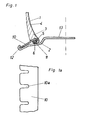
- Figure 1 shows a first embodiment of a vehicle wheel with a tire and a rim radially in partial section.
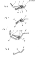
- 1a shows a part of a bead ring which is provided as an anchoring element of the tire on the rim in plan view; 2 to 4 further exemplary embodiments of a vehicle wheel radially in partial section and FIG. 5 a modified rim.
- the vehicle wheel consists essentially of a tire 1, a rigid one-piece rim 2 and two bead rings 10 assigned to the tire 1.
- the tire 1 is provided in a known manner with a belt (not shown) and a single or multi-layer radial carcass 4.
- the free end areas of the radial carcass 4 are turned over in bead areas 5 around bead fillers 6 to be described.
- the roll-up 3 of the carcass 4 ends in the sidewall region of the tire 1.
- each bead ring 10 which is assigned to the bead area 5 and anchored to the bead area 5, is angled pointing in the direction of the tire axis, the bead area 5 being seated in the depression formed by this angling, and thus being carcassed by the radially outwardly bent carcass looped around the bead filler 6 4 is formed.
- Hiebei is provided as a bead filler 6, a core element made of elastomeric material, preferably rubber, with any cross section.
- the turn-over area of the carcass 4 can additionally be filled with cushion elements (cushion rubber).
- the rim 2 adapted to this tire foot has seat surfaces 11 for the bead area 5, each seat surface 11 being inclined at an angle of approximately 2 to 10 ° with respect to the axial direction and being designed as a conically widening surface in the direction of the tire center plane, as a result of which the tire is mounted 1 on the rim 2 is relieved.
- the outer end regions of the rim 2 have edge regions which are flanged radially outwards, as a result of which a latching groove 12 for the bead ring 10 which extends over the rim circumference is formed.
- the area of the bead ring 10 assigned to the locking groove 12 is, as can be seen from FIG. 1 a, provided at regular intervals with incisions 10 a, which are preferably provided every 2 to 5 cm and extending approximately to the center of the bead ring 10. Because the bead rings 10 out incisions 10a enable the tire to be mounted, although they are made of a firm but resilient material, for example stainless spring steel. The incisions 10a widen when the bead ring 10 is pulled over the flanged edge region of the rim 2.
- the tire 1 By anchoring the tire 1 to the rim 2 according to the invention via two bead rings 10, it is ensured that the tire 1 cannot detach itself from the rim 2 even if the tire is defective, that is to say during emergency running.
- the bead rings 10 hold in each case the bead portions 5 on the seating surfaces 1 1 of the rim 2. As the rim 2 requires no deep bed, their outer periphery may be formed as a supporting surface 13 for the tire 1 at emergency.
- the bead rings 10 can be positioned on the tire 1 when the tire 1 is not vulcanized and can be vulcanized with the tire 1, as a result of which there is a firm, non-detachable connection between the tire 1 and the bead rings 10. However, it is also possible to attach the bead rings 10 only to the finished molded and vulcanized tire 1.
- the embodiment shown in Fig. 2 differs from the example shown in Fig- 1 in that the tire sidewall substantially g bauchi it is designed, the lower end portion of the side wall so that almost parallel to the bead ring 10 extends and covers these substantially.
- the individual components are numbered in accordance with the exemplary embodiment according to FIG. 1.
- FIG. 3 Another embodiment of the vehicle wheel according to the invention is shown in FIG. 3. This embodiment also differs only slightly from the previous embodiments.
- the locking groove 12 ' is formed by a double angled end portion of the rim 2 '.
- the areas of the bead ring 10 lying between the incisions 10a are at least partially additionally angled.
- FIG 4 shows an exemplary embodiment in which the seat surfaces 11 'provided on the rim 2' are formed for the bead regions 5 'on the inner circumference of the rim 2' '.
- the bead ring 10 is adapted to this inclination and is otherwise designed as in the exemplary embodiment according to FIGS. 1 and 1a, and is held at one end in the locking groove 12 "formed by the flanged edge region of the rim 2", the rim 2 "forming the Locking groove 12 '' is now bent radially inwards.
- the bead area 5 ' in which the second end area of the bead ring 10' is anchored, is bent by approximately 180 ° with respect to the side wall.
- the rim 2 can be provided with a so-called hump 14 in a manner known per se, the rim hump 14 being able to be provided over the entire circumference of the rim 2 or being only locally worn.
- the locking groove 12, 12 ', 12 can be formed by locking elements (not shown), which are preferably formed from the material of the rim 2, 2', 2 'and, for example, with the rim 2, 2', 2" are welded, interrupted.
- the distance of these locking elements from each other corresponds to the distance of the incisions 10a on the retaining ring 10, the locking elements into the one when the tire is mounted cuts 10a of the retaining ring 10 engage.
- the invention is not restricted to the exemplary embodiments shown. Further modifications are possible without leaving the scope of the scope of protection.
- the individual design variants can be combined with one another.
- the rim can also be made in two parts.
- a tire made of rubber or plastic or of a fiber-reinforced material can be used as the tire.
- the tire can be both a radial tire with a belt and a diagonal tire.
- metal will in particular be used for the retaining ring.
Landscapes
- Engineering & Computer Science (AREA)
- Mechanical Engineering (AREA)
- Arrangement Or Mounting Of Propulsion Units For Vehicles (AREA)
- Vehicle Body Suspensions (AREA)
- Tires In General (AREA)
Applications Claiming Priority (2)
| Application Number | Priority Date | Filing Date | Title |
|---|---|---|---|
| AT1758/84 | 1984-05-28 | ||
| AT0175884A AT381070B (de) | 1984-05-28 | 1984-05-28 | Fahrzeugrad |
Publications (3)
| Publication Number | Publication Date |
|---|---|
| EP0163625A2 true EP0163625A2 (fr) | 1985-12-04 |
| EP0163625A3 EP0163625A3 (en) | 1987-05-20 |
| EP0163625B1 EP0163625B1 (fr) | 1988-11-02 |
Family
ID=3520363
Family Applications (1)
| Application Number | Title | Priority Date | Filing Date |
|---|---|---|---|
| EP85890095A Expired EP0163625B1 (fr) | 1984-05-28 | 1985-04-18 | Roue de véhicule |
Country Status (4)
| Country | Link |
|---|---|
| US (1) | US4745958A (fr) |
| EP (1) | EP0163625B1 (fr) |
| AT (2) | AT381070B (fr) |
| DE (1) | DE3565958D1 (fr) |
Cited By (3)
| Publication number | Priority date | Publication date | Assignee | Title |
|---|---|---|---|---|
| DE3942286A1 (de) * | 1989-12-21 | 1991-06-27 | Klaus D Dipl Ing Debus | Virtuelle felgenverbreiterung bei innen montierten reifensystemen |
| EP0449670A3 (en) * | 1990-03-30 | 1992-09-30 | Sumitomo Rubber Industries Limited | Tyre and rim |
| US5242000A (en) * | 1990-03-30 | 1993-09-07 | Sumitomo Rubber Industries, Ltd. | Combined bead portion and rim arrangement for tire |
Families Citing this family (1)
| Publication number | Priority date | Publication date | Assignee | Title |
|---|---|---|---|---|
| US20060005903A1 (en) * | 2004-07-08 | 2006-01-12 | Fry Timothy L | Non-pneumatic wheel |
Family Cites Families (10)
| Publication number | Priority date | Publication date | Assignee | Title |
|---|---|---|---|---|
| US1932191A (en) * | 1931-01-27 | 1933-10-24 | Alvin H Shoemaker | Pneumatic tire and rim |
| CH271817A (de) * | 1949-03-25 | 1950-11-15 | Fischer Ag Georg | Radfelge mit Pneumatikreifen. |
| DE877262C (de) * | 1950-08-18 | 1953-05-21 | Wingfoot Corp | Abnehmbarer Reifenhalter fuer Draht- und Wulstreifen |
| IT1044843B (it) * | 1972-05-31 | 1980-04-21 | Pirelli | Pneumatico per ruote di veicoli |
| IT959778B (it) * | 1972-05-31 | 1973-11-10 | Pirelli | Metodo per bloccare una copertura pneumatica al cerchio e ruota pneumatica cosi ottenuta |
| GB1438688A (en) * | 1973-07-26 | 1976-06-09 | Clark C W | Vehicle wheels |
| JPS5279405A (en) * | 1975-12-25 | 1977-07-04 | Sumitomo Rubber Ind | Pneumatic tire for motor cycle |
| US4169496A (en) * | 1977-10-31 | 1979-10-02 | General Motors Corporation | Run-flat tire and wheel arrangement with inverted bead interlock |
| DE3231012A1 (de) * | 1982-08-20 | 1984-02-23 | Continental Gummi-Werke Ag, 3000 Hannover | Fahrzeugrad |
| DE3407968A1 (de) * | 1984-03-03 | 1985-09-12 | Jonny 4000 Düsseldorf Janus | Radialreifen |
-
1984
- 1984-05-28 AT AT0175884A patent/AT381070B/de not_active IP Right Cessation
-
1985
- 1985-04-18 DE DE8585890095T patent/DE3565958D1/de not_active Expired
- 1985-04-18 EP EP85890095A patent/EP0163625B1/fr not_active Expired
- 1985-04-18 AT AT85890095T patent/ATE38356T1/de not_active IP Right Cessation
- 1985-05-13 US US06/733,461 patent/US4745958A/en not_active Expired - Fee Related
Cited By (3)
| Publication number | Priority date | Publication date | Assignee | Title |
|---|---|---|---|---|
| DE3942286A1 (de) * | 1989-12-21 | 1991-06-27 | Klaus D Dipl Ing Debus | Virtuelle felgenverbreiterung bei innen montierten reifensystemen |
| EP0449670A3 (en) * | 1990-03-30 | 1992-09-30 | Sumitomo Rubber Industries Limited | Tyre and rim |
| US5242000A (en) * | 1990-03-30 | 1993-09-07 | Sumitomo Rubber Industries, Ltd. | Combined bead portion and rim arrangement for tire |
Also Published As
| Publication number | Publication date |
|---|---|
| EP0163625A3 (en) | 1987-05-20 |
| ATE38356T1 (de) | 1988-11-15 |
| DE3565958D1 (en) | 1988-12-08 |
| ATA175884A (de) | 1986-01-15 |
| EP0163625B1 (fr) | 1988-11-02 |
| US4745958A (en) | 1988-05-24 |
| AT381070B (de) | 1986-08-25 |
Similar Documents
| Publication | Publication Date | Title |
|---|---|---|
| EP0110023B1 (fr) | Anneau d'obturation pour roue de véhicule | |
| DE19707090A1 (de) | Luftbereiftes Fahrzeugrad | |
| WO1999019158A2 (fr) | Roue de vehicule avec corps d'appui de secours | |
| DE2653658A1 (de) | Fahrzeugluftreifen mit plattfahreigenschaften | |
| EP0156009B1 (fr) | Roue de véhicule automobile | |
| DE3111566A1 (de) | Luftreifenanordnung | |
| EP0163625B1 (fr) | Roue de véhicule | |
| EP0125640B1 (fr) | Bandages pleins pour roue de véhicules | |
| EP0111118A1 (fr) | Roue de véhicule | |
| DE3704830A1 (de) | Fahrzeugrad | |
| DE1176013B (de) | Spreiz- und Abstuetzring fuer schlauchlose Reifen | |
| DE19811541A1 (de) | Fahrzeugrad mit - insbesondere einteiliger - Felge und schlauchlosem Luftreifen, das für Notlauf geeignet ist und ein Verfahren zur Montage eines Luftreifens auf einer Felge mit Notlaufstützfläche | |
| DE3405970C2 (fr) | ||
| DE3804505A1 (de) | Luftbereiftes fahrzeugrad | |
| DE3408402C2 (fr) | ||
| DE2937271A1 (de) | Luftreifen-radfelgenanordnung | |
| DE19837712A1 (de) | Fahrzeugrad | |
| DE3531177A1 (de) | Luftbereiftes fahrzeugrad | |
| EP0153295B1 (fr) | Bandage pneumatique pour roue de véhicules | |
| DE2937272A1 (de) | Luftreifen-radfelgenanordnung | |
| EP1900550A1 (fr) | Appui de soutien segmente avec moyens de serrage | |
| DE19927336C2 (de) | Fahrzeugrad Felge und schlauchlosem Luftreifen, das für Notlauf geeignet ist | |
| DE3402811A1 (de) | Fahrzeugrad | |
| DE19927335C2 (de) | Fahrzeugrad mit Felge und schlauchlosem Luftreifen, das für Notlauf geeignet ist | |
| DE3505386A1 (de) | Fahrzeugrad |
Legal Events
| Date | Code | Title | Description |
|---|---|---|---|
| PUAI | Public reference made under article 153(3) epc to a published international application that has entered the european phase |
Free format text: ORIGINAL CODE: 0009012 |
|
| AK | Designated contracting states |
Designated state(s): AT DE FR GB IT |
|
| RAP1 | Party data changed (applicant data changed or rights of an application transferred) |
Owner name: SEMPERIT REIFEN AKTIENGESELLSCHAFT |
|
| RAP1 | Party data changed (applicant data changed or rights of an application transferred) |
Owner name: SEMPERIT REIFEN AKTIENGESELLSCHAFT |
|
| PUAL | Search report despatched |
Free format text: ORIGINAL CODE: 0009013 |
|
| AK | Designated contracting states |
Kind code of ref document: A3 Designated state(s): AT DE FR GB IT |
|
| 17P | Request for examination filed |
Effective date: 19870427 |
|
| 17Q | First examination report despatched |
Effective date: 19871026 |
|
| GRAA | (expected) grant |
Free format text: ORIGINAL CODE: 0009210 |
|
| AK | Designated contracting states |
Kind code of ref document: B1 Designated state(s): AT DE FR GB IT |
|
| REF | Corresponds to: |
Ref document number: 38356 Country of ref document: AT Date of ref document: 19881115 Kind code of ref document: T |
|
| REF | Corresponds to: |
Ref document number: 3565958 Country of ref document: DE Date of ref document: 19881208 |
|
| GBT | Gb: translation of ep patent filed (gb section 77(6)(a)/1977) | ||
| ITF | It: translation for a ep patent filed | ||
| ET | Fr: translation filed | ||
| PLBE | No opposition filed within time limit |
Free format text: ORIGINAL CODE: 0009261 |
|
| STAA | Information on the status of an ep patent application or granted ep patent |
Free format text: STATUS: NO OPPOSITION FILED WITHIN TIME LIMIT |
|
| 26N | No opposition filed | ||
| ITTA | It: last paid annual fee | ||
| PGFP | Annual fee paid to national office [announced via postgrant information from national office to epo] |
Ref country code: GB Payment date: 19930309 Year of fee payment: 9 |
|
| PGFP | Annual fee paid to national office [announced via postgrant information from national office to epo] |
Ref country code: FR Payment date: 19930315 Year of fee payment: 9 |
|
| PGFP | Annual fee paid to national office [announced via postgrant information from national office to epo] |
Ref country code: AT Payment date: 19930406 Year of fee payment: 9 |
|
| PGFP | Annual fee paid to national office [announced via postgrant information from national office to epo] |
Ref country code: DE Payment date: 19930427 Year of fee payment: 9 |
|
| PG25 | Lapsed in a contracting state [announced via postgrant information from national office to epo] |
Ref country code: GB Effective date: 19940418 Ref country code: AT Effective date: 19940418 |
|
| GBPC | Gb: european patent ceased through non-payment of renewal fee |
Effective date: 19940418 |
|
| PG25 | Lapsed in a contracting state [announced via postgrant information from national office to epo] |
Ref country code: FR Effective date: 19941229 |
|
| PG25 | Lapsed in a contracting state [announced via postgrant information from national office to epo] |
Ref country code: DE Effective date: 19950103 |
|
| REG | Reference to a national code |
Ref country code: FR Ref legal event code: ST |