EP0163741A1 - Farbkathodenstrahlröhre mit strahlindizierung - Google Patents
Farbkathodenstrahlröhre mit strahlindizierung Download PDFInfo
- Publication number
- EP0163741A1 EP0163741A1 EP84904166A EP84904166A EP0163741A1 EP 0163741 A1 EP0163741 A1 EP 0163741A1 EP 84904166 A EP84904166 A EP 84904166A EP 84904166 A EP84904166 A EP 84904166A EP 0163741 A1 EP0163741 A1 EP 0163741A1
- Authority
- EP
- European Patent Office
- Prior art keywords
- stripes
- electron beam
- ray tube
- phosphor
- electrode
- Prior art date
- Legal status (The legal status is an assumption and is not a legal conclusion. Google has not performed a legal analysis and makes no representation as to the accuracy of the status listed.)
- Granted
Links
Images


Classifications
-
- H—ELECTRICITY
- H01—ELECTRIC ELEMENTS
- H01J—ELECTRIC DISCHARGE TUBES OR DISCHARGE LAMPS
- H01J29/00—Details of cathode-ray tubes or of electron-beam tubes of the types covered by group H01J31/00
- H01J29/02—Electrodes; Screens; Mounting, supporting, spacing or insulating thereof
- H01J29/10—Screens on or from which an image or pattern is formed, picked up, converted or stored
- H01J29/18—Luminescent screens
- H01J29/30—Luminescent screens with luminescent material discontinuously arranged, e.g. in dots, in lines
- H01J29/32—Luminescent screens with luminescent material discontinuously arranged, e.g. in dots, in lines with adjacent dots or lines of different luminescent material, e.g. for colour television
- H01J29/327—Black matrix materials
-
- B—PERFORMING OPERATIONS; TRANSPORTING
- B82—NANOTECHNOLOGY
- B82Y—SPECIFIC USES OR APPLICATIONS OF NANOSTRUCTURES; MEASUREMENT OR ANALYSIS OF NANOSTRUCTURES; MANUFACTURE OR TREATMENT OF NANOSTRUCTURES
- B82Y10/00—Nanotechnology for information processing, storage or transmission, e.g. quantum computing or single electron logic
-
- H—ELECTRICITY
- H01—ELECTRIC ELEMENTS
- H01J—ELECTRIC DISCHARGE TUBES OR DISCHARGE LAMPS
- H01J29/00—Details of cathode-ray tubes or of electron-beam tubes of the types covered by group H01J31/00
- H01J29/02—Electrodes; Screens; Mounting, supporting, spacing or insulating thereof
- H01J29/10—Screens on or from which an image or pattern is formed, picked up, converted or stored
- H01J29/18—Luminescent screens
- H01J29/34—Luminescent screens provided with permanent marks or references
-
- H—ELECTRICITY
- H01—ELECTRIC ELEMENTS
- H01J—ELECTRIC DISCHARGE TUBES OR DISCHARGE LAMPS
- H01J31/00—Cathode ray tubes; Electron beam tubes
- H01J31/08—Cathode ray tubes; Electron beam tubes having a screen on or from which an image or pattern is formed, picked up, converted, or stored
- H01J31/10—Image or pattern display tubes, i.e. having electrical input and optical output; Flying-spot tubes for scanning purposes
- H01J31/12—Image or pattern display tubes, i.e. having electrical input and optical output; Flying-spot tubes for scanning purposes with luminescent screen
- H01J31/123—Flat display tubes
- H01J31/124—Flat display tubes using electron beam scanning
-
- H—ELECTRICITY
- H04—ELECTRIC COMMUNICATION TECHNIQUE
- H04N—PICTORIAL COMMUNICATION, e.g. TELEVISION
- H04N9/00—Details of colour television systems
- H04N9/12—Picture reproducers
- H04N9/16—Picture reproducers using cathode ray tubes
- H04N9/22—Picture reproducers using cathode ray tubes using the same beam for more than one primary colour information
- H04N9/24—Picture reproducers using cathode ray tubes using the same beam for more than one primary colour information using means, integral with, or external to, the tube, for producing signal indicating instantaneous beam position
-
- H—ELECTRICITY
- H01—ELECTRIC ELEMENTS
- H01J—ELECTRIC DISCHARGE TUBES OR DISCHARGE LAMPS
- H01J2231/00—Cathode ray tubes or electron beam tubes
- H01J2231/12—CRTs having luminescent screens
- H01J2231/121—Means for indicating the position of the beam, e.g. beam indexing
Definitions
- This invention relates to a beam index type color cathode ray tube using an index electrode stripe.
- a black and white cathode ray tube in which a phosphor screen is formed on a panel of a tube envelope, the phosphor screen is scanned by a single electron beam emitted from an electron gun and a picture formed on the phosphor screen is observed from the side at which the electron beam impinges. Since this cathode ray tube can be made flat on the whole, it is very suitable for use as a flat and small-sized television receiver.
- cathode ray tube when such cathode ray tube is formed as a color cathode ray tube, such cathode ray tube is so arranged as to enable the viewer to see the picture formed on the phosphor screen from the side in which the electron beam enters so that it can not adopt a color selecting electrode such as a shadow mask, an aperture grille and so on.
- the beam index type color cathode ray tube is classified into two systems by the difference between one arrangement of a phosphor stripe and an index stripe for the scanning direction of the electron beam (single electron beam).
- the phosphor stripe and the index stripe are aligned in the direction same as the electron beam scanning direction, while in the second system, they are alinged in the direction perpendicular to the electron beam scanning direction.
- the beam index type color cathode ray tube of the first system is high in resolution, it has a defect that a time division frequency for use in time division-modulating the electron beam by the respective primary color signals is high.
- the beam index type color cathode ray tube of the second system is low in resolution but has an advantage that the time division frequency to be used for time division-modulating the electron beam by the respective primary color signals becomes low.
- the beam index type color cathode ray tube is further divided into another two types by the . arrangement of the index stripe.
- the color cathode ray tubes of beam index type using a phosphor stripe and an electrode stripe as their index stripes.
- the beam index type color cathode ray tube using the index phosphor stripe it is requested to provide a plurality of photodetectors outside the tube envelope to detect the light emitted from the index phosphor stripe so that the arrangement thereof becomes complicated and that the precision for detecting the electron beam landing position is lower. Further, it is difficult for this beam index type color cathode ray tube to match the mutual positions of each color phosphor stripe and index phosphor stripe with each other.
- the photodetector is not required and thus the arrangement thereof is simplified. Further, the accuracy in the detection of the electrode landing position is high and it is not so difficult for this beam index type color cathode ray tube to match the mutual positions of the respectibe color phosphor stripes and the index electrode stripe. Further, in a beam index type color cathode ray tube of a type in which a picture formed on the phosphor screen is viewed from the side opposite to the side at which-the electron beam impinges thereon, an electrostatic capacity between the index electrode stripe and the metal back film becomes a serious problem so that the amount of an electron landing position detecting signal from the index electrode stripe is lowered.
- the index electrode stripe and the metal back film are difficult to be produced.
- the index electrode in order to make the index electrode apart from the metal back film the index electrode must be formed on an insulating material on the metal back film or a carbon layer for preventing a color blur. from being produced between the phosphor stripes. Thus, it is difficult to form the side edge of the index electrode stripe sharp.
- a beam index type color cathode ray tube which has no color blur, is simple in construction, has a low time division frequency for use in time division-modulating the electron beam (single electron beam) by the respective color signals and which is high in accuracy in detecting the electron beam landing position, enough in the amount of the detecting signal and easy in matching the mutual positions of the index electrode stripe and the color phosphor stripes of respective colors.
- the phosphor screen is formed of a plurality of color phosphor stripes, which are so formed on a panel that each of which is extended in the line scanning direction by the single electron beam and which are repeatedly arranged in turn in the direction perpendicular to the line scanning direction, and first and second index electrode stripes having light absorbing property formed on the panel which are arranged alternately between the adjacent phosphor stripes and there is provided an auxiliary vertical deflecting means.
- the phosphor stripes and the first and second index electrode stripes at the both sides thereof are scanned by the single electron beam simultaneously and a difference signal between the first and second electron beam landing position detecting signals from the first and second index electrode stripes is supplied to the auxiliary vertical deflecting means as a vertical correction deflecting signal whereby the scanning tracking of the single electron beam relative to the phosphor stripe is controlled by the auxiliary vertical deflecting means.
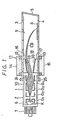
- Fig. 1 is a side cross-sectional view of ⁇ an embodiment of the color cathode ray tube according to the present invention
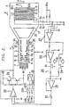
- Fig. 2 is a plan cross-sectional view of the color cathode ray tube of Fig. 1 from which an upper panel is removed and a circuit diagram showing a peripheral circuit thereof
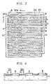
- Figs. 3 and 4 are respectively a plan view and a cross-sectional view showing the phosphor screen of the color cathode ray tube shown in Fig. 1
- Figs. 5A to 5J are respectively cross-sectional views illustrating manufacturing processes of a method for making the phosphor screen of the color cathode ray tube of Fig. 1.
- Reference numeral 1 designates an overall of a beam index type color cathode ray tube made as a flat tube.
- Reference numeral 2 designates the whole of a glass tube envelope which consists of an upper panel 3 and a lower panel 4 which are in parallel to each other, a side plate 5 provided between the upper panel and the lower panel and a neck portion 6.
- Reference numeral 7 designates a pin formed on the free end of the neck portion 6.
- Reference numeral 8 designates a phosphor screen formed on the inner surface of the lower panel 4 and 9 an opposing electrode made of a transparent electrode formed on the inner surface of the upper panel 3. This opposing electrode is provided in opposing relation to the phosphor screen 8.
- the phosphor screen 8 is formed of primary color phosphors, or red, green and blue phosphors R, G and B which are formed on the inner surface of the lower panel 4 so as to extend in the line scanning direction x of a single electron beam EB and arranged repeatedly in turn in the direction (field scanning direction) y perpendicular to the line scanning direction x and is formed of first and second index electrode stripes ID 1 and ID 2 which have light absorbing property are insulated with one another and are formed on the inner surface of the lower panel 4 so as to be arranged alternately between the adjoining phosphor stripes R, G and B.
- the index stripe electrodes ID 1 and ID 2 are also arranged at the outside of each of the phosphor stripes formed on the both ends in the direction y.
- the first and second index electrode stripes ID 1 and ID 2 are of a double layer structure which consists of an aluminium conductive stripe a formed on the inner surface of the lower panel 4 and a light absorbing stripe b made of carbon formed thereon to prevent the color blur from being produced.
- Reference letters L 1 and L 2 respectively designate coupling electrodes which connect the first and second index stripes ID 1 and ID 2 separately. Also it is possible to form a light absorbing stripe by oxidizing the surface of the conductive stripe a made of aluminium.
- the single electron beam EB simultaneously scan, as shown in Fig. 3, the phosphor stripe R, G or B and the first and second index electrode stripes ID 1 and ID 2 formed at both sides of each of the phosphor stripes.
- SPe and SPo respectively designate electron beam spots formed in the scanning of even and odd fields. It is assumed that upon scanning the even field, the electron beam scans the phosphor stripes R, B, G, R, B, ... sequentially. it scans the phosphor stripes G, R, B, G, R, B, ... sequentially upon the odd field, thus an interlaced scanning being carried out. It is sufficient that the number of the phosphor stripes may be about 483 in an effective picture screen.
- a voltage of, for example, 8.4 kV is applied to the first and second index electrodes ID 1 and ID 2 and a voltage of, for example, 5.0 kV is applied to the opposing electrode 9 to thereby deflect (secondary deflection) the electron beam EB emitted from an electron gun 10 which will be described below so that the electron beam is made incident on the phosphor screen 8.
- Reference numeral 10 designates an electron gun which is housed in the neck portion 6.
- This electron gun 10 comprises a cathode K, a first grid G 1 , a second grid G 2 , a third grid (focussing electrode) G 3 and a fourth grid G 4 .
- the third and fourth grids G 3 and G 4 constitute a main lens and carry out the dynamic focussing of the electron beam EB.
- Reference numeral 11 designates a horizontal deflection yoke which consists of upper and lower ferrite cores 14 and 15 on which horizontal deflection coils 12 and 13 are respectively wound and which are located outside the neck portion 6 and upper and lower ferrite magnetic poles 16 and 17 which are respectively mounted inside the neck portion 6.
- Reference numeral 18 designates a vertical deflection plate which is formed of opposing electrode plates 19 and 20 which are respectively coated on the above magnetic poles 16 and 17.
- the electron beam EB from the electron gun 10 is horizontally deflected by the horizontal deflection yoke 11 and deflected vertically by the vertical deflection plate 18. These are primary deflection. Thereafter, it is deflected secondarily by the first and second index stripes ID 1 and ID 2 and the opposing electrode 9 so as to scan the respective primary color phosphor stripes R, G and B of the phosphor screen 8 in the interlaced scanning fashion as described above.
- Red, green and blue signals through red, green and blue signal input terminals 21R, 21G and 21B are respectively supplied to an amplifier 23 through on-off switches 22R, 22G and 22B one of which is turned on at every horizontal cycle. Then, the line sequential signal of red, blue, green, red, blue, green, ... from the amplifier 23 is supplied to the cathode K (or the first grid G 1 ) of the electron gun 10.
- Reference numerals 24 and 25 respectively designate a pair of auxiliary vertical deflection coils which are connected with each other to control the scanning tracking of the electron beam EB for the respective phosphor stripes R, G and B.
- the auxiliary vertical deflection coils are located on the outer periphery of the neck portion 6 and nearer to the side of the electron gun 10 than the vertical deflection plate 18. It is possible that the function of the auxiliary vertical deflection coils 24 and 25 is carried out by the vertical deflection plate 18 or they may be replaced by an auxiliary electrostatic deflection plate.
- circuit 26 which is supplied with the differential signal of first and second electron beam landing position detecting signals S 1 and S 2 from the first and second index electrode stripes ID 1 and ID 2 to thereby produce a vertical correcting deflection signal which is to be supplied to the above auxiliary vertical deflection coils 24 and 25.
- Reference letters T 1 and T 2 respectively designate terminals which are led out from the first and second index electrode stripes ID 1 and ID 2 through the coupling electrodes L 1 and L 2 .
- the terminals Ti and T 2 are supplied with the above-described high voltage of 8.4 kV from a power source +B H through resistors.
- the first and second electron beam landing position detecting signals (A.C. components) S 1 and S 2 derived from the terminals T 1 and T 2 are supplied through capacitors to a differential amplifier 27 which operates as a subtracter.
- the differential output from the differential amplifier 27 is supplied through a semiconductor switch 28 formed of an FET to an amplifier 29 and also through a series circuit of an inverted amplifier 30 and a semiconductor switch 31 formed of an FET to the amplifier 29.
- the semiconductor switches 28 and 31 are alternately turned on and off at every vertical period in synchronism with the vertical synchronizing signal.
- the output from the amplifier 29 is supplied through a level adjuster 32 to a driving amplifier 33.
- As the amplifiers 27, 29, 30 and 33 there are used operational amplifiers, respectively.
- the output from the driving amplifier 33 is supplied to an output amplifier 34 which is formed of an SEPP circiut. Then, a vertical correcting deflection signal produced at an output terminal T 3 thereof is supplied to one terminal of the auxiliary vertical deflecting coil 24 and the other end of the auxiliary vertical deflecting coil 25 is grounded through a resistor.
- the electron beam EB scans the respective phosphor stripes R, G or B of the phosphor screen 8 together with the first and second index electrode stripes ID 1 and ID 2 formed at both sides of the phosphor stripe.
- the D.C..components thereof are flowed to the cathode K and only the A.C. components thereof are derived and then fed to the differential amplifier 27. Then, if the scanning position is displaced from the center thereof to either of the positive and negative directions in the direction y, the differential amplifier 27 produces either positive output or negative output in response thereto.
- This output is supplied to the auxiliary vertical deflection coils 24 and 25, and the vertical scanning position of the electron beam EB is controlled by its auxiliary vertical deflecting magnetic field so that the electron beam scans the center of the phosphor stripes R, G or B.
- the semiconductor switches 28 and 31 are turned on and off to therby change over the polarity of the vertical correcting deflection signal which is supplied to the auxiliary vertical deflecting coils 24 and 25 in the scanning of odd or even field.
- a manufacturing method for producing the phosphor screen 8 will be described in the order of manufacturing processes.
- a conductive layer 40 is formed on the whole surface of the lower panel 4 by the vacuum evaporation of aluminium. Then, a first photosensitive resinous layer 41 is deposited on the whole surface of the conductive layer and ultraviolet rays are made incident on the photosensitive resinous layer 41 through a mask whereby the photosensitive resinous layer is partially cured (Fig. 5A).
- the conductive layer 40 is etched away and the cured portion 41' of the photosensitive resinous layer 41 remaining on the non-removed portion 40' of the conductive layer 40 is removed, a conductive stripe 40' (a) corresponding to the first and second index electrode- stripes ID 1 and ID 2 and the both coupling electrodes L i and L 2 is formed on the lower panel 4 (Fig. 5C).
- a second photosensitive resinous layer 43 is deposited on the whole surface of the lower panel 4 and the conductive stripe 40' (a) and by using the conductive stripe 40' (a) itself as a mask, the ultraviolet light rays are made incident on the photosensitive resinous layer 43 from the backside of the lower panel 4 to partially cure the photosensitive resinous layer (Fig. 5D).
- the non-cured portion of the photosensitive resinous layer 43 formed on the conductive stripe 40' (a) is removed by the development by which a cured portion 43' is left between the adjacent conductive stripes 40' (a) (Fig. 5E).
- a carbon layer 44 is coated on the whole surface of the conductive stripe 40' (a) and the cured portion 43' of the photosensitive resinous layer 43 (Fig. 5F).
- the first and second index electrode stripes ID 1 and ID 2 each of which is made of the conductive stripe 40' (a) and the carbon stripe 44 1 (b) thereon and the coupling electrodes L 1 and L 2 (not shown) are formed respectively (Fig. 5G).
- a red phosphor layer 45 containing photosensitive resin (Fig. 5H).
- the ultraviolet rays are made incident on the red phosphor layer 45 from the underside of the lower panel 4 to cure a portion of the red phosphor layer 45 between the first and second index electrode stripes ID 1 and ID 2 which is to form, for example, the red phosphor stripe.
- the non-cured portion is removed by the development to thereby form a red phosphor stripe 45' (R) between the first and second index electrode stripes ID 1 and ID 2 (Fig. 51).
- the above-mentioned beam index type color cathode ray tube has the following advantages. Since the first and second index electrode stripes ID 1 and ID 2 having light absorbing property are respectively provided between the adjoining phosphor stripes of R, G and B, it is free of the color blur. Since the phosphor stripes R, G and B and the first and second index electrode stripes ID 1 and ID 2 are provided in the direction perpendicular to the electron beam scanning direction, the beam index type color cathode ray tube is simplified in construction and the time division frequency for use in time division-modulating the single electron beam becomes low.
- the single electron beam scans three of them simultaneously to thereby produce the first and second electron beam landing position detecting signals and the difference signal therebetween is used as the vertical correcting deflecting signal, the electron beam landing position detecting signal is high in accuracy. Since no metal back film is used for the phosphor screen 8, the first and second electron beam landing position detecting signals from the first and second index electrode stripes ID 1 and ID 2 are enough in amount.
- the carbon layer b on the first and second index electrode stripes ID 1 and ID 2 is formed by using the conductive layer a therebeneath as the mask, the carbon layer b is formed easily and is high in positioning accuracy relative to the conductive layer a and the positioning is made easy. Since the phosphor stripes R, G and B are formed by using the first and second index electrode stripes ID 1 and ID 2 as the mask, the edges of the phosphor stripes R, G and B can be formed sharp, the positioning thereamong can be made with ease and in addition, the mask for selecting the phosphor stripes R, G and B can be formed roughly. Furthermore, since the exposure for use in forming the phosphor stripes R, G and B containing the photosensitive resin is carried out from the backside of the lower panel 4, it becomes possible to increase the strength for bonding the phosphor stripes R, G and B to the lower panel.
- the cathode ray tube in which the phosphor screen is formed on the panel thereof and is scanned by the single electron beam from the electron gun and the picture formed on the phosphor screen can be observed from the side at which the electron beam is made incident, there is provided the beam index type color cathode ray tube having no color blur, the simplified arrangement, the low time division frequency for use in time division-modulating the electron beam (single electron beam) by the respective primary color signals and which is high in accuracy for detecting the electron beam landing position, enough in the amount of the detecting signal and easy in matching the positions of the index electrode stripes and the respective phosphor stripes.
Landscapes
- Engineering & Computer Science (AREA)
- Chemical & Material Sciences (AREA)
- Nanotechnology (AREA)
- Multimedia (AREA)
- Signal Processing (AREA)
- Physics & Mathematics (AREA)
- Mathematical Physics (AREA)
- Theoretical Computer Science (AREA)
- Crystallography & Structural Chemistry (AREA)
- Cathode-Ray Tubes And Fluorescent Screens For Display (AREA)
- Video Image Reproduction Devices For Color Tv Systems (AREA)
- Details Of Television Scanning (AREA)
Applications Claiming Priority (2)
| Application Number | Priority Date | Filing Date | Title |
|---|---|---|---|
| JP21218183A JPS60105145A (ja) | 1983-11-11 | 1983-11-11 | ビ−ムインデツクス式カラ−陰極線管 |
| JP212181/83 | 1983-11-11 |
Publications (3)
| Publication Number | Publication Date |
|---|---|
| EP0163741A1 true EP0163741A1 (de) | 1985-12-11 |
| EP0163741A4 EP0163741A4 (de) | 1986-04-02 |
| EP0163741B1 EP0163741B1 (de) | 1989-07-19 |
Family
ID=16618253
Family Applications (1)
| Application Number | Title | Priority Date | Filing Date |
|---|---|---|---|
| EP19840904166 Expired EP0163741B1 (de) | 1983-11-11 | 1984-11-12 | Farbkathodenstrahlröhre mit strahlindizierung |
Country Status (4)
| Country | Link |
|---|---|
| EP (1) | EP0163741B1 (de) |
| JP (1) | JPS60105145A (de) |
| DE (1) | DE3479076D1 (de) |
| WO (1) | WO1985002313A1 (de) |
Cited By (3)
| Publication number | Priority date | Publication date | Assignee | Title |
|---|---|---|---|---|
| WO2000038212A1 (en) * | 1998-12-21 | 2000-06-29 | Koninklijke Philips Electronics N.V. | Cathode ray tube of the index type |
| WO2002093613A3 (en) * | 2001-05-17 | 2003-03-13 | Koninkl Philips Electronics Nv | Tracking picture tube |
| WO2002093612A3 (en) * | 2001-05-17 | 2003-03-13 | Koninkl Philips Electronics Nv | Tracking picture tube |
Families Citing this family (1)
| Publication number | Priority date | Publication date | Assignee | Title |
|---|---|---|---|---|
| KR890002965B1 (ko) * | 1986-12-01 | 1989-08-14 | 재단법인 한국화학연구소 | 고순도 반도체 규소박판을 이용한 고순도 반도체 재료인 규소의 제조방법 및 장치 |
Family Cites Families (4)
| Publication number | Priority date | Publication date | Assignee | Title |
|---|---|---|---|---|
| DE1136368B (de) * | 1960-09-30 | 1962-09-13 | Siemens Ag | Anordnung zur Wiedergabe von Farbfernsehbildern mit einer Indexkathodenstrahlroehre |
| JPS4814856B1 (de) * | 1968-05-23 | 1973-05-10 | ||
| JPS5197926A (de) * | 1975-02-25 | 1976-08-28 | ||
| JPS5949087A (ja) * | 1982-09-13 | 1984-03-21 | Sony Corp | テレビジヨン受像機 |
-
1983
- 1983-11-11 JP JP21218183A patent/JPS60105145A/ja active Pending
-
1984
- 1984-11-12 DE DE8484904166T patent/DE3479076D1/de not_active Expired
- 1984-11-12 EP EP19840904166 patent/EP0163741B1/de not_active Expired
- 1984-11-12 WO PCT/JP1984/000542 patent/WO1985002313A1/ja not_active Ceased
Cited By (3)
| Publication number | Priority date | Publication date | Assignee | Title |
|---|---|---|---|---|
| WO2000038212A1 (en) * | 1998-12-21 | 2000-06-29 | Koninklijke Philips Electronics N.V. | Cathode ray tube of the index type |
| WO2002093613A3 (en) * | 2001-05-17 | 2003-03-13 | Koninkl Philips Electronics Nv | Tracking picture tube |
| WO2002093612A3 (en) * | 2001-05-17 | 2003-03-13 | Koninkl Philips Electronics Nv | Tracking picture tube |
Also Published As
| Publication number | Publication date |
|---|---|
| JPS60105145A (ja) | 1985-06-10 |
| EP0163741B1 (de) | 1989-07-19 |
| WO1985002313A1 (fr) | 1985-05-23 |
| DE3479076D1 (en) | 1989-08-24 |
| EP0163741A4 (de) | 1986-04-02 |
Similar Documents
| Publication | Publication Date | Title |
|---|---|---|
| US2532511A (en) | Television | |
| US2728025A (en) | Post-deflected cathode-ray tubes | |
| US2577038A (en) | Television color picture tube | |
| Law | A three-gun shadow-mask color kinescope | |
| KR900001505B1 (ko) | 컬러 수상장치 | |
| US4059781A (en) | Shadow mask each aperture of which is defined by a quadrupolar lens | |
| US2711493A (en) | Direct-view color tube | |
| US2690517A (en) | Plural beam electron gun | |
| EP0241087A2 (de) | Fernsehprojektionssystem | |
| US3067349A (en) | Method for producing registered color screen cathode-ray tubes | |
| EP0181463A1 (de) | Flache Farbbildkathodenstrahlröhre | |
| EP0163741B1 (de) | Farbkathodenstrahlröhre mit strahlindizierung | |
| US5361020A (en) | Methods and apparatus for improving cathode ray tube image quality | |
| US3772552A (en) | Image pickup tube | |
| US2734146A (en) | noskowicz | |
| GB2059144A (en) | Colour display crt | |
| KR900002905B1 (ko) | 칼라수상관장치 | |
| US3603839A (en) | Color television picture tube of the single electron gun type | |
| US4514756A (en) | Single beam color CRT | |
| USRE25082E (en) | Color kinescopes | |
| US2745035A (en) | Color television tube target structure | |
| US3437868A (en) | Electron gun device | |
| US2739260A (en) | Cathode-ray tube for color television | |
| US3571643A (en) | Plural beam electron gun for a color picture tube with different-sized control grid apertures | |
| US2936399A (en) | Color structure for cathode-ray tubes designed for polychrome image reproduction |
Legal Events
| Date | Code | Title | Description |
|---|---|---|---|
| PUAI | Public reference made under article 153(3) epc to a published international application that has entered the european phase |
Free format text: ORIGINAL CODE: 0009012 |
|
| 17P | Request for examination filed |
Effective date: 19850801 |
|
| AK | Designated contracting states |
Designated state(s): DE FR GB |
|
| A4 | Supplementary search report drawn up and despatched |
Effective date: 19860402 |
|
| 17Q | First examination report despatched |
Effective date: 19880525 |
|
| GRAA | (expected) grant |
Free format text: ORIGINAL CODE: 0009210 |
|
| AK | Designated contracting states |
Kind code of ref document: B1 Designated state(s): DE FR GB |
|
| PG25 | Lapsed in a contracting state [announced via postgrant information from national office to epo] |
Ref country code: FR Free format text: THE PATENT HAS BEEN ANNULLED BY A DECISION OF A NATIONAL AUTHORITY Effective date: 19890719 |
|
| REF | Corresponds to: |
Ref document number: 3479076 Country of ref document: DE Date of ref document: 19890824 |
|
| PG25 | Lapsed in a contracting state [announced via postgrant information from national office to epo] |
Ref country code: GB Effective date: 19891112 |
|
| EN | Fr: translation not filed | ||
| PLBE | No opposition filed within time limit |
Free format text: ORIGINAL CODE: 0009261 |
|
| STAA | Information on the status of an ep patent application or granted ep patent |
Free format text: STATUS: NO OPPOSITION FILED WITHIN TIME LIMIT |
|
| 26N | No opposition filed | ||
| GBPC | Gb: european patent ceased through non-payment of renewal fee | ||
| PG25 | Lapsed in a contracting state [announced via postgrant information from national office to epo] |
Ref country code: DE Effective date: 19900801 |