EP0163744B1 - Vorrichtung zum rotierenden halten einer temperatursonde - Google Patents
Vorrichtung zum rotierenden halten einer temperatursonde Download PDFInfo
- Publication number
- EP0163744B1 EP0163744B1 EP84904172A EP84904172A EP0163744B1 EP 0163744 B1 EP0163744 B1 EP 0163744B1 EP 84904172 A EP84904172 A EP 84904172A EP 84904172 A EP84904172 A EP 84904172A EP 0163744 B1 EP0163744 B1 EP 0163744B1
- Authority
- EP
- European Patent Office
- Prior art keywords
- vapor
- plug
- temperature probe
- probe
- oven chamber
- Prior art date
- Legal status (The legal status is an assumption and is not a legal conclusion. Google has not performed a legal analysis and makes no representation as to the accuracy of the status listed.)
- Expired
Links
- 239000000523 sample Substances 0.000 title claims abstract description 45
- 238000009833 condensation Methods 0.000 claims abstract description 15
- 230000005494 condensation Effects 0.000 claims abstract description 15
- XLYOFNOQVPJJNP-UHFFFAOYSA-N water Substances O XLYOFNOQVPJJNP-UHFFFAOYSA-N 0.000 claims abstract description 4
- 238000010438 heat treatment Methods 0.000 claims description 20
- 235000013305 food Nutrition 0.000 claims description 14
- 239000011358 absorbing material Substances 0.000 claims description 3
- 230000001174 ascending effect Effects 0.000 claims description 2
- 230000037431 insertion Effects 0.000 claims description 2
- 238000003780 insertion Methods 0.000 claims description 2
- 239000004020 conductor Substances 0.000 abstract description 8
- 238000009413 insulation Methods 0.000 abstract description 7
- 239000002184 metal Substances 0.000 abstract description 5
- 229910052751 metal Inorganic materials 0.000 abstract description 5
- 238000011109 contamination Methods 0.000 abstract description 3
- 235000015112 vegetable and seed oil Nutrition 0.000 abstract description 2
- 239000008158 vegetable oil Substances 0.000 abstract description 2
- 238000000605 extraction Methods 0.000 abstract 1
- RYGMFSIKBFXOCR-UHFFFAOYSA-N Copper Chemical compound [Cu] RYGMFSIKBFXOCR-UHFFFAOYSA-N 0.000 description 3
- 229910052802 copper Inorganic materials 0.000 description 3
- 239000010949 copper Substances 0.000 description 3
- 239000007779 soft material Substances 0.000 description 3
- 238000010276 construction Methods 0.000 description 2
- 230000007257 malfunction Effects 0.000 description 2
- 239000003921 oil Substances 0.000 description 2
- 235000019198 oils Nutrition 0.000 description 2
- 230000003449 preventive effect Effects 0.000 description 2
- 239000011347 resin Substances 0.000 description 2
- 229920005989 resin Polymers 0.000 description 2
- 230000002411 adverse Effects 0.000 description 1
- 230000007797 corrosion Effects 0.000 description 1
- 238000005260 corrosion Methods 0.000 description 1
- 239000000428 dust Substances 0.000 description 1
- 239000011810 insulating material Substances 0.000 description 1
- 239000012212 insulator Substances 0.000 description 1
- 238000004519 manufacturing process Methods 0.000 description 1
- 239000007769 metal material Substances 0.000 description 1
- 230000002093 peripheral effect Effects 0.000 description 1
- 230000000452 restraining effect Effects 0.000 description 1
- 230000008054 signal transmission Effects 0.000 description 1
Images



Classifications
-
- H—ELECTRICITY
- H05—ELECTRIC TECHNIQUES NOT OTHERWISE PROVIDED FOR
- H05B—ELECTRIC HEATING; ELECTRIC LIGHT SOURCES NOT OTHERWISE PROVIDED FOR; CIRCUIT ARRANGEMENTS FOR ELECTRIC LIGHT SOURCES, IN GENERAL
- H05B6/00—Heating by electric, magnetic or electromagnetic fields
- H05B6/64—Heating using microwaves
- H05B6/6408—Supports or covers specially adapted for use in microwave heating apparatus
- H05B6/6411—Supports or covers specially adapted for use in microwave heating apparatus the supports being rotated
-
- G—PHYSICS
- G01—MEASURING; TESTING
- G01K—MEASURING TEMPERATURE; MEASURING QUANTITY OF HEAT; THERMALLY-SENSITIVE ELEMENTS NOT OTHERWISE PROVIDED FOR
- G01K7/00—Measuring temperature based on the use of electric or magnetic elements directly sensitive to heat ; Power supply therefor, e.g. using thermoelectric elements
- G01K7/16—Measuring temperature based on the use of electric or magnetic elements directly sensitive to heat ; Power supply therefor, e.g. using thermoelectric elements using resistive elements
-
- H—ELECTRICITY
- H01—ELECTRIC ELEMENTS
- H01R—ELECTRICALLY-CONDUCTIVE CONNECTIONS; STRUCTURAL ASSOCIATIONS OF A PLURALITY OF MUTUALLY-INSULATED ELECTRICAL CONNECTING ELEMENTS; COUPLING DEVICES; CURRENT COLLECTORS
- H01R39/00—Rotary current collectors, distributors or interrupters
- H01R39/64—Devices for uninterrupted current collection
-
- G—PHYSICS
- G01—MEASURING; TESTING
- G01K—MEASURING TEMPERATURE; MEASURING QUANTITY OF HEAT; THERMALLY-SENSITIVE ELEMENTS NOT OTHERWISE PROVIDED FOR
- G01K2207/00—Application of thermometers in household appliances
- G01K2207/02—Application of thermometers in household appliances for measuring food temperature
- G01K2207/06—Application of thermometers in household appliances for measuring food temperature for preparation purposes
-
- H—ELECTRICITY
- H01—ELECTRIC ELEMENTS
- H01R—ELECTRICALLY-CONDUCTIVE CONNECTIONS; STRUCTURAL ASSOCIATIONS OF A PLURALITY OF MUTUALLY-INSULATED ELECTRICAL CONNECTING ELEMENTS; COUPLING DEVICES; CURRENT COLLECTORS
- H01R2107/00—Four or more poles
-
- H—ELECTRICITY
- H01—ELECTRIC ELEMENTS
- H01R—ELECTRICALLY-CONDUCTIVE CONNECTIONS; STRUCTURAL ASSOCIATIONS OF A PLURALITY OF MUTUALLY-INSULATED ELECTRICAL CONNECTING ELEMENTS; COUPLING DEVICES; CURRENT COLLECTORS
- H01R24/00—Two-part coupling devices, or either of their cooperating parts, characterised by their overall structure
- H01R24/58—Contacts spaced along longitudinal axis of engagement
Definitions
- the present invention relates to a heating apparatus, particularly a high-frequency heating apparatus having an oven chamber with wall surfaces; a turntable disposed within said oven chamber for supporting food placed thereon; and a device for rotatably supporting a temperature probe disposed in said oven chamber, said probe having a plug at one end thereof and having another end for insertion into the food for detecting the temperature thereof, said device comprising a socket section having a body with means for securing said socket section to one of the wall surfaces of the oven chamber, said socket section further including contact means nonrotatably supported by said body and arranged for rotatably and disengageably supporting said plug, said contact means receiving signals from said temperature probe through said plug.
- a heating apparatus of this type is disclosed in FR-A-2 351 397.
- the socket section of the device for rotatably supporting a temperature probe is closed by a part made of an insulating material such as resin.
- This part serves for supporting contact pieces extending therethrough.
- vapor contained in the socket is condensed at inner surface of this part forming waterdrops. These waterdrops can randomly fall onto the contact pieces and cause corrosion thereof which has an adverse influence on the electric conductivity.
- the object of the invention is to provide a heating apparatus of the type mentioned above in which the contact means are prevented from waterdrops caused by dew condensation.
- a heating apparatus satisfying this requirement is characterized in that said body has a top part with a vapor hole formed therein, and that a shielding member is arranged above said vapor hole for preventing water drops, comprising condensation of vapor ascending through said vapor hole from falling back through said vapor hole. Vapor entering into the socket section is discharged through the vapor hole whereby dew condensation of such vapor within the socket is prevented.
- FIG. 1 is a schematic view of a temperature probe - equipped high-frequency heating apparatus having a device for rotating and supporting a temperature probe in accordance with the present invention.
- Fig. 1 is a schematic view of a temperature probe-equipped high-frequency heating apparatus having a device for rotating and supporting a temperature probe in accordance with the present invention.
- a motor 2 is disposed at the bottom of an oven chamber 1.
- a turntable 5 supported on rollers 4 is rotatable by the motor 2 through a rotary shaft 3.
- Food 6 placed on the turntable 5 is heated by microwaves.
- a device or jack 11 for rotating and supporting the temperature probe 7 is screw-fixed, through a mounting plate 20, to an oven top plate 1A at or adjacent its center corresponding to the center of the turntable 5.
- the plug 10 of the temperature probe 7 is connected mechanically and electrically such that the electric signals above-mentioned are transmitted to signal lines 21a and 21b.
- the magnetron control circuit 19 opens a switch 22 to shut off supply of power to a magnetron power circuit 23, thus stopping the operation of the high-frequency heating apparatus.
- the probe rotating and supporting device 11 includes four contact pieces 25a, 25b, 25c and 25d respectively having contact portions 24a, 24b, 24c and 25d, a body 26 for fixing these contact pieces 25a, 25b, 25c and 25d, and a body cap 27 for preventing these contact pieces 25a-d from coming out.
- the contact pieces are constituted by the contact pieces 25a and 25b at the measuring terminal side, and the contact pieces 25c and 25d at the grounding side.
- the grounding line is connected to the jack 11 through a printed circuit board for a control circuit (not shown).
- Each of the contact pieces 25a, 25b, 25c and 25d is cut at the center portion thereof into a substantially U shape.
- the cut portions are inwardly turned to provide resiliency.
- Semispherical contact portions 24a, 24b, 24c and 24d made of a soft and conductive material such as copper are attached to the tips of the cut portions by calking or the like.
- the contact pieces 25a, 25b, 25c and 25d have projecting portions 28 as electric output portions.
- the body 26 made of a non-metallic material such as resin is opened at its top, and has in its inner four faces, grooves 29 for fixing the contact pieces 25a-d.
- the body 26 has at its lower portion a sleeve 30 and a metallic plate 33 which has holes 31 and T-shape plates 32 forfixing the body 26.
- the sleeve 30 is made of a soft and conductive material, such as copper, impregnated with vegetable oil, and is attached to the metallic plate 33 by calking or the like.
- the body cap 27 has in its center a vapor hole 36 having a diameter of about 6-10 mm.
- a temperature probe mounting metal 20 is spot- welded to the oven top plate 1A.
- the size I of the space formed by the mounting metal 20 and the oven top plate 1A is about 1/4 of the wave length of a high-frequency electric wave. It is to be noted that the safety standards as to the leak amount of electric wave are satisfied even though such size I is other than 1/4 of the wave length of high-frequency electric wave.
- Fig. 3 is a section view of the jack 11 mounted to the oven top plate 1A through screws 37a and 37b with the plug 10 of the temperature probe 7 inserted into the jack 11.
- the plug 10 has a conductor 10a (atthe grounding side), an insulator 10b and a tip conductor 10c (at the measuring terminal side).
- Fig. 4 is a similar view to Fig. 3 with the view position changed by 90°. The following description will be made with reference to Figs. 3 and 4.
- the contact portions 24a and 24b of the contact pieces 25a and 25b at the measuring terminal side resiliently engage and are pressingly contacted with the concave portion of the tip conductor 10c so as to mechanically hold the plug 10.
- the contact portions 24c and 24d of the contact pieces 25c and 25d at the grounding side resiliently engage and are pressingly contacted with the conductor 10a of the plug 10.
- the contact portions 24a-d and the sleeve 30 are made of a soft and conductive material such as copper. Therefore, when the plug 10 is rotated, the rotary contact portions are not damaged to assure a smooth rotation of the plug 10.
- Two contact portions at each of the measuring terminal side and the grounding side are located at opposite positions to hold the plug 10. While the plug 10 is rotatingly contacted with the contact portions, electric signals which are always stable, are transmitted directly from the plug 10. Two contact portions at each of the measuring terminal side and the grounding side are always in contact with the plug 10 by a resilient pressing force. Even if contact of one of these two contact portions with the plug is momentarily insufficient due to dirt or dust, the other is contacted with the plug, so that electric output can be stably taken out.
- Fig. 5 is a section view of the high-frequency heating apparatus having the probe rotating and supporting device 11, when it is used as a microwave oven.
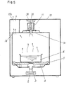
- a heat conductive plate 38 is disposed above the vapor hole 36 in the body cap 27 of the jack body 26.
- the probe rotating and supporting device 11 When the high-frequency heating apparatus is used with the temperature probe being not used, the probe rotating and supporting device 11 is exposed directlyto vapor, oil orfood stock generated from a heated food in the heating chamber. However, vapor entering into the device 11 through the sleeve 30 is discharged to the outside after having passed through the vapor hole 36 in the body cap 27 at its center portion, thereby to restrain dew condensation of such vapor.
- the insulation walls 34 and 35 separate such condensed waterdrops from the contact pieces, thereby to prevent the contact pieces having different polarities from being short-circuited.
- a vapor absorbing material such as cushion rubber may be used. With the use of such vapor absorbing material, stable electric output may be taken out at all times.
- Fig. 6 is another example of a dew condensation preventive arrangement in which a dew condensation member 39 of the cone shape is disposed on the probe rotating and supporting device 11.
- a dew condensation member 39 of the cone shape is disposed on the probe rotating and supporting device 11.
- vapor discharged through the vapor hole 36 is condensed at the cone-shape dew condensation member 39 disposed above the probe rotating and supporting device 11, the size of the member 39 being larger than that of the probe rotating and supporting device 11.
- Waterdrops thus converted from the vapor flow along the peripheral edge of the cone-shape member 39 and then fall on the oven top plate 1A.
- the output portions 28 are not electrically conducted by waterdrops, thus eliminating the risk of malfunction.
- the mounting metal 20 and the oven top plate 1A form a choke circuit, and connection between the temperature probe 7 and the sleeve 30 of the jack 11 is made in metal.
- the high-frequency heating apparatus in accordance with the present invention may be safely used without any leakage of electric waves in the oven chamber 1.
- the plug 10 of the temperature probe 7 may be attached to or removed from the oven chamber 1.
- the plug 10 itself may be rotated together with the food 6.
- the present invention provides a highly reliable device for rotating and supporting a temperature probe to be used in a high-frequency heating apparatus, which assures rotation of the probe plug with a simple construction and eliminates malfunction resulted from dirt such as vapor, oil or food stock generated from a heated food.
Landscapes
- Physics & Mathematics (AREA)
- General Physics & Mathematics (AREA)
- Electromagnetism (AREA)
- Electric Ovens (AREA)
- Measuring Temperature Or Quantity Of Heat (AREA)
Claims (3)
Applications Claiming Priority (6)
| Application Number | Priority Date | Filing Date | Title |
|---|---|---|---|
| JP219816/83 | 1983-11-22 | ||
| JP58219816A JPS60111822A (ja) | 1983-11-22 | 1983-11-22 | 高周波加熱装置 |
| JP59114971A JPS60259835A (ja) | 1984-06-04 | 1984-06-04 | 調理器 |
| JP114971/84 | 1984-06-04 | ||
| JP116964/84 | 1984-06-07 | ||
| JP59116964A JPS60263033A (ja) | 1984-06-07 | 1984-06-07 | 高周波加熱装置 |
Publications (3)
| Publication Number | Publication Date |
|---|---|
| EP0163744A1 EP0163744A1 (de) | 1985-12-11 |
| EP0163744A4 EP0163744A4 (de) | 1986-06-05 |
| EP0163744B1 true EP0163744B1 (de) | 1989-02-01 |
Family
ID=27312867
Family Applications (1)
| Application Number | Title | Priority Date | Filing Date |
|---|---|---|---|
| EP84904172A Expired EP0163744B1 (de) | 1983-11-22 | 1984-11-16 | Vorrichtung zum rotierenden halten einer temperatursonde |
Country Status (5)
| Country | Link |
|---|---|
| EP (1) | EP0163744B1 (de) |
| AU (1) | AU561766B2 (de) |
| CA (1) | CA1228648A (de) |
| DE (1) | DE3476575D1 (de) |
| WO (1) | WO1985002456A1 (de) |
Families Citing this family (4)
| Publication number | Priority date | Publication date | Assignee | Title |
|---|---|---|---|---|
| DE10051511A1 (de) * | 2000-10-17 | 2002-04-25 | Bsh Bosch Siemens Hausgeraete | Steckdose für ein Bratenthermometer |
| US20090038928A1 (en) * | 2007-08-08 | 2009-02-12 | Tyco Electronics Corporation | Spring loaded contact for rotary interface |
| DE102009002216A1 (de) * | 2009-04-06 | 2010-10-07 | BSH Bosch und Siemens Hausgeräte GmbH | Hausgerätevorrichtung |
| CN113805024B (zh) * | 2020-05-27 | 2024-08-13 | 山东华光光电子股份有限公司 | 一种可实现不同极性半导体激光器测试的装置与测试方法 |
Citations (3)
| Publication number | Priority date | Publication date | Assignee | Title |
|---|---|---|---|---|
| JPS4326846Y1 (de) * | 1966-05-14 | 1968-11-07 | ||
| JPS5553643A (en) * | 1978-10-12 | 1980-04-19 | Sharp Corp | Electronic oven |
| JPS5635784U (de) * | 1979-08-27 | 1981-04-07 |
Family Cites Families (7)
| Publication number | Priority date | Publication date | Assignee | Title |
|---|---|---|---|---|
| US3408610A (en) * | 1967-04-10 | 1968-10-29 | Anthony T. Clarkson | Rotatable coaxial coupling |
| US3957331A (en) * | 1974-06-03 | 1976-05-18 | Component Manufacturing Service, Inc. | Swivel connector for electrical appliances |
| US4149056A (en) * | 1976-05-13 | 1979-04-10 | Sharp Kabushiki Kaisha | Microwave oven with food temperature-sensing means |
| JPS54155759U (de) * | 1978-04-20 | 1979-10-30 | ||
| JPS6119371Y2 (de) * | 1980-03-17 | 1986-06-11 | ||
| US4547643A (en) * | 1982-10-06 | 1985-10-15 | Sharp Kabushiki Kaisha | Temperature sensing probe for microwave oven application |
| DE3427261C2 (de) * | 1983-08-31 | 1986-05-22 | Hosiden Electronics Co., Ltd., Osaka | Elektrische Anschlußbuchse |
-
1984
- 1984-11-16 WO PCT/JP1984/000551 patent/WO1985002456A1/ja not_active Ceased
- 1984-11-16 EP EP84904172A patent/EP0163744B1/de not_active Expired
- 1984-11-16 DE DE8484904172T patent/DE3476575D1/de not_active Expired
- 1984-11-16 AU AU36711/84A patent/AU561766B2/en not_active Ceased
- 1984-11-21 CA CA000468297A patent/CA1228648A/en not_active Expired
Patent Citations (3)
| Publication number | Priority date | Publication date | Assignee | Title |
|---|---|---|---|---|
| JPS4326846Y1 (de) * | 1966-05-14 | 1968-11-07 | ||
| JPS5553643A (en) * | 1978-10-12 | 1980-04-19 | Sharp Corp | Electronic oven |
| JPS5635784U (de) * | 1979-08-27 | 1981-04-07 |
Also Published As
| Publication number | Publication date |
|---|---|
| WO1985002456A1 (en) | 1985-06-06 |
| EP0163744A4 (de) | 1986-06-05 |
| DE3476575D1 (en) | 1989-03-09 |
| AU3671184A (en) | 1985-06-13 |
| CA1228648A (en) | 1987-10-27 |
| EP0163744A1 (de) | 1985-12-11 |
| AU561766B2 (en) | 1987-05-14 |
Similar Documents
| Publication | Publication Date | Title |
|---|---|---|
| US4747712A (en) | Device for rotating and supporting a temperature probe | |
| US4967049A (en) | Adjusting member for a temperature sensing probe | |
| US3899655A (en) | Oven, heating element and socket assembly | |
| EP0163744B1 (de) | Vorrichtung zum rotierenden halten einer temperatursonde | |
| US4547643A (en) | Temperature sensing probe for microwave oven application | |
| EP0224074A3 (de) | Verteilungsgerät mit herausziehbarem Überspannungsableiter | |
| US4752664A (en) | Microwave oven with a removably attached heater | |
| SE469153B (sv) | Koaxialkabelgenomfoering | |
| US1828276A (en) | Connecting device | |
| GB1580411A (en) | Microwave oven with food temperature sensing means | |
| JPS60259835A (ja) | 調理器 | |
| CA1216037A (en) | Slipping connector assembly for microwave oven application | |
| JPH0319448B2 (de) | ||
| KR840001720Y1 (ko) | 전자레인지의 온도 프로브 취부 회전장치 | |
| EP0986292A3 (de) | Wärmeleitende Einlegematte für elektrische und elektronische Geräte | |
| CN223025879U (zh) | 加热结构和烹饪器具 | |
| KR100299825B1 (ko) | 전자렌지의 무게센서 조립체 | |
| KR100277963B1 (ko) | 전자렌지의 무게센서 조립체 | |
| JPS60263032A (ja) | 高周波加熱装置 | |
| KR950004061Y1 (ko) | 전자조리기의 중량 전달장치 | |
| KR200147227Y1 (ko) | 전자렌지용 온도감지기의 결합구조 | |
| KR800000422Y1 (ko) | 로타리 스위치 | |
| KR800001367Y1 (ko) | 콘세트의 안전 카바장치 | |
| JPH0126337Y2 (de) | ||
| KR930002060Y1 (ko) | 리드선의 심선꼬임장치 |
Legal Events
| Date | Code | Title | Description |
|---|---|---|---|
| PUAI | Public reference made under article 153(3) epc to a published international application that has entered the european phase |
Free format text: ORIGINAL CODE: 0009012 |
|
| 17P | Request for examination filed |
Effective date: 19850719 |
|
| AK | Designated contracting states |
Designated state(s): DE FR GB SE |
|
| RIN1 | Information on inventor provided before grant (corrected) |
Inventor name: MASUBUCHI, TOSHIO Inventor name: GONOH, AKIRA |
|
| A4 | Supplementary search report drawn up and despatched |
Effective date: 19860605 |
|
| 17Q | First examination report despatched |
Effective date: 19861218 |
|
| GRAA | (expected) grant |
Free format text: ORIGINAL CODE: 0009210 |
|
| AK | Designated contracting states |
Kind code of ref document: B1 Designated state(s): DE FR GB SE |
|
| REF | Corresponds to: |
Ref document number: 3476575 Country of ref document: DE Date of ref document: 19890309 |
|
| ET | Fr: translation filed | ||
| PLBE | No opposition filed within time limit |
Free format text: ORIGINAL CODE: 0009261 |
|
| STAA | Information on the status of an ep patent application or granted ep patent |
Free format text: STATUS: NO OPPOSITION FILED WITHIN TIME LIMIT |
|
| 26N | No opposition filed | ||
| PGFP | Annual fee paid to national office [announced via postgrant information from national office to epo] |
Ref country code: GB Payment date: 19941108 Year of fee payment: 11 |
|
| PGFP | Annual fee paid to national office [announced via postgrant information from national office to epo] |
Ref country code: FR Payment date: 19941109 Year of fee payment: 11 |
|
| PGFP | Annual fee paid to national office [announced via postgrant information from national office to epo] |
Ref country code: DE Payment date: 19941110 Year of fee payment: 11 |
|
| PGFP | Annual fee paid to national office [announced via postgrant information from national office to epo] |
Ref country code: SE Payment date: 19941116 Year of fee payment: 11 |
|
| EAL | Se: european patent in force in sweden |
Ref document number: 84904172.8 |
|
| PG25 | Lapsed in a contracting state [announced via postgrant information from national office to epo] |
Ref country code: GB Effective date: 19951116 |
|
| PG25 | Lapsed in a contracting state [announced via postgrant information from national office to epo] |
Ref country code: SE Effective date: 19951117 |
|
| GBPC | Gb: european patent ceased through non-payment of renewal fee |
Effective date: 19951116 |
|
| PG25 | Lapsed in a contracting state [announced via postgrant information from national office to epo] |
Ref country code: FR Effective date: 19960731 |
|
| PG25 | Lapsed in a contracting state [announced via postgrant information from national office to epo] |
Ref country code: DE Effective date: 19960801 |
|
| EUG | Se: european patent has lapsed |
Ref document number: 84904172.8 |
|
| REG | Reference to a national code |
Ref country code: FR Ref legal event code: ST |