EP0163788A1 - Support ajustable pour écran de visualisation - Google Patents
Support ajustable pour écran de visualisation Download PDFInfo
- Publication number
- EP0163788A1 EP0163788A1 EP84303888A EP84303888A EP0163788A1 EP 0163788 A1 EP0163788 A1 EP 0163788A1 EP 84303888 A EP84303888 A EP 84303888A EP 84303888 A EP84303888 A EP 84303888A EP 0163788 A1 EP0163788 A1 EP 0163788A1
- Authority
- EP
- European Patent Office
- Prior art keywords
- support
- carrier
- display monitor
- turntable
- support beam
- Prior art date
- Legal status (The legal status is an assumption and is not a legal conclusion. Google has not performed a legal analysis and makes no representation as to the accuracy of the status listed.)
- Granted
Links
Images


Classifications
-
- F—MECHANICAL ENGINEERING; LIGHTING; HEATING; WEAPONS; BLASTING
- F16—ENGINEERING ELEMENTS AND UNITS; GENERAL MEASURES FOR PRODUCING AND MAINTAINING EFFECTIVE FUNCTIONING OF MACHINES OR INSTALLATIONS; THERMAL INSULATION IN GENERAL
- F16M—FRAMES, CASINGS OR BEDS OF ENGINES, MACHINES OR APPARATUS, NOT SPECIFIC TO ENGINES, MACHINES OR APPARATUS PROVIDED FOR ELSEWHERE; STANDS; SUPPORTS
- F16M11/00—Stands or trestles as supports for apparatus or articles placed thereon ; Stands for scientific apparatus such as gravitational force meters
- F16M11/20—Undercarriages with or without wheels
- F16M11/24—Undercarriages with or without wheels changeable in height or length of legs, also for transport only, e.g. by means of tubes screwed into each other
-
- F—MECHANICAL ENGINEERING; LIGHTING; HEATING; WEAPONS; BLASTING
- F16—ENGINEERING ELEMENTS AND UNITS; GENERAL MEASURES FOR PRODUCING AND MAINTAINING EFFECTIVE FUNCTIONING OF MACHINES OR INSTALLATIONS; THERMAL INSULATION IN GENERAL
- F16M—FRAMES, CASINGS OR BEDS OF ENGINES, MACHINES OR APPARATUS, NOT SPECIFIC TO ENGINES, MACHINES OR APPARATUS PROVIDED FOR ELSEWHERE; STANDS; SUPPORTS
- F16M11/00—Stands or trestles as supports for apparatus or articles placed thereon ; Stands for scientific apparatus such as gravitational force meters
- F16M11/02—Heads
- F16M11/18—Heads with mechanism for moving the apparatus relatively to the stand
-
- F—MECHANICAL ENGINEERING; LIGHTING; HEATING; WEAPONS; BLASTING
- F16—ENGINEERING ELEMENTS AND UNITS; GENERAL MEASURES FOR PRODUCING AND MAINTAINING EFFECTIVE FUNCTIONING OF MACHINES OR INSTALLATIONS; THERMAL INSULATION IN GENERAL
- F16M—FRAMES, CASINGS OR BEDS OF ENGINES, MACHINES OR APPARATUS, NOT SPECIFIC TO ENGINES, MACHINES OR APPARATUS PROVIDED FOR ELSEWHERE; STANDS; SUPPORTS
- F16M11/00—Stands or trestles as supports for apparatus or articles placed thereon ; Stands for scientific apparatus such as gravitational force meters
- F16M11/20—Undercarriages with or without wheels
- F16M11/2007—Undercarriages with or without wheels comprising means allowing pivoting adjustment
- F16M11/2014—Undercarriages with or without wheels comprising means allowing pivoting adjustment around a vertical axis
-
- F—MECHANICAL ENGINEERING; LIGHTING; HEATING; WEAPONS; BLASTING
- F16—ENGINEERING ELEMENTS AND UNITS; GENERAL MEASURES FOR PRODUCING AND MAINTAINING EFFECTIVE FUNCTIONING OF MACHINES OR INSTALLATIONS; THERMAL INSULATION IN GENERAL
- F16M—FRAMES, CASINGS OR BEDS OF ENGINES, MACHINES OR APPARATUS, NOT SPECIFIC TO ENGINES, MACHINES OR APPARATUS PROVIDED FOR ELSEWHERE; STANDS; SUPPORTS
- F16M2200/00—Details of stands or supports
- F16M2200/02—Locking means
- F16M2200/025—Locking means for translational movement
- F16M2200/027—Locking means for translational movement by friction
-
- F—MECHANICAL ENGINEERING; LIGHTING; HEATING; WEAPONS; BLASTING
- F16—ENGINEERING ELEMENTS AND UNITS; GENERAL MEASURES FOR PRODUCING AND MAINTAINING EFFECTIVE FUNCTIONING OF MACHINES OR INSTALLATIONS; THERMAL INSULATION IN GENERAL
- F16M—FRAMES, CASINGS OR BEDS OF ENGINES, MACHINES OR APPARATUS, NOT SPECIFIC TO ENGINES, MACHINES OR APPARATUS PROVIDED FOR ELSEWHERE; STANDS; SUPPORTS
- F16M2200/00—Details of stands or supports
- F16M2200/08—Foot or support base
-
- Y—GENERAL TAGGING OF NEW TECHNOLOGICAL DEVELOPMENTS; GENERAL TAGGING OF CROSS-SECTIONAL TECHNOLOGIES SPANNING OVER SEVERAL SECTIONS OF THE IPC; TECHNICAL SUBJECTS COVERED BY FORMER USPC CROSS-REFERENCE ART COLLECTIONS [XRACs] AND DIGESTS
- Y10—TECHNICAL SUBJECTS COVERED BY FORMER USPC
- Y10S—TECHNICAL SUBJECTS COVERED BY FORMER USPC CROSS-REFERENCE ART COLLECTIONS [XRACs] AND DIGESTS
- Y10S248/00—Supports
- Y10S248/917—Video display screen support
- Y10S248/919—Adjustably orientable video screen support
- Y10S248/92—Angular and linear video display screen support adjustment
-
- Y—GENERAL TAGGING OF NEW TECHNOLOGICAL DEVELOPMENTS; GENERAL TAGGING OF CROSS-SECTIONAL TECHNOLOGIES SPANNING OVER SEVERAL SECTIONS OF THE IPC; TECHNICAL SUBJECTS COVERED BY FORMER USPC CROSS-REFERENCE ART COLLECTIONS [XRACs] AND DIGESTS
- Y10—TECHNICAL SUBJECTS COVERED BY FORMER USPC
- Y10S—TECHNICAL SUBJECTS COVERED BY FORMER USPC CROSS-REFERENCE ART COLLECTIONS [XRACs] AND DIGESTS
- Y10S248/00—Supports
- Y10S248/917—Video display screen support
- Y10S248/919—Adjustably orientable video screen support
- Y10S248/921—Plural angular
Definitions
- This invention relates to an adjustable support for a display monitor, and more particular a support which allows the display monitor to be tilted, swivelled and adjusted for height.
- adjustable supports In recent years, in an effort to improve their ergonomics, display monitors in display terminals for data entry, data processing or word processing have been mounted on adjustable supports. Most of these adjustable supports, exemplified by the mechanisms described in European Patent Specifications 16,913A, 41,804A, 70,336A and 70,337A, and US Patent Specifications 3,970,792, 4,365,779, 4,395,010, 4,410,159 and 4,415,136 allow swivelling and tilting only, normally by using two matching spherical surfaces.
- Some supports also allow height adjustment, as exemplified by US Patent Specification 4,304,385 and European Patent Specifications 46,225A and German Patent Specification 3036852A.
- the latter uses a gas strut (or gas spring) to counter-balance the weight of the display monitor: other mechanisms employ counter-balancing springs.
- a typical monitor can weigh 15 to 20 Kg.
- the Tektronix ADS 01 adjustable display support for the Tektronix 4105 display uses a gas strut to compensate for the weight of the display which is carried on a swinging cradle supported by a pair of telescopic columns.
- the gas strut is located horizontally in the base of the assembly and is linked to the cradle supports by a system of cables, pulleys and levers.
- an adjustable support for a display monitor comprises an adjustable support for a display monitor comprising a turntable, a pair of vertically-extending support columns at least one of which is hollow to contain a gas strut of non-magnetic material, a slidable support beam supported on and slidable alongside support columns thereby to vary the height of the support beam relative to the turntable, a support carrier mounted on said support beam in such a manner that the angle between the carrier and the beam can be varied, and means for securing a display monitor to the support carrier, the gas strut being secured by one end to the turntable and its other end to the support beam to counterbalance the weight of a display monitor secured on the carrier thereby to assist in the raising and lowering of the support beam along the support columns.
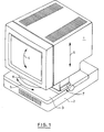
- a display terminal includes a display monitor (1) mounted on a logic unit (2) by means of an adjustable support (3).
- the support allows the display monitor to be tilted as represented by arrow (4) to allow the vertical angle of the screen of the display to be adjusted to the optimum viewing angle and swivelled as represented by arrows (5) to allow selection of the azimuth.
- the monitor (1) can also be adjusted for height, as represented by arrows (6), by means of a height control (7).
- a turntable (8) which allows swivelling of the monitor with respect to the logic unit (2).
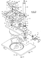
- FIG. 2 is an exploded view of the support (3) which includes a plinth (9), preferably of die cast aluminium although plastics material could also be used, carrying feet (10) of cork, rubber or soft plastics material.
- a recess (11) containing a central boss (12) receives a friction ring (13) of nylon, acetal, PTFE or other low friction material.
- An integral peg (14) located within a slot (15) in the friction ring (13) prevents rotation of the latter.
- the peg (14) is also located in an arcuate groove (not shown) in the bottom surface of turntable (8) to limit the rotation of the latter.
- the turntable (8) is secured within the recess (11) by means of a spindle, not shown, passing through the central boss (12), and a nut (16), the tightness of which controls the force required to rotate the turntable (8).
- the turntable (8) preferably of die-cast aluminium but alternatively of suitable plastics material has an integrally formed arm (17) which carries support tubes (18) and (19) secured by plates (20), welded to the support tubes and only one of which is shown.
- the support tubes (18) and (19) are made from non-magnetic stainless steel such as type 304.
- Located within the support tube (18) is a gas strut (21) having a non-magnetic brass cylinder (24) and a non-magnetic stainless steel piston rod (22) secured to the plate (20) by means of a circlip (23).
- a beam (25), preferably of die-cast aluminium is slidably mounted on the support tubes (18) and (19) by means of integral collars (26) and (27) respectively each of which contains a pair of bearings, not shown.
- the upper part of at least the collar (26) is threaded to receive a threaded retainer (28), preferably an impact extrusion of aluminium to which the gas strut (21) is secured by means of nut (29).
- Recesses (30) in the beam (25) locate a pair of plastic skid pads (31), parts (32) of which protrude through slots (33) in a platform or carrier (34) preferably made from die-cast aluminium.
- the carrier (34) which has a cylindrical lower surface, is urged against the upper surfaces of the skid pads (31) by means of spring loaded rollers (35) secured to the beam (25) by bolts or screws (36).
- Holes (37) in the carrier (34) and recesses (38) receive the feet (not shown) of the display monitor (1) ( Figure 1) when it is placed on the carrier (34).
- the monitor is latched onto the carrier (34) by means of a slidable latch (39), preferably of plastics material, slidable in direction (40) against the action of integral spring fingers (41).
- the latch (39) is retained in the carrier (34) by means of integrally formed retainers (42). Camming surfaces (43) on the latch (39) operate the latch (39) as the display monitor is lowered onto the carrier (34), guide plate (44) serving to guide the monitor in association with a corresponding slot in the underside of the monitor.
- the latch (39) can be released against the spring pressure of fingers (41) acting on walls (45) by inserting a finger upwardly through aperture (46) to locate the release tab (47).
- the support beam (25) also carries a pair of bearing blocks (48) carrying pinions (49) on a shaft (50), the end (51) of which is of a non-circular cross section to allow the shaft (50) to be locked against rotation by means of a slidable latch plate (52) having a latch cover (53).
- a guide block or post (54) serves to guide and retain the slotted locking plate (52).
- a control knob (55) is provided to assist rotation of the shaft (50) and pinions (49) which co-operate with racks on the rear of the support tubes (18) and (19).
- the recess (56) in the plinth (9) is provided to allow for a cooling fan, not shown, provided at the rear of the logic unit (2).
- Figure 3 is a part sectional view from the rear of the support assembly showing how racks (57) are provided on the support tubes or columns (18) and (19).
- the gas strut cylinder (24) is secured to collar (26) by means of the retainer (28), which as stated above is preferably joined to the collar (26) by means of a screw threaded portion (58).
- An important function served by the pinions (49), shaft (50) and racks (57) is to equalize the load on the two support columns (18) and (19). This ensures smooth movement of the display monitor (1), carried on beam (25) and carrier (34) (not shown in Figure 3) up and down the columns.
- a secondary but important role of the rack and pinions is to allow adjustment of the height by means of control knob or wheel (55).
- FIG 4 is a part sectional view showing the relationship between the carrier (34) and support beam (25).
- Skid pads (31) are secured within recesses (30) in the surface of beam (25). Integral parts (32) of the skid pads (31) protrude through slots (33) in the carrier (34) and carry blocks (59) carrying rollers (35).
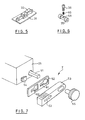
- the skid pad is shown in more detail in Figure 5.
- the blocks (59) are secured to the beam (25) by means of screws (36) which pass through apertures in blocks (59) and skid pads (31).
- a spring (60) urges the rollers (35)/block (59) against the upper surface of carrier (34), urging the lower surface of the latter against the upper surface of the skid pads (31).
- the friction between the skid pads (31) and the cylindrical carrier surface is adjusted by means of the screws (36).
- the spring (60) is contained within a counter bore in the block (59) leaving a small gap between the screwhead and the block to limit rocking of the carrier (34) with respect to the beam (25).
- FIG. 7 shows the height adjustment lock or latch in more detail.
- the slidable latch plate (52) is provided with a keyhole-shaped slot (61) and a slot (62) which co-operates with guide block (54).
- the shaft end (51) will be locked or free to rotate depending upon the position ot the key plate (52).
- the plate (52) and cover (53) are moved in the opposite direction.
- Figure 8 is a plan view of the carrier (34) showing its relationship with the latch mechanism (39).
- Spring fingers (41) acting against walls (45) urge the latch (39) downwardly as viewed in Figure 8 within the retainers (42).
- a monitor When a monitor is lowered onto the carrier (34) it is guided into position by the guide plate (44), apertures (37) and recesses (38) accommodating the teet of the monitor. Parts in the monitor co-operate with the camming surfaces (43) to urge the latch (39) towards the walls (45) against the spring pressure exerted by the spring fingers (41).
- the latch (39) will spring forward to secure the monitor to the carrier (34).
- release tab (47) which can be operated by a finger inserted through the aperture (46).
- Figure 9 is an isometric view corresponding to Figure 1 showing the carrier (34) m its lowermost position with the monitor removed. This is the preferred position for the monitor to be latched to the support. The main parts of the support are clearly visible.
- an adjustable support for a display monitor which allows the height and viewing angle of the display screen to be adjusted to an optimum position.
- the assembly can be modified for monitors of varying weights by careful choice of the gas strut and adjustment of the friction between the carrier and the skid pads.
- the structure is relatively simple and inexpensive: in fact if it is desired to provide only a tilt and swivel mechanism and not to provide height adjustments, the turntable (8), support beam (25), support tubes (18) and (19), and the gas strut can be replaced by a simple turntable whose upper surface is adapted to receive the skid pads (31).
- the carrier (34) and latch (39) can remain the same.
- Such a flexible construction leads to economy of manufacture.
Landscapes
- Engineering & Computer Science (AREA)
- General Engineering & Computer Science (AREA)
- Mechanical Engineering (AREA)
- Devices For Indicating Variable Information By Combining Individual Elements (AREA)
Priority Applications (4)
| Application Number | Priority Date | Filing Date | Title |
|---|---|---|---|
| EP84303888A EP0163788B1 (fr) | 1984-06-08 | 1984-06-08 | Support ajustable pour écran de visualisation |
| DE8484303888T DE3480959D1 (de) | 1984-06-08 | 1984-06-08 | Verstellbares untengestell fuer datensichtgeraet. |
| JP60037729A JPS60263985A (ja) | 1984-06-08 | 1985-02-28 | 表示モニタ支持装置 |
| US06/742,260 US4640485A (en) | 1984-06-08 | 1985-06-07 | Adjustable support for display monitor |
Applications Claiming Priority (1)
| Application Number | Priority Date | Filing Date | Title |
|---|---|---|---|
| EP84303888A EP0163788B1 (fr) | 1984-06-08 | 1984-06-08 | Support ajustable pour écran de visualisation |
Publications (2)
| Publication Number | Publication Date |
|---|---|
| EP0163788A1 true EP0163788A1 (fr) | 1985-12-11 |
| EP0163788B1 EP0163788B1 (fr) | 1990-01-03 |
Family
ID=8192656
Family Applications (1)
| Application Number | Title | Priority Date | Filing Date |
|---|---|---|---|
| EP84303888A Expired - Lifetime EP0163788B1 (fr) | 1984-06-08 | 1984-06-08 | Support ajustable pour écran de visualisation |
Country Status (4)
| Country | Link |
|---|---|
| US (1) | US4640485A (fr) |
| EP (1) | EP0163788B1 (fr) |
| JP (1) | JPS60263985A (fr) |
| DE (1) | DE3480959D1 (fr) |
Cited By (3)
| Publication number | Priority date | Publication date | Assignee | Title |
|---|---|---|---|---|
| EP0738853A3 (fr) * | 1995-03-22 | 1996-11-27 | Canon Kk | |
| GB2338894A (en) * | 1998-06-18 | 2000-01-12 | Grorud Eng Ltd | Support, particularly for flat-panel monitors |
| EP2112419A3 (fr) * | 2008-04-23 | 2010-01-13 | Funai Electric Co., Ltd. | Appareil de rotation d'écran d'affichage |
Families Citing this family (40)
| Publication number | Priority date | Publication date | Assignee | Title |
|---|---|---|---|---|
| US4884420A (en) * | 1986-02-24 | 1989-12-05 | Dennis E. McGoldrick, Trustee | Cage with floating nut assembly |
| JPS62243016A (ja) * | 1986-04-16 | 1987-10-23 | Mitsubishi Electric Corp | グラフイツクスデイスプレイ装置 |
| USD309896S (en) | 1986-10-21 | 1990-08-14 | International Business Machines Corporation | Display monitor |
| USD311180S (en) | 1986-10-21 | 1990-10-09 | International Business Machines Corporation | Display monitor |
| USD306580S (en) | 1987-10-12 | 1990-03-13 | IDEA Courier Incorporated | Computer terminal |
| US5299338A (en) * | 1988-01-15 | 1994-04-05 | Hill-Rom Company, Inc. | Hospital bed with pivoting headboard |
| USD312630S (en) | 1988-06-30 | 1990-12-04 | Next, Inc. | Computer monitor and stand |
| US4919387A (en) * | 1989-03-06 | 1990-04-24 | Bell & Howell Publication Systems Company | Tilt and swivel support apparatus |
| US5466078A (en) * | 1989-07-07 | 1995-11-14 | Health Care Keyboard Company | Input keyboard apparatus for information processing and other keyboard devices |
| US5101736A (en) * | 1990-05-17 | 1992-04-07 | Bommarito Paul F | Adjustable surface desk for computers |
| DE4214341A1 (de) * | 1992-05-09 | 1993-11-11 | Ivan Mallinowski | Computergehäuse mit Monitorstandfläche, welche arbeitsspezifisch verstellt werden kann |
| US5330147A (en) * | 1993-01-22 | 1994-07-19 | Mayline Company, Inc. | Video monitor clamp |
| US5668570A (en) * | 1993-06-29 | 1997-09-16 | Ditzik; Richard J. | Desktop computer with adjustable flat panel screen |
| US5488453A (en) * | 1994-07-29 | 1996-01-30 | Eastman Kodak Company | Operator control interface mounting mechanism |
| USD376787S (en) | 1994-12-14 | 1996-12-24 | Vu Ryte, Inc. | Video display pedestal |
| US5713549A (en) * | 1995-05-22 | 1998-02-03 | Shieh; En-Ru | Monitor support device |
| USD390546S (en) | 1996-04-12 | 1998-02-10 | Vu Ryte, Inc. | Video display pedestal |
| USD393633S (en) | 1996-10-21 | 1998-04-21 | Minnesota Mining And Manufacturing Company | Monitor support stand |
| USD399834S (en) | 1997-03-31 | 1998-10-20 | Vu Ryte, Inc. | Video display pedestal |
| JP3537319B2 (ja) * | 1998-08-06 | 2004-06-14 | 富士通株式会社 | 電子装置を傾斜及び回転自在に支持するための支持装置及び表示装置 |
| KR100279633B1 (ko) * | 1998-12-08 | 2001-02-01 | 구자홍 | 2축 동력회전장치와 그 제어방법 |
| US6510049B2 (en) * | 2000-01-06 | 2003-01-21 | Rosen Products Llc | Adjustable display monitor unit |
| TW495130U (en) * | 2001-02-09 | 2002-07-11 | Acer Inc | Flat display device and the rotatory structure thereof |
| WO2003014871A2 (fr) | 2001-08-03 | 2003-02-20 | Hill-Rom Services, Inc. | Systeme informatique sur lieu de traitement d'un patient |
| KR100461178B1 (ko) * | 2002-03-26 | 2004-12-13 | 삼성전자주식회사 | 모니터장치 |
| AU2003261591B2 (en) * | 2002-09-17 | 2009-01-08 | Sharp Kabushiki Kaisha | Thin display device |
| JP4965186B2 (ja) * | 2006-03-30 | 2012-07-04 | 下西技研工業株式会社 | 平面ディスプレイの駆動装置 |
| CN101555977B (zh) * | 2008-04-11 | 2011-06-22 | 鸿富锦精密工业(深圳)有限公司 | 支撑装置 |
| US8650682B2 (en) * | 2010-03-02 | 2014-02-18 | Hill-Rom Services, Inc. | Multifunctional display for hospital bed |
| EP2374439A3 (fr) | 2010-04-09 | 2015-11-25 | Hill-Rom Services, Inc. | Support de patient, communication et appareil de calcul |
| US20120205325A1 (en) * | 2011-02-08 | 2012-08-16 | DCI Marketing, Inc. (a Wisconsin corporation) | Product display system |
| US9228885B2 (en) | 2012-06-21 | 2016-01-05 | Hill-Rom Services, Inc. | Patient support systems and methods of use |
| US9539155B2 (en) | 2012-10-26 | 2017-01-10 | Hill-Rom Services, Inc. | Control system for patient support apparatus |
| US10474808B2 (en) | 2013-03-29 | 2019-11-12 | Hill-Rom Services, Inc. | Hospital bed compatibility with third party application software |
| GB201517487D0 (en) * | 2015-10-03 | 2015-11-18 | Choquette Samuel | Rotatable platter for visual display having a passage for wiring and a stopper |
| US10829009B2 (en) * | 2018-06-27 | 2020-11-10 | Faurecia Automotive Seating, Llc | Vehicle seat height adjustment mechanism |
| US11371644B2 (en) | 2019-05-31 | 2022-06-28 | Apple Inc. | Dual display stand |
| WO2021091547A1 (fr) * | 2019-11-06 | 2021-05-14 | Hewlett-Packard Development Company, L.P. | Supports de dispositif informatique et espaceurs d'interface de support d'affichage |
| WO2024010106A1 (fr) * | 2022-07-05 | 2024-01-11 | 엘지전자 주식회사 | Appareil de support et dispositif d'affichage le comprenant |
| US20250369562A1 (en) * | 2024-05-31 | 2025-12-04 | Lockheed Martin Corporation | Adjustment assembly for display unit |
Citations (2)
| Publication number | Priority date | Publication date | Assignee | Title |
|---|---|---|---|---|
| EP0070336A1 (fr) * | 1981-07-20 | 1983-01-26 | International Business Machines Corporation | Support inclinable et/ou pivotant pour un dispositif de visualisation |
| DE3036852C2 (de) * | 1980-09-30 | 1984-02-23 | Tandberg Data A/S, Oslo | Vorrichtung zum Aufstellen eines Datensichtgerätes auf einer Arbeitsfläche |
Family Cites Families (8)
| Publication number | Priority date | Publication date | Assignee | Title |
|---|---|---|---|---|
| US1196084A (en) * | 1916-08-29 | William b | ||
| US1065280A (en) * | 1912-03-08 | 1913-06-17 | Ira L Stanger | Adjustable seat. |
| US3970792A (en) * | 1975-02-18 | 1976-07-20 | International Telephone And Telegraph Corporation | Adjustable mounting structure for video telephone unit |
| US3993278A (en) * | 1975-03-12 | 1976-11-23 | Motorola, Inc. | Latch mechanism for mounting bracket assembly |
| GB2096234B (en) * | 1981-04-03 | 1985-02-20 | Mouldmaking Design Centre Ltd | Swivel mounting |
| US4410159A (en) * | 1981-07-14 | 1983-10-18 | Sperry Corporation | Adjustable support for a video display terminal |
| JPS61500135A (ja) * | 1983-10-11 | 1986-01-23 | テクトロニツクス インコ−ポレイテツド | コンピュ−タ・タ−ミナル・スタンド |
| US4533105A (en) * | 1984-04-27 | 1985-08-06 | Zenith Electronics Corporation | Tiltable display monitor assembly |
-
1984
- 1984-06-08 DE DE8484303888T patent/DE3480959D1/de not_active Expired - Lifetime
- 1984-06-08 EP EP84303888A patent/EP0163788B1/fr not_active Expired - Lifetime
-
1985
- 1985-02-28 JP JP60037729A patent/JPS60263985A/ja active Granted
- 1985-06-07 US US06/742,260 patent/US4640485A/en not_active Expired - Fee Related
Patent Citations (2)
| Publication number | Priority date | Publication date | Assignee | Title |
|---|---|---|---|---|
| DE3036852C2 (de) * | 1980-09-30 | 1984-02-23 | Tandberg Data A/S, Oslo | Vorrichtung zum Aufstellen eines Datensichtgerätes auf einer Arbeitsfläche |
| EP0070336A1 (fr) * | 1981-07-20 | 1983-01-26 | International Business Machines Corporation | Support inclinable et/ou pivotant pour un dispositif de visualisation |
Cited By (5)
| Publication number | Priority date | Publication date | Assignee | Title |
|---|---|---|---|---|
| EP0738853A3 (fr) * | 1995-03-22 | 1996-11-27 | Canon Kk | |
| US6216989B1 (en) | 1995-03-22 | 2001-04-17 | Canon Kabushiki Kaisha | Support structure and display apparatus equipped with the support structure |
| GB2338894A (en) * | 1998-06-18 | 2000-01-12 | Grorud Eng Ltd | Support, particularly for flat-panel monitors |
| EP2112419A3 (fr) * | 2008-04-23 | 2010-01-13 | Funai Electric Co., Ltd. | Appareil de rotation d'écran d'affichage |
| US8205849B2 (en) | 2008-04-23 | 2012-06-26 | Funai Electric Co., Ltd. | Display screen turning apparatus and television set |
Also Published As
| Publication number | Publication date |
|---|---|
| US4640485A (en) | 1987-02-03 |
| DE3480959D1 (de) | 1990-02-08 |
| JPH0336435B2 (fr) | 1991-05-31 |
| EP0163788B1 (fr) | 1990-01-03 |
| JPS60263985A (ja) | 1985-12-27 |
Similar Documents
| Publication | Publication Date | Title |
|---|---|---|
| EP0163788B1 (fr) | Support ajustable pour écran de visualisation | |
| US4570892A (en) | Tiltable rotating display monitor mount | |
| EP0723368A2 (fr) | Système de suspension de moniteur vidéo | |
| US4410159A (en) | Adjustable support for a video display terminal | |
| US5918841A (en) | Computer keyboard and flat panel display cart | |
| US4616218A (en) | Adjustable CRT display | |
| EP0737834A2 (fr) | Poste de travail | |
| CA1209114A (fr) | Support pour terminal d'ordinateur | |
| US4395010A (en) | Device for the setting up of a data display device on a work surface | |
| US6347433B1 (en) | Flat panel display tilt and swivel mechanism | |
| US8925154B2 (en) | Pivot mechanism for adjusting a position of an electronic display | |
| US4575033A (en) | Tilt-swivel base for a CRT display terminal | |
| US4768744A (en) | Apparatus for supporting a load in a dynamically balanced condition | |
| US4919387A (en) | Tilt and swivel support apparatus | |
| US4733618A (en) | Apparatus for supporting equipment on an elevated surface | |
| WO2005033574A1 (fr) | Mecanisme de tension a rotule universel | |
| US5715137A (en) | Apparatus for providing tilting and rotational movements with pinion gears and rack | |
| US4349173A (en) | Tilt device for use with cathode ray tube display units | |
| US6840486B2 (en) | Support for supporting at least one device | |
| WO2006036889A2 (fr) | Systeme et procede de reglage en hauteur | |
| US6416024B1 (en) | Tiltable mountings for TV cameras | |
| US4756580A (en) | Adjustable video monitor cabinet | |
| WO2020051868A1 (fr) | Appareil d'inclinaison d'affichage | |
| US4776547A (en) | Platform support and shuttle | |
| CN217234960U (zh) | 多功能显示器支架 |
Legal Events
| Date | Code | Title | Description |
|---|---|---|---|
| PUAI | Public reference made under article 153(3) epc to a published international application that has entered the european phase |
Free format text: ORIGINAL CODE: 0009012 |
|
| AK | Designated contracting states |
Designated state(s): DE FR GB IT |
|
| 17P | Request for examination filed |
Effective date: 19860424 |
|
| 17Q | First examination report despatched |
Effective date: 19880429 |
|
| GRAA | (expected) grant |
Free format text: ORIGINAL CODE: 0009210 |
|
| AK | Designated contracting states |
Kind code of ref document: B1 Designated state(s): DE FR GB IT |
|
| REF | Corresponds to: |
Ref document number: 3480959 Country of ref document: DE Date of ref document: 19900208 |
|
| ET | Fr: translation filed | ||
| ITF | It: translation for a ep patent filed | ||
| PLBE | No opposition filed within time limit |
Free format text: ORIGINAL CODE: 0009261 |
|
| STAA | Information on the status of an ep patent application or granted ep patent |
Free format text: STATUS: NO OPPOSITION FILED WITHIN TIME LIMIT |
|
| 26N | No opposition filed | ||
| ITTA | It: last paid annual fee | ||
| PGFP | Annual fee paid to national office [announced via postgrant information from national office to epo] |
Ref country code: DE Payment date: 19920619 Year of fee payment: 9 |
|
| PGFP | Annual fee paid to national office [announced via postgrant information from national office to epo] |
Ref country code: GB Payment date: 19930525 Year of fee payment: 10 |
|
| PGFP | Annual fee paid to national office [announced via postgrant information from national office to epo] |
Ref country code: FR Payment date: 19930601 Year of fee payment: 10 |
|
| PG25 | Lapsed in a contracting state [announced via postgrant information from national office to epo] |
Ref country code: DE Effective date: 19940301 |
|
| PG25 | Lapsed in a contracting state [announced via postgrant information from national office to epo] |
Ref country code: GB Effective date: 19940608 |
|
| GBPC | Gb: european patent ceased through non-payment of renewal fee |
Effective date: 19940608 |
|
| PG25 | Lapsed in a contracting state [announced via postgrant information from national office to epo] |
Ref country code: FR Effective date: 19950228 |
|
| REG | Reference to a national code |
Ref country code: FR Ref legal event code: ST |