EP0163794A1 - Verbindungsvorrichtung einer Beflechtung an einem Kontaktstab und Montageverfahren - Google Patents
Verbindungsvorrichtung einer Beflechtung an einem Kontaktstab und Montageverfahren Download PDFInfo
- Publication number
- EP0163794A1 EP0163794A1 EP84402424A EP84402424A EP0163794A1 EP 0163794 A1 EP0163794 A1 EP 0163794A1 EP 84402424 A EP84402424 A EP 84402424A EP 84402424 A EP84402424 A EP 84402424A EP 0163794 A1 EP0163794 A1 EP 0163794A1
- Authority
- EP
- European Patent Office
- Prior art keywords
- braid
- spindle
- sleeve
- pin
- contact rod
- Prior art date
- Legal status (The legal status is an assumption and is not a legal conclusion. Google has not performed a legal analysis and makes no representation as to the accuracy of the status listed.)
- Granted
Links
- 238000000034 method Methods 0.000 title claims abstract description 10
- 239000004020 conductor Substances 0.000 claims abstract description 6
- 238000002788 crimping Methods 0.000 claims description 4
- RYGMFSIKBFXOCR-UHFFFAOYSA-N Copper Chemical compound [Cu] RYGMFSIKBFXOCR-UHFFFAOYSA-N 0.000 claims description 2
- 229910052802 copper Inorganic materials 0.000 claims description 2
- 239000010949 copper Substances 0.000 claims description 2
- 230000005684 electric field Effects 0.000 description 5
- 238000009827 uniform distribution Methods 0.000 description 3
- 230000004323 axial length Effects 0.000 description 1
- 238000006073 displacement reaction Methods 0.000 description 1
- 238000009826 distribution Methods 0.000 description 1
- 230000013011 mating Effects 0.000 description 1
- 239000002184 metal Substances 0.000 description 1
- 229910052751 metal Inorganic materials 0.000 description 1
- 239000007769 metal material Substances 0.000 description 1
- 238000009828 non-uniform distribution Methods 0.000 description 1
- 238000003466 welding Methods 0.000 description 1
Images
Classifications
-
- H—ELECTRICITY
- H01—ELECTRIC ELEMENTS
- H01R—ELECTRICALLY-CONDUCTIVE CONNECTIONS; STRUCTURAL ASSOCIATIONS OF A PLURALITY OF MUTUALLY-INSULATED ELECTRICAL CONNECTING ELEMENTS; COUPLING DEVICES; CURRENT COLLECTORS
- H01R4/00—Electrically-conductive connections between two or more conductive members in direct contact, i.e. touching one another; Means for effecting or maintaining such contact; Electrically-conductive connections having two or more spaced connecting locations for conductors and using contact members penetrating insulation
- H01R4/10—Electrically-conductive connections between two or more conductive members in direct contact, i.e. touching one another; Means for effecting or maintaining such contact; Electrically-conductive connections having two or more spaced connecting locations for conductors and using contact members penetrating insulation effected solely by twisting, wrapping, bending, crimping, or other permanent deformation
- H01R4/18—Electrically-conductive connections between two or more conductive members in direct contact, i.e. touching one another; Means for effecting or maintaining such contact; Electrically-conductive connections having two or more spaced connecting locations for conductors and using contact members penetrating insulation effected solely by twisting, wrapping, bending, crimping, or other permanent deformation by crimping
- H01R4/20—Electrically-conductive connections between two or more conductive members in direct contact, i.e. touching one another; Means for effecting or maintaining such contact; Electrically-conductive connections having two or more spaced connecting locations for conductors and using contact members penetrating insulation effected solely by twisting, wrapping, bending, crimping, or other permanent deformation by crimping using a crimping sleeve
-
- H—ELECTRICITY
- H01—ELECTRIC ELEMENTS
- H01H—ELECTRIC SWITCHES; RELAYS; SELECTORS; EMERGENCY PROTECTIVE DEVICES
- H01H1/00—Contacts
- H01H1/58—Electric connections to or between contacts; Terminals
- H01H1/5822—Flexible connections between movable contact and terminal
-
- H—ELECTRICITY
- H01—ELECTRIC ELEMENTS
- H01H—ELECTRIC SWITCHES; RELAYS; SELECTORS; EMERGENCY PROTECTIVE DEVICES
- H01H1/00—Contacts
- H01H1/58—Electric connections to or between contacts; Terminals
- H01H2001/5883—Electric connections to or between contacts; Terminals the extension of the contact being crimped around a wire
-
- H—ELECTRICITY
- H01—ELECTRIC ELEMENTS
- H01H—ELECTRIC SWITCHES; RELAYS; SELECTORS; EMERGENCY PROTECTIVE DEVICES
- H01H33/00—High-tension or heavy-current switches with arc-extinguishing or arc-preventing means
- H01H33/02—Details
- H01H33/025—Terminal arrangements
Definitions
- the invention relates to a method and a device for assembling a connection braid to a movable contact rod used in a pole of high-voltage electrical equipment.
- One end of the braid is connected to a fixed pad, and the other end is connected to the rod by means of a fixing member.
- the object of the invention is to remedy these drawbacks and to enable a reliable connection to be made without fixing screws and with uniform distribution of the electric field.
- the contact pressure in the annular contact surface is advantageously obtained by mechanical crimping of the sleeve on the pin. Any other method of fixing the sleeve can of course be used.
- the sleeve for fixing the braid to the spindle has any section, in particular polygonal, circular or oval, and is produced by means of a metal tube, made of conductive material.
- the braid is in contact with a bearing surface of the spindle, having a circular section narrowed relative to that of the contact rod.
- the bearing surface is smooth or is provided with means for gripping the braid when the sleeve is tightened.
- the coaxial structure of the fitting in the connection area, and the annular contact surface between the braid and the spindle generate a uniform distribution of the electric field and good dielectric strength.
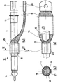
- a contact rod 10 of conductive material is formed by a cylindrical pin 12 comprising a first contact element 14 at one of its ends, and a second element contact 17 at the opposite end.
- Each contact element 14, 17 can be equipped with a racking-in clamp (not shown) capable of cooperating with a fixed conjugate contact.
- a contact rod control member 10 is coupled to a stop ring 16 integral with the pin 12 to ensure the displacement in axial translation of the contact rod 10.
- the electrical connection of the movable spindle 12 with a fixed track takes place by means of a flexible conductor formed by a braid 18.
- One of the ends of the braid 18 is capped by a connection terminal 20 to the beach.
- the other end 21 of the braid 18 is connected to the pin 12 along an intermediate zone extending over a fraction of the axial length provided between the first contact element 14 and the ring 16 of the control member .
- the braid 18 is shaped as a flattened sheath composed of strands intertwined into conductive wires and comprising a radial orifice 22 for introducing the pin 12. Between the orifice 22 and the terminal 20, the braid 18 is flat, and is located on the same side of the pin 12. Between the orifice 22 and the end 21, the braid 12 is tubular and coaxially surrounds the cylindrical lateral surface of the pin 12 in the intermediate connection zone in which an outer sleeve 24 of fixing is secured by crimping to the pin 12 by trapping the tubular portion of the braid 18.
- the sleeve 24 of conductive metallic material has a polygonal section, but any other shape, in particular circular or oval, can be used.
- the bearing surface 26 coming into contact with the tubular portion of the braid 18 has a narrowed circular section whose diameter is slightly less than that of the spindle 12.
- the cylindrical bearing surface 26 is smooth, or can be equipped with gripping means, in particular roughness or drainage, intended to improve the mechanical resistance in rotation and in translation of the braid 18 when the Sleeve 24 is tightened.
- the coaxial arrangement of the braid 18 around the pin 12 makes it possible to obtain an annular contact surface (FIG. 3) allowing a uniform distribution of the electric field and good dielectric strength of the apparatus. This also results in a minimum radial size at the connection thanks to the small thickness of the fixing sleeve 24.
Landscapes
- Connections Effected By Soldering, Adhesion, Or Permanent Deformation (AREA)
- Multi-Conductor Connections (AREA)
- Cable Accessories (AREA)
- Non-Insulated Conductors (AREA)
- Coupling Device And Connection With Printed Circuit (AREA)
- Manufacturing Of Electrical Connectors (AREA)
- Manufacture Of Switches (AREA)
- Driving Mechanisms And Operating Circuits Of Arc-Extinguishing High-Tension Switches (AREA)
- Contacts (AREA)
- Mutual Connection Of Rods And Tubes (AREA)
- Processing Of Terminals (AREA)
Priority Applications (1)
| Application Number | Priority Date | Filing Date | Title |
|---|---|---|---|
| AT84402424T ATE32640T1 (de) | 1983-12-09 | 1984-11-28 | Verbindungsvorrichtung einer beflechtung an einem kontaktstab und montageverfahren. |
Applications Claiming Priority (2)
| Application Number | Priority Date | Filing Date | Title |
|---|---|---|---|
| FR8319896A FR2556511B1 (fr) | 1983-12-09 | 1983-12-09 | Dispositif de raccordement d'une tresse de liaison a une tige de contact, et son procede d'assemblage |
| FR8319896 | 1983-12-09 |
Publications (2)
| Publication Number | Publication Date |
|---|---|
| EP0163794A1 true EP0163794A1 (de) | 1985-12-11 |
| EP0163794B1 EP0163794B1 (de) | 1988-02-24 |
Family
ID=9295104
Family Applications (1)
| Application Number | Title | Priority Date | Filing Date |
|---|---|---|---|
| EP84402424A Expired EP0163794B1 (de) | 1983-12-09 | 1984-11-28 | Verbindungsvorrichtung einer Beflechtung an einem Kontaktstab und Montageverfahren |
Country Status (8)
| Country | Link |
|---|---|
| EP (1) | EP0163794B1 (de) |
| JP (1) | JPS60140610A (de) |
| AT (1) | ATE32640T1 (de) |
| AU (1) | AU572910B2 (de) |
| DE (1) | DE3469471D1 (de) |
| FR (1) | FR2556511B1 (de) |
| IN (1) | IN163296B (de) |
| ZA (1) | ZA849541B (de) |
Cited By (2)
| Publication number | Priority date | Publication date | Assignee | Title |
|---|---|---|---|---|
| CN108879121A (zh) * | 2018-07-04 | 2018-11-23 | 潘红英 | 一种电力施工用接线头加固装置 |
| CN110544860A (zh) * | 2019-09-26 | 2019-12-06 | 东莞市锐华自动化设备有限公司 | 连接线整平装置及其方法 |
Families Citing this family (2)
| Publication number | Priority date | Publication date | Assignee | Title |
|---|---|---|---|---|
| FR2774210B1 (fr) * | 1998-01-27 | 2000-03-17 | Schneider Electric Ind Sa | Piece de contact mobile pour un disjoncteur a haute tension, et a auto-expansion |
| US9570826B2 (en) * | 2014-12-08 | 2017-02-14 | Eaton Corporation | Connection apparatus usable in vacuum interrupter |
Citations (3)
| Publication number | Priority date | Publication date | Assignee | Title |
|---|---|---|---|---|
| US1759767A (en) * | 1926-01-14 | 1930-05-20 | Gen Electric | Liquid-lever gauge for boilers |
| US2012536A (en) * | 1933-11-17 | 1935-08-27 | Herbert G Honig | Cable bond |
| US3315024A (en) * | 1964-11-19 | 1967-04-18 | Thomas & Betts Corp | Grounding sheath connector |
Family Cites Families (1)
| Publication number | Priority date | Publication date | Assignee | Title |
|---|---|---|---|---|
| US1759567A (en) * | 1928-09-07 | 1930-05-20 | Dibner Abraham Bernard | Slide joint for electrical conductors |
-
1983
- 1983-12-09 FR FR8319896A patent/FR2556511B1/fr not_active Expired
-
1984
- 1984-11-28 DE DE8484402424T patent/DE3469471D1/de not_active Expired
- 1984-11-28 AT AT84402424T patent/ATE32640T1/de not_active IP Right Cessation
- 1984-11-28 EP EP84402424A patent/EP0163794B1/de not_active Expired
- 1984-12-06 IN IN962/MAS/84A patent/IN163296B/en unknown
- 1984-12-07 AU AU36428/84A patent/AU572910B2/en not_active Ceased
- 1984-12-07 ZA ZA849541A patent/ZA849541B/xx unknown
- 1984-12-08 JP JP59259860A patent/JPS60140610A/ja active Granted
Patent Citations (3)
| Publication number | Priority date | Publication date | Assignee | Title |
|---|---|---|---|---|
| US1759767A (en) * | 1926-01-14 | 1930-05-20 | Gen Electric | Liquid-lever gauge for boilers |
| US2012536A (en) * | 1933-11-17 | 1935-08-27 | Herbert G Honig | Cable bond |
| US3315024A (en) * | 1964-11-19 | 1967-04-18 | Thomas & Betts Corp | Grounding sheath connector |
Cited By (2)
| Publication number | Priority date | Publication date | Assignee | Title |
|---|---|---|---|---|
| CN108879121A (zh) * | 2018-07-04 | 2018-11-23 | 潘红英 | 一种电力施工用接线头加固装置 |
| CN110544860A (zh) * | 2019-09-26 | 2019-12-06 | 东莞市锐华自动化设备有限公司 | 连接线整平装置及其方法 |
Also Published As
| Publication number | Publication date |
|---|---|
| JPS60140610A (ja) | 1985-07-25 |
| FR2556511B1 (fr) | 1986-08-01 |
| ZA849541B (en) | 1985-07-31 |
| ATE32640T1 (de) | 1988-03-15 |
| EP0163794B1 (de) | 1988-02-24 |
| IN163296B (de) | 1988-09-03 |
| JPH0471283B2 (de) | 1992-11-13 |
| AU3642884A (en) | 1985-06-13 |
| FR2556511A1 (fr) | 1985-06-14 |
| AU572910B2 (en) | 1988-05-19 |
| DE3469471D1 (en) | 1988-03-31 |
Similar Documents
| Publication | Publication Date | Title |
|---|---|---|
| EP0644631B1 (de) | Kollektor für Wechselstromgenerator hauptsächlich für Kraftfahrzeuge | |
| EP1054479A1 (de) | Anordnung für eine elektrische Verbindung zwischen einer koaxialen Leitung und einer gedrückten Schaltungskarte | |
| EP0644630B1 (de) | Kollektor für einen Wechselstromgenerator, insbesondere für ein Kraftfahrzeug | |
| FR2912000A1 (fr) | Cable de raccordement de poles de batterie | |
| EP0271413A1 (de) | Isolationsverschiebungssteckverbinder für Einzelleiterkabel | |
| EP0308845A1 (de) | Elektrische Drahtabzweigungsklemme ohne vorheriges Isolationsabziehen | |
| EP0163794B1 (de) | Verbindungsvorrichtung einer Beflechtung an einem Kontaktstab und Montageverfahren | |
| FR2899389A1 (fr) | Terminaison de connexion d'un cable supraconducteur | |
| FR2782194A1 (fr) | Dispositif de connexion auto-denudant | |
| EP0130923B1 (de) | Verfahren zur Herstellung einer Verbindung zwischen Supraleitern | |
| EP1432073A1 (de) | Koaxiale kolineare Antenne | |
| FR2627638A1 (fr) | Ensemble connecteur de mise a la masse pour cable de branchement | |
| FR2758661A1 (fr) | Dispositif de raccordement mecanique et de connexion electrique | |
| EP0308847B1 (de) | Magnetische Blasspule mit Lichtbogenrotation für Schaltelement eines elektrischen Schalters | |
| EP0669677B1 (de) | Elektrische Verbinderanordnung für leitende Kabelabschirmung und Verfahren zu ihrer Ausführung | |
| FR2958807A1 (fr) | Dispositif de connexion de deux cables supraconducteurs | |
| FR2844926A1 (fr) | Dispositif de fixation et de contact pour barres de bus | |
| EP0860899B1 (de) | Isolations-Perforierverbinder | |
| FR2584246A1 (fr) | Disposition de fils de bobinage dans les encoches d'un induit d'une machine a courant continu | |
| FR2767959A1 (fr) | Dispositif passe-tige et ensemble passe-tige le comportant | |
| FR2591393A1 (fr) | Procede pour fixer a une plante de support un conducteur electrique et application du procede a la realisation de dispositifs de detection d'usure de garnitures de friction | |
| FR2679074A1 (fr) | Conducteur de metallisation pour la realisation de liaisons assurant une continuite electrique entre pieces mecaniques. | |
| EP1650831B1 (de) | Kabelschuh für eine elektrische Verbindung mit einem verjüngten Abschnitt | |
| FR2751474A1 (fr) | Dispositif de raccordement a conducteur monobrin | |
| FR2492579A1 (fr) | Contact pour appareillage electrique, tel que disjoncteur |
Legal Events
| Date | Code | Title | Description |
|---|---|---|---|
| PUAI | Public reference made under article 153(3) epc to a published international application that has entered the european phase |
Free format text: ORIGINAL CODE: 0009012 |
|
| AK | Designated contracting states |
Designated state(s): AT BE CH DE GB IT LI NL SE |
|
| 17P | Request for examination filed |
Effective date: 19860421 |
|
| 17Q | First examination report despatched |
Effective date: 19870309 |
|
| ITF | It: translation for a ep patent filed | ||
| GRAA | (expected) grant |
Free format text: ORIGINAL CODE: 0009210 |
|
| AK | Designated contracting states |
Kind code of ref document: B1 Designated state(s): AT BE CH DE GB IT LI NL SE |
|
| REF | Corresponds to: |
Ref document number: 32640 Country of ref document: AT Date of ref document: 19880315 Kind code of ref document: T |
|
| REF | Corresponds to: |
Ref document number: 3469471 Country of ref document: DE Date of ref document: 19880331 |
|
| GBT | Gb: translation of ep patent filed (gb section 77(6)(a)/1977) | ||
| PLBE | No opposition filed within time limit |
Free format text: ORIGINAL CODE: 0009261 |
|
| STAA | Information on the status of an ep patent application or granted ep patent |
Free format text: STATUS: NO OPPOSITION FILED WITHIN TIME LIMIT |
|
| 26N | No opposition filed | ||
| ITTA | It: last paid annual fee | ||
| PGFP | Annual fee paid to national office [announced via postgrant information from national office to epo] |
Ref country code: NL Payment date: 19921130 Year of fee payment: 9 |
|
| PGFP | Annual fee paid to national office [announced via postgrant information from national office to epo] |
Ref country code: AT Payment date: 19931112 Year of fee payment: 10 |
|
| PG25 | Lapsed in a contracting state [announced via postgrant information from national office to epo] |
Ref country code: NL Effective date: 19940601 |
|
| NLV4 | Nl: lapsed or anulled due to non-payment of the annual fee | ||
| PG25 | Lapsed in a contracting state [announced via postgrant information from national office to epo] |
Ref country code: AT Effective date: 19941128 |
|
| EAL | Se: european patent in force in sweden |
Ref document number: 84402424.0 |
|
| PGFP | Annual fee paid to national office [announced via postgrant information from national office to epo] |
Ref country code: CH Payment date: 19951211 Year of fee payment: 12 |
|
| PGFP | Annual fee paid to national office [announced via postgrant information from national office to epo] |
Ref country code: BE Payment date: 19960109 Year of fee payment: 12 |
|
| PGFP | Annual fee paid to national office [announced via postgrant information from national office to epo] |
Ref country code: GB Payment date: 19961119 Year of fee payment: 13 |
|
| PG25 | Lapsed in a contracting state [announced via postgrant information from national office to epo] |
Ref country code: LI Effective date: 19961130 Ref country code: CH Effective date: 19961130 Ref country code: BE Effective date: 19961130 |
|
| BERE | Be: lapsed |
Owner name: MERLIN GERIN Effective date: 19961130 |
|
| REG | Reference to a national code |
Ref country code: CH Ref legal event code: PL |
|
| PG25 | Lapsed in a contracting state [announced via postgrant information from national office to epo] |
Ref country code: GB Free format text: LAPSE BECAUSE OF NON-PAYMENT OF DUE FEES Effective date: 19971128 |
|
| GBPC | Gb: european patent ceased through non-payment of renewal fee |
Effective date: 19971128 |
|
| PGFP | Annual fee paid to national office [announced via postgrant information from national office to epo] |
Ref country code: SE Payment date: 19981105 Year of fee payment: 15 |
|
| PGFP | Annual fee paid to national office [announced via postgrant information from national office to epo] |
Ref country code: DE Payment date: 19981106 Year of fee payment: 15 |
|
| PG25 | Lapsed in a contracting state [announced via postgrant information from national office to epo] |
Ref country code: SE Free format text: LAPSE BECAUSE OF NON-PAYMENT OF DUE FEES Effective date: 19991129 |
|
| EUG | Se: european patent has lapsed |
Ref document number: 84402424.0 |
|
| PG25 | Lapsed in a contracting state [announced via postgrant information from national office to epo] |
Ref country code: DE Free format text: LAPSE BECAUSE OF NON-PAYMENT OF DUE FEES Effective date: 20000901 |