EP0163797B1 - Selbständige Lüfterkupplung - Google Patents
Selbständige Lüfterkupplung Download PDFInfo
- Publication number
- EP0163797B1 EP0163797B1 EP84630089A EP84630089A EP0163797B1 EP 0163797 B1 EP0163797 B1 EP 0163797B1 EP 84630089 A EP84630089 A EP 84630089A EP 84630089 A EP84630089 A EP 84630089A EP 0163797 B1 EP0163797 B1 EP 0163797B1
- Authority
- EP
- European Patent Office
- Prior art keywords
- pressure cavity
- cavity side
- clutch
- fluid passage
- pump
- Prior art date
- Legal status (The legal status is an assumption and is not a legal conclusion. Google has not performed a legal analysis and makes no representation as to the accuracy of the status listed.)
- Expired
Links
- 239000012530 fluid Substances 0.000 claims description 42
- 238000005086 pumping Methods 0.000 claims description 3
- 239000006187 pill Substances 0.000 description 17
- 230000033001 locomotion Effects 0.000 description 5
- 230000008878 coupling Effects 0.000 description 3
- 238000010168 coupling process Methods 0.000 description 3
- 238000005859 coupling reaction Methods 0.000 description 3
- 230000002093 peripheral effect Effects 0.000 description 3
- 238000007789 sealing Methods 0.000 description 3
- 230000005540 biological transmission Effects 0.000 description 2
- 238000001816 cooling Methods 0.000 description 2
- 229910000906 Bronze Inorganic materials 0.000 description 1
- 239000010974 bronze Substances 0.000 description 1
- KUNSUQLRTQLHQQ-UHFFFAOYSA-N copper tin Chemical compound [Cu].[Sn] KUNSUQLRTQLHQQ-UHFFFAOYSA-N 0.000 description 1
- 238000009877 rendering Methods 0.000 description 1
Images

Classifications
-
- F—MECHANICAL ENGINEERING; LIGHTING; HEATING; WEAPONS; BLASTING
- F16—ENGINEERING ELEMENTS AND UNITS; GENERAL MEASURES FOR PRODUCING AND MAINTAINING EFFECTIVE FUNCTIONING OF MACHINES OR INSTALLATIONS; THERMAL INSULATION IN GENERAL
- F16D—COUPLINGS FOR TRANSMITTING ROTATION; CLUTCHES; BRAKES
- F16D43/00—Automatic clutches
- F16D43/28—Automatic clutches actuated by fluid pressure
-
- F—MECHANICAL ENGINEERING; LIGHTING; HEATING; WEAPONS; BLASTING
- F16—ENGINEERING ELEMENTS AND UNITS; GENERAL MEASURES FOR PRODUCING AND MAINTAINING EFFECTIVE FUNCTIONING OF MACHINES OR INSTALLATIONS; THERMAL INSULATION IN GENERAL
- F16D—COUPLINGS FOR TRANSMITTING ROTATION; CLUTCHES; BRAKES
- F16D43/00—Automatic clutches
- F16D43/02—Automatic clutches actuated entirely mechanically
- F16D43/25—Automatic clutches actuated entirely mechanically controlled by thermo-responsive elements
Definitions
- the invention relates broadly to self-contained clutches having no external controls and more particularly to a fan clutch mounted on a drive shaft for intermittent cooling of an engine.
- a known self-contained clutch of this type is exemplified by GB-A-2 036 202 which discloses a self-contained clutch having no external controls comprising, in combination: a first member; a second member rotatably mounted with respect to the first member; a drive disc for rotation with the first member; a piston mounted for reciprocation within a cylinder carried by the second member, friction facing means engaged by the piston for engagement contact with the drive disc for providing rotation of the second member with the first member; an environment sensing means carried by the second member for moving the piston within the cylinder to cause the friction facing to engage and disengage with the drive disc so that when the condition of the environment sensed by the environment sensing means is within a first range, the friction facing is disengaged from the drive disc and thus the first and second members are not rotatably interrelated but when the condition of the environment sensed by the environment sensing means is within a second range, the friction facing is engaged with the drive disc and the first and second members are rotatably interrelated.
- Known self-contained clutches modulate, that is, the amount of power transmission is proportional to the ambient temperature.
- the object of the present invention is to provide a self-contained clutch of the above type which is either totally “on” or totally “off” depending upon the selected temperature for operation or non-operation of the clutch and does not suffer of the mentioned disadvantages of the prior art clutches of this type.
- the self-contained clutch of the invention is characterized by the features claimed in the characterizing portion of independent claim 1.
- the system disclosed does not modulate because there is a selected temperature for closure and opening by means of a first thermal sensor controlling a bypass check valve which either allows pressure to be pumped up or fluid to be bypassed from a high pressure cavity on one side of a piston carrying a friction facing.
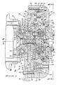
- the self-contained fan clutch A includes the circular mounting plate 10 secured to the coupling B by means of the bolts 12, the coupling connected to a live shaft not shown.
- the hub 14 having splines 16 thereon in engagement with splines 18 of the hub 20 of the driven drive disc 22 having the flat central portion 24 which terminates radially in the offset portion 26 which in turn terminates in the outer flange portion 28.
- the hub 14 is formed with the recess 30 and the hub 20 is formed with the recess 32 with the inner race 34 of the bearing 36 clamped between the shoulders of the recesses 30 and 32.
- the numeral 38 designates a first outer housing section which includes the hub portion 40 from which radially extends the flat central portion 42. The portion 42 terminates in the offset portion 44.
- the hub portion 40 has formed therein the recess 46 in which is press fit the outer race 48 of the bearing 36 whereby the first housing section 38 is rotatably mounted on the hubs 14 and 20. Secured to the first housing section 38 by means of bolts 39, are a multiplicity of fan blades 49.
- the end portion 50 of the hub 14 is formed with the hole 52 through which extends the bolt 54 which threadedly engages the axial opening 56 of the portion 24 of the disc 22 and the extension 58 thereof.
- the driven cam 60 Secured to the inner face of the portion 24 of the disc 22 is the driven cam 60 by means of the bolts 61 and extending through the cam is the central opening 59 through which the extension 58 extends.
- the numeral 62 designates a second outer housing section which includes the flat circular face portion 64 which terminates in the outer J eripheral flange portion 67.
- Formed on the inner surface of the portion 64 of the housing portion 62 is the annular shoulder 66 a portion of which forms an annular cylinder wall on the outer periphery of which is formed the groove 68 and in which is positioned the 0-ring 70.
- annular cylinder member 72 having the central and axial extension portion 75 from which extends the outer peripheral flange portion 74 which has formed in the outer edge thereof the recess 76 in which is positioned the 0-ring 78.
- the numeral 80 designates an annular piston having the central annular portion 82 normal to the radial axis of the portion 82 and from which radially and outwardly extends the annular portion 84.
- the 0-ring 70 has sealing contact with the piston annular portion 82.
- Secured to the piston portion 84 is the friction facing ring 86 by means of spaced bolts 88.
- annular piston flange portion 90 Extending radially inwardly from the central annular portion 82 of the piston 80 is the annular piston flange portion 90 on the inner edge of which is formed the recess 92 in which is positioned the O-ring 94 having sealing contact with extension 75.
- the flange 90 is positioned between the flange portion 66 of the second housing portion 62 and the flange 74 of the cylinder member 72 for slideable movement therebetween in a cylinder cavity C formed between the flange 66 and the flange portion 74.
- the piston flange 90 is sealed by the 0-ring 70, 78, and 94.
- the cylinder cavity C is divided into two parts, the low pressure side Ca and the high pressure side Cb, by the piston flange 90.
- the axial recess 91 Formed in the center of the cylinder member 72 is the axial recess 91 in which is mounted the bronze support bushing 93 in which is positioned the extension 58 for relative rotation between the extension 58 and the bushing 93.
- the first cavity 96 Formed in the extension 75 of the cylinder member 72 is the first cavity 96 in which is slideably mounted a push plate 98, and mounted between the push plate 98 and the annular shoulder 100 of the cavity 96 is the coil spring 102, the confined length of which provides a minimum of a 10 lb. load between the shoulder 100 and the push plate 98.
- the conduits 95 and 97 which communicate with cavities hereinafter described, particularly Figures 3,4 and 5, Conduit 97 communicates with conduit 99.
- the numeral 104 designates a first conventional wax filled thermal pill screwed into the flange portion 66 with the step 106 extending into the recess 108 of the push plate 98.
- the push plate 98 has formed on the inner surface thereof the axial projection 110 which mounts the coil spring 112 the other end of which is mounted on a similar projection 114 mounted on the outer end of the cylindrical pump plunger 116 having the semispherical outer end 118 for contact with the cam 60.
- the pump plunger 116 reciprocates in the cylinder wall 113 with the plunger 116 having sealing engagement with the 0-ring 119 in the annular groove 121.
- the spring 112 provides a return force to the pump plunger as it reciprocates as hereinbefore described.
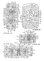
- a second receiver cavity 120 in which an insert sleeve 115 is press fit.
- the sleeve is spaced on the bottom of the cavity 120 to form a passageway 117 which communicates with a transversely directed conduit 117a, which in turn connects with passageway 117b which connects with cavity Cb, Figures 1 and 5 in particular.
- Slideably mounted in the sleeve is a push plate 122 and mounted between the push plate 122 and the annular shoulder 124 of the sleeve 115 is the coil spring 127 the confined length of which provides a minimum of a 10 lb. load between the shoulder 124 and the push plate 122.
- the numeral 126 designates a second conventional wax filled thermal pill screwed into the flange portion 66 with the stem 128 extending into the recess of the second push plate 122.
- the push plate 122 has formed on the inner surface thereof the axial projection 132 which mounts the coil spring 134 the other end of which engages a conventional thermally controlled bypass check valve 136 having an 0-ring 138 which seals upon the valve seat 140 on conduit 141 as hereinafter described.
- the numeral 142 designates a third receiver cavity, Figure 2, in which is press fit an insert sleeve 144 in itself having a cavity 146 the inner end of which terminates in the conduit 148. At the juncture of the cavity and the conduit is the valve seat 150. Further provided is the suction side poppet valve 152 having the shoulder 154 from which extends the stem 156. A coil spring 158 is positioned on the stem 156 and between the shoulder 154 and the inner face of the outer peripheral flange portion 66 normaly urging the valve 152 to a closed position.
- the sleeve 144 is spaced from the bottom of the cavity 142 to form a passageway 160 interconnecting with the conduit 148 and hole 162 which communicates with cylinder cavity part Ca. Leading from the passageway 160 is the conduit 164 which connects with the fluid reservoir 166.
- the numeral 168 designates a fourth receiver cavity in which is press fit an insert sleeve 170 in itself having a cavity 172 the inner end of which terminates in the conduit 174. Atthe juncture of the cavity 172 and the conduit 174 is the valve seat 176. Further provided is the pressure side poppet valve 178 having the shoulder 180 from which extends the stem 182. A coil spring 184 is positioned on the stem 182 and between the shoulder 180 and the innerface of the outer peripheral flange portion 66 normally urging the valve 178 to a closed position.
- the sleeve 170 is spaced from the bottom of the cavity 168 to form a passageway 186 which communicates with conduit 99 at substantially a right angle, particularly Figures 3 and 4.
- Cavity 172 communicates with conduit 173 which communicates with conduit 164 and thence to high pressure cylinder cavity Cb.
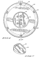
- a plurality of spaced torque bolts 198 are provided each of which is secured at one end in the portion 64 of the second outer housing 62 with the other end slideably mounted in the sleeve 200 mounted in the annular portion 84 of the piston 80.
- thermal wax pill 126 was also heated along with pill 104 and as a result, the valve 136 is maintained in a closed position thereby checking fluid flow from the reservoir 166 through conduit 117a i.e. the high side of the reservoir.
- the piston pump cannot draw from the high side of the reservoir when the unit is hot because the check valve 136 is held closed.
- the pill temperature recedes.
- the pill 126 causes the bypass valve 136 to recede whereby high fluid pressure is shunted to the low pressure side Ca through conduits 141, 117a, reservoir 166, 164, 160 and 162, thereby causing the piston 80 to shift to the high side Cb by reason of the springs 190.
Landscapes
- Engineering & Computer Science (AREA)
- General Engineering & Computer Science (AREA)
- Mechanical Engineering (AREA)
- Physics & Mathematics (AREA)
- Fluid Mechanics (AREA)
- Hydraulic Clutches, Magnetic Clutches, Fluid Clutches, And Fluid Joints (AREA)
Claims (13)
Priority Applications (3)
| Application Number | Priority Date | Filing Date | Title |
|---|---|---|---|
| US06/401,591 US4456110A (en) | 1980-10-11 | 1982-07-26 | Self-contained fan clutch |
| DE8484630089T DE3473329D1 (en) | 1984-06-05 | 1984-06-05 | Self-contained fan clutch |
| EP84630089A EP0163797B1 (de) | 1980-10-11 | 1984-06-05 | Selbständige Lüfterkupplung |
Applications Claiming Priority (3)
| Application Number | Priority Date | Filing Date | Title |
|---|---|---|---|
| US20561980A | 1980-10-11 | 1980-10-11 | |
| US06/401,591 US4456110A (en) | 1980-10-11 | 1982-07-26 | Self-contained fan clutch |
| EP84630089A EP0163797B1 (de) | 1980-10-11 | 1984-06-05 | Selbständige Lüfterkupplung |
Publications (2)
| Publication Number | Publication Date |
|---|---|
| EP0163797A1 EP0163797A1 (de) | 1985-12-11 |
| EP0163797B1 true EP0163797B1 (de) | 1988-08-10 |
Family
ID=27227431
Family Applications (1)
| Application Number | Title | Priority Date | Filing Date |
|---|---|---|---|
| EP84630089A Expired EP0163797B1 (de) | 1980-10-11 | 1984-06-05 | Selbständige Lüfterkupplung |
Country Status (2)
| Country | Link |
|---|---|
| US (1) | US4456110A (de) |
| EP (1) | EP0163797B1 (de) |
Families Citing this family (25)
| Publication number | Priority date | Publication date | Assignee | Title |
|---|---|---|---|---|
| US4456110A (en) * | 1980-10-11 | 1984-06-26 | Horton Industries, Inc. | Self-contained fan clutch |
| US4564095A (en) * | 1984-01-23 | 1986-01-14 | Febco Inc. | Friction-less hydraulic clutch device |
| EP0229436A1 (de) * | 1986-01-07 | 1987-07-22 | Febco Inc. | Reibungsfreie hydraulische Kupplungseinrichtung |
| JPS62155339A (ja) * | 1985-12-26 | 1987-07-10 | Toyota Central Res & Dev Lab Inc | 回転トルク伝達接手 |
| SE460551B (sv) * | 1987-06-25 | 1989-10-23 | Sigvard Johansson | Anordning foer att motverka relativ rotationsroerelse mellan tvaa roterbara axlar |
| IT1247230B (it) * | 1991-01-21 | 1994-12-12 | Carraro Spa | Meccanismo ad azionamento idraulico per il comando di un innesto per organi rotanti,in particolare per l`innesto del bloccaggio di un differenziale. |
| US5398794A (en) * | 1993-06-02 | 1995-03-21 | Horton Industries, Inc. | Overheating protection device for rotational control apparatus |
| US5667045A (en) * | 1995-09-18 | 1997-09-16 | Rockford Powertrain, Inc. | Continuously variable fan drive clutch arrangement |
| US5937979A (en) * | 1995-09-18 | 1999-08-17 | Rockford Powertrain, Inc. | Continuosly variable fan drive clutch |
| US5947247A (en) * | 1995-09-18 | 1999-09-07 | Rockford Powertrain, Inc. | Continuously variable fan drive clutch |
| US5855266A (en) * | 1995-09-18 | 1999-01-05 | Rockford Powertrain, Inc. | Fan clutch for vehicles configured for low engine speed |
| JP3807585B2 (ja) | 1999-05-17 | 2006-08-09 | 株式会社ユニバンス | 油圧式動力伝達継手のドレーン機構 |
| JP3807586B2 (ja) * | 1999-05-28 | 2006-08-09 | 株式会社ユニバンス | 油圧式動力伝達継手 |
| US6651794B2 (en) * | 2001-12-07 | 2003-11-25 | Caterpillar Inc | Hydro-mechanical combiner |
| US7438169B2 (en) | 2004-10-21 | 2008-10-21 | Kit Masters Inc. | Clutch system |
| US7104382B2 (en) * | 2004-10-21 | 2006-09-12 | Kit Masters Inc. | Clutch system |
| AT501067A1 (de) * | 2004-11-19 | 2006-06-15 | Man Nutzfahrzeuge Oesterreich | Schaltbare kupplungsanordnung zur ankopplung eines nebenaggregates |
| US7100544B1 (en) | 2005-07-29 | 2006-09-05 | Borgwarner Inc. | Pneumatic cone clutch fan drive having threaded attachment method for drive shaft of clutch to hub mounting |
| EP2122190A1 (de) * | 2006-12-22 | 2009-11-25 | Borgwarner, Inc. | Mechanisches schlupfschutzsystem für hochleistungslüfterkupplung mit mehreren gescwindigkeiten |
| US8100239B2 (en) * | 2008-01-18 | 2012-01-24 | Kit Masters Inc. | Clutch device and methods |
| WO2009114317A2 (en) * | 2008-03-12 | 2009-09-17 | Borgwarner Inc. | Cooling system for clutch |
| WO2010056830A2 (en) * | 2008-11-12 | 2010-05-20 | Horton, Inc. | Two-speed clutch and retro-fit kit |
| US8109375B2 (en) * | 2009-05-07 | 2012-02-07 | Kit Masters Inc. | Clutch systems and methods |
| US9046137B2 (en) | 2010-01-22 | 2015-06-02 | Kit Masters Inc. | Fan clutch apparatus and methods |
| US8360219B2 (en) | 2010-04-26 | 2013-01-29 | Kit Masters, Inc. | Clutch system and methods |
Family Cites Families (15)
| Publication number | Priority date | Publication date | Assignee | Title |
|---|---|---|---|---|
| GB1053251A (de) * | 1900-01-01 | |||
| US1882807A (en) * | 1929-06-10 | 1932-10-18 | Gillett Edward Henry Jam Cecil | Transmission system |
| US2153372A (en) * | 1938-07-19 | 1939-04-04 | Walter Bold | Automatic hydraulic clutch |
| US2876881A (en) * | 1957-04-15 | 1959-03-10 | Lambert & Brake Corp | Automatic self-adjusting clutch |
| US3207279A (en) * | 1959-10-30 | 1965-09-21 | Srm Svenska Rotor Maskiner Ab | Fluid and mechanical clutches |
| US3488980A (en) * | 1968-05-29 | 1970-01-13 | Deere & Co | Torque limiting clutch |
| GB1592604A (en) * | 1977-03-07 | 1981-07-08 | Holset Engineering Co | Clutch assemblies |
| US4238017A (en) * | 1977-12-05 | 1980-12-09 | Borg-Warner Corporation | Clutch mechanism |
| GB2036202A (en) * | 1978-10-20 | 1980-06-25 | Task Power & Control Ltd | Fan drive |
| US4304321A (en) * | 1979-01-18 | 1981-12-08 | Standard-Thomson Corporation | Thermally responsive actuator device particularly for automotive fan clutch |
| AU5412379A (en) * | 1979-02-01 | 1980-08-07 | Thomson International Corp. | Thermally responsive actuator device particularly for automotive fan clutch |
| US4355710A (en) * | 1980-08-25 | 1982-10-26 | Horton Industries, Inc. | Spring engaged fluid released fan clutch for a live shaft |
| US4456110A (en) * | 1980-10-11 | 1984-06-26 | Horton Industries, Inc. | Self-contained fan clutch |
| US4408685A (en) * | 1980-11-13 | 1983-10-11 | Horton Industries, Inc. | Fluid set and spring released clutch |
| US4339507A (en) * | 1980-11-26 | 1982-07-13 | Union Carbide Corporation | Linear low density ethylene hydrocarbon copolymer containing composition for extrusion coating |
-
1982
- 1982-07-26 US US06/401,591 patent/US4456110A/en not_active Expired - Lifetime
-
1984
- 1984-06-05 EP EP84630089A patent/EP0163797B1/de not_active Expired
Also Published As
| Publication number | Publication date |
|---|---|
| EP0163797A1 (de) | 1985-12-11 |
| US4456110A (en) | 1984-06-26 |
Similar Documents
| Publication | Publication Date | Title |
|---|---|---|
| EP0163797B1 (de) | Selbständige Lüfterkupplung | |
| CA1092918A (en) | Clutch mechanism for an engine accessory | |
| US3323623A (en) | Rotatable coupling device | |
| US6098771A (en) | Clutch with on-demand cooling | |
| CA1158189A (en) | Spring engaged fluid released fan clutch for a live shaft | |
| EP0015643A2 (de) | Flüssigkeitskupplung mit verbesserter Reaktionszeit | |
| EP0994268A2 (de) | Mehrzweck-Ventisteuerung für eine hydraulische Kupplung | |
| US3972399A (en) | Temperature responsive coupling | |
| US3253687A (en) | Fluid operated clutch | |
| JPH0361852B2 (de) | ||
| US3968866A (en) | Fluid coupling | |
| CA1099166A (en) | Clutch mechanism | |
| US3915269A (en) | Fan drive clutch and brake apparatus | |
| EP2935893B1 (de) | Vakuumpumpe mit einer trennbaren antriebskupplung | |
| JPH0469287B2 (de) | ||
| US3800930A (en) | Variable speed drive | |
| US7143884B2 (en) | Bi-directional clutch unit | |
| CA1184452A (en) | Self-contained fan clutch | |
| JP2881653B2 (ja) | トルク制限継手装置 | |
| WO1995035453A1 (en) | Pressure activated rotary clutch | |
| EP0197796A1 (de) | Flüssigkeitsgetriebe | |
| CA1065187A (en) | Impeller pump and vane pump assembly with clutch deactivation | |
| USRE30608E (en) | Temperature responsive coupling | |
| US2913083A (en) | Hydraulic fan drives | |
| JP4049952B2 (ja) | トルクリミッタ |
Legal Events
| Date | Code | Title | Description |
|---|---|---|---|
| PUAI | Public reference made under article 153(3) epc to a published international application that has entered the european phase |
Free format text: ORIGINAL CODE: 0009012 |
|
| 17P | Request for examination filed |
Effective date: 19841228 |
|
| AK | Designated contracting states |
Designated state(s): BE DE FR GB IT SE |
|
| 17Q | First examination report despatched |
Effective date: 19861009 |
|
| D17Q | First examination report despatched (deleted) | ||
| GRAA | (expected) grant |
Free format text: ORIGINAL CODE: 0009210 |
|
| AK | Designated contracting states |
Kind code of ref document: B1 Designated state(s): BE DE FR GB IT SE |
|
| PG25 | Lapsed in a contracting state [announced via postgrant information from national office to epo] |
Ref country code: SE Effective date: 19880810 Ref country code: IT Free format text: LAPSE BECAUSE OF FAILURE TO SUBMIT A TRANSLATION OF THE DESCRIPTION OR TO PAY THE FEE WITHIN THE PRESCRIBED TIME-LIMIT;WARNING: LAPSES OF ITALIAN PATENTS WITH EFFECTIVE DATE BEFORE 2007 MAY HAVE OCCURRED AT ANY TIME BEFORE 2007. THE CORRECT EFFECTIVE DATE MAY BE DIFFERENT FROM THE ONE RECORDED. Effective date: 19880810 Ref country code: FR Free format text: THE PATENT HAS BEEN ANNULLED BY A DECISION OF A NATIONAL AUTHORITY Effective date: 19880810 Ref country code: BE Effective date: 19880810 |
|
| REF | Corresponds to: |
Ref document number: 3473329 Country of ref document: DE Date of ref document: 19880915 |
|
| EN | Fr: translation not filed | ||
| PLBE | No opposition filed within time limit |
Free format text: ORIGINAL CODE: 0009261 |
|
| STAA | Information on the status of an ep patent application or granted ep patent |
Free format text: STATUS: NO OPPOSITION FILED WITHIN TIME LIMIT |
|
| 26N | No opposition filed | ||
| PGFP | Annual fee paid to national office [announced via postgrant information from national office to epo] |
Ref country code: GB Payment date: 19910515 Year of fee payment: 8 |
|
| PGFP | Annual fee paid to national office [announced via postgrant information from national office to epo] |
Ref country code: DE Payment date: 19910530 Year of fee payment: 8 |
|
| PG25 | Lapsed in a contracting state [announced via postgrant information from national office to epo] |
Ref country code: GB Effective date: 19920605 |
|
| GBPC | Gb: european patent ceased through non-payment of renewal fee |
Effective date: 19920605 |
|
| PG25 | Lapsed in a contracting state [announced via postgrant information from national office to epo] |
Ref country code: DE Effective date: 19930302 |