EP0163807B1 - Système de vidéo domestique avec décodeur de télétexte - Google Patents
Système de vidéo domestique avec décodeur de télétexte Download PDFInfo
- Publication number
- EP0163807B1 EP0163807B1 EP85100987A EP85100987A EP0163807B1 EP 0163807 B1 EP0163807 B1 EP 0163807B1 EP 85100987 A EP85100987 A EP 85100987A EP 85100987 A EP85100987 A EP 85100987A EP 0163807 B1 EP0163807 B1 EP 0163807B1
- Authority
- EP
- European Patent Office
- Prior art keywords
- teletext
- signal
- recording
- supplied
- switch
- Prior art date
- Legal status (The legal status is an assumption and is not a legal conclusion. Google has not performed a legal analysis and makes no representation as to the accuracy of the status listed.)
- Expired
Links
- 239000002131 composite material Substances 0.000 claims abstract description 13
- 230000008878 coupling Effects 0.000 claims abstract description 13
- 238000010168 coupling process Methods 0.000 claims abstract description 13
- 238000005859 coupling reaction Methods 0.000 claims abstract description 13
- 239000003381 stabilizer Substances 0.000 description 5
- 230000001360 synchronised effect Effects 0.000 description 4
- 238000011161 development Methods 0.000 description 3
- 230000018109 developmental process Effects 0.000 description 3
- 239000000203 mixture Substances 0.000 description 3
- 238000000034 method Methods 0.000 description 2
- 208000032041 Hearing impaired Diseases 0.000 description 1
- 230000002452 interceptive effect Effects 0.000 description 1
- 229910000679 solder Inorganic materials 0.000 description 1
Images

Classifications
-
- H—ELECTRICITY
- H04—ELECTRIC COMMUNICATION TECHNIQUE
- H04N—PICTORIAL COMMUNICATION, e.g. TELEVISION
- H04N21/00—Selective content distribution, e.g. interactive television or video on demand [VOD]
- H04N21/40—Client devices specifically adapted for the reception of or interaction with content, e.g. set-top-box [STB]; Operations thereof
- H04N21/47—End-user applications
- H04N21/488—Data services, e.g. news ticker
- H04N21/4888—Data services, e.g. news ticker for displaying teletext characters
-
- H—ELECTRICITY
- H04—ELECTRIC COMMUNICATION TECHNIQUE
- H04N—PICTORIAL COMMUNICATION, e.g. TELEVISION
- H04N21/00—Selective content distribution, e.g. interactive television or video on demand [VOD]
- H04N21/40—Client devices specifically adapted for the reception of or interaction with content, e.g. set-top-box [STB]; Operations thereof
- H04N21/47—End-user applications
-
- H—ELECTRICITY
- H04—ELECTRIC COMMUNICATION TECHNIQUE
- H04N—PICTORIAL COMMUNICATION, e.g. TELEVISION
- H04N5/00—Details of television systems
- H04N5/76—Television signal recording
- H04N5/765—Interface circuits between an apparatus for recording and another apparatus
- H04N5/775—Interface circuits between an apparatus for recording and another apparatus between a recording apparatus and a television receiver
-
- H—ELECTRICITY
- H04—ELECTRIC COMMUNICATION TECHNIQUE
- H04N—PICTORIAL COMMUNICATION, e.g. TELEVISION
- H04N5/00—Details of television systems
- H04N5/76—Television signal recording
- H04N5/91—Television signal processing therefor
- H04N5/92—Transformation of the television signal for recording, e.g. modulation, frequency changing; Inverse transformation for playback
- H04N5/9201—Transformation of the television signal for recording, e.g. modulation, frequency changing; Inverse transformation for playback involving the multiplexing of an additional signal and the video signal
- H04N5/9206—Transformation of the television signal for recording, e.g. modulation, frequency changing; Inverse transformation for playback involving the multiplexing of an additional signal and the video signal the additional signal being a character code signal
- H04N5/9207—Transformation of the television signal for recording, e.g. modulation, frequency changing; Inverse transformation for playback involving the multiplexing of an additional signal and the video signal the additional signal being a character code signal for teletext
Definitions
- the present invention relates to a video home system with a television receiver, a video recorder that can be connected to the AV socket of the television receiver and a teletext decoder connected to the television receiver, to which the composite signal containing the coded teletext signals and at least one supply voltage are supplied by the television receiver .
- a teletext decoder of the type mentioned in the preamble of claim 1 is known, for example, from the magazine "GRUNDIG Technical Information", 4 / 5-1980, pages 171-196. Since the structure and mode of operation of the known teletext decoder are important for the present invention, this is first explained in more detail with the aid of FIG. 1.
- the teletext decoder shown in FIG. 1 essentially consists of a video processor 1, a data processing circuit 2, a page memory 3, a character generator 4, a clock controller 5, a teletext remote control interface 6 and a voltage stabilizer 7.
- the known teletext decoder requires two voltages (12 V for the video processor and 5 V for the further circuits) which are derived from voltages E and M 'which are present in the television receiver and the CVBS signal which contains the coded teletext signals and is usually removed from the IF amplifier of the television receiver. These signals are present at inputs a and b and c of the teletext decoder.
- the teletext decoder receives via its input d signals from a remote control receiver, not shown, which are characteristic of the entered operating commands. These signals are processed in the teletext remote control interface 6 for the further circuits of the teletext decoder.
- the CVBS signal fed to the input c reaches a video processor 1 in which the digital text signals are separated and passed on to the data processing circuit 2.
- the data processing circuit 2 subjects the serial incoming data to a parity and Hamming code check, converts them into parallel data words and forwards these parallel data words to the page memory 3.
- the data words stored in the page memory 3 are finally fed to a character generator 4, which has the task of displaying the data words supplied to it as characters or graphics on the television receiver screen.
- a circuit 5 for clock control is provided which is synchronized with the FBAS signal via line M and, among other things, supplies the video processor 1 with a complete and standard-compliant synchronization signal.
- the voltages supplied to the teletext decoder via its inputs a and b are stabilized in a voltage stabilizer 7.
- the individual circuit parts of the teletext decoder are supplied with the voltages obtained at the outputs of the voltage stabilizer 7, which are, for example, + 5 V and + 12 V.
- the characters read from the memory of the character generator reach the RGB module of the connected color television receiver, which continues to have a blanking or blanking signal for blanking the behind via the output h of the teletext decoder the video scene section to be displayed is supplied. Furthermore, a teletext luminance signal can be taken from the character generator 4 and is available at the output i.
- the television receiver is synchronized via output j of the teletext decoder. In teletext mode, the video processor 1 outputs to the output j of the teletext decoder the standard-compliant synchronization signal generated by the clock controller 5 and supplied to the video processor 1 via the line L.
- the present invention has for its object to develop a video home system with a television receiver, a video recorder and a teletext decoder of the type specified in the preamble of claim 1 in such a way that recording of the teletext signals themselves is as simple and cheap as possible and without interfering with the television receiver, in particular in synchronism with the television signals, is possible on a home video recorder, the recording bandwidth of which is not sufficient for the recording of the original teletext information and the playback signal of which has a time error.
- the advantages of the invention lie in particular in the fact that the present circuit only has to be connected to the teletext decoder and otherwise no solder connections to the TV chassis are necessary.
- This provides a simple and inexpensive way to record teletext signals in synchronism with the television signal on a home video recorder, although its recording bandwidth is not sufficient for the recording of the original teletext information and its playback signal is subject to a time error.
- hearing-impaired videotext subtitles can be recorded on magnetic tape.
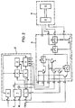
- FIG. 2 contains the known teletext decoder already described in FIG. 1, consisting of a video processor 1, a data processing circuit 2, a page memory 3, a character generator 4, a clock controller 5, a teletext remote control interface 6 and a voltage stabilizer 7.
- the teletext recording adapter is connected to this known teletext decoder in the manner shown in FIG.
- the inputs of this teletext recording adapter are labeled k, m, n, o, p, q, and r, and the outputs are labeled s and t, the output t also being used as an input in a specific operating mode, as will be explained later becomes.
- the inputs k and n of the teletext recording adapter serve as supply inputs.
- the voltages of 5 V and 12 V generated in the voltage stabilizer 7 of the teletext decoder are supplied to them.
- the teletext luminance signal generated in the character generator 4 of the teletext decoder and tapped at the output i of the teletext decoder is present at the input m of the teletext recording adapter.
- the input o of the teletext recording adapter is connected to the output h of the teletext decoder, so that the blanking or blanking signal output by the character generator 4 is supplied to the teletext recording adapter via its input o, which blank in the teletext recording adapter is used as a switching signal for the keying in of the decoded teletext signal in the CVBS signal present at input q of the teletext recording adapter is used.
- the teletext recording adapter has an input p at which the synchronous mixture generated in the clock controller 5, passed on to the video processor via line L and tapped at the output j of the teletext decoder is present.
- This sync mix is used in full-screen text recording, i. that is, if the entire picture is to be blanked and only text is to be recorded on the recorder.
- the teletext recording adapter still needs the switching voltage generated in the home video recorder, which is 0 V in the "recording" operating mode and 12 V in the “playback” operating mode, and is removed at pin 1 of the AV socket 12 of the AV coupling part K. can be and is commonly referred to as AV switching voltage.
- AV stands for audio-video, because the audio and video signal is coupled in and out via the AV socket.
- the teletext recording adapter has an output s for screen display and an output t for recording the signal on the connected home video recorder, output t being used during playback as an input for the signal coming from the home video recorder.
- the level of the switching signal which is fed to the teletext recording adapter via its connection o is at "LOW".
- switch S2 is closed and switch S1 is opened.
- These switches are used for fast signal switching (composite video teletext) within the television grid.
- the CVBS signal present at input q can thus be passed on to the home video recorder via the closed switches S2 and S3 (S3 is always closed in recording mode) via the output t of the teletext recording adapter.
- the switch S4 is open in the recording mode and closed in the playback mode.
- the level of the changeover signal present at connection o is "HIGH". This causes transistor T2 to conduct and transistor T3 to turn off. As a result, switch S1 is closed and switch S2 is opened.
- the decoded text signal present at input m can thus be passed on to the recording device via the closed switches S1 and S3 via the output t of the teletext recording adapter.
- the decoded teletext signal is therefore keyed into the CVBS signal present at the input q of the teletext recording adapter, so that the decoded teletext signal is recorded in synchronism with the CVBS signal on the home video recorder.
- the picture blanking or switching signal fed to the input o of the teletext recording adapter has the level "HIGH", so that the transistor T2 is always on.
- the synchronous mixture present at the input p of the teletext recording adapter can then be supplied to the switch S1 via the transistors T4, T2 and T3.
- FIG. 3 shows an example of how the AV coupling part K shown in FIG. 2, via which the output signals of the teletext recording adapter A are fed to the video recorder 15, in the video line 17 between the AV socket 13 of the television receiver 14 and the AV -Socket 16 of the video recorder 15 can be arranged.
- the AV connector of the AV coupling part K is designated, which is inserted into the AV socket 13 of the television receiver.
- the video recorder 15 is connected via the video line 17 to the AV socket 12 of the AV coupling part K.
- An advantageous development of the invention consists in connecting the teletext recording adapter and the AV coupling part to form a structural unit which, as an additional component, only needs to be connected to the teletext decoder of the television receiver.
- switches S1 and S2 are combined into a single switch.
Landscapes
- Engineering & Computer Science (AREA)
- Multimedia (AREA)
- Signal Processing (AREA)
- Television Signal Processing For Recording (AREA)
- Television Systems (AREA)
Claims (7)
Priority Applications (1)
| Application Number | Priority Date | Filing Date | Title |
|---|---|---|---|
| AT85100987T ATE41280T1 (de) | 1984-05-10 | 1985-01-31 | Videoheimanlage mit einem videotextdecoder. |
Applications Claiming Priority (2)
| Application Number | Priority Date | Filing Date | Title |
|---|---|---|---|
| DE3417276 | 1984-05-10 | ||
| DE3417276A DE3417276C2 (de) | 1984-05-10 | 1984-05-10 | Videoheimanlage mit einem Videotextdecoder |
Publications (2)
| Publication Number | Publication Date |
|---|---|
| EP0163807A1 EP0163807A1 (fr) | 1985-12-11 |
| EP0163807B1 true EP0163807B1 (fr) | 1989-03-08 |
Family
ID=6235436
Family Applications (1)
| Application Number | Title | Priority Date | Filing Date |
|---|---|---|---|
| EP85100987A Expired EP0163807B1 (fr) | 1984-05-10 | 1985-01-31 | Système de vidéo domestique avec décodeur de télétexte |
Country Status (3)
| Country | Link |
|---|---|
| EP (1) | EP0163807B1 (fr) |
| AT (1) | ATE41280T1 (fr) |
| DE (1) | DE3417276C2 (fr) |
Cited By (1)
| Publication number | Priority date | Publication date | Assignee | Title |
|---|---|---|---|---|
| DE3928175A1 (de) * | 1989-01-21 | 1990-07-26 | Nokia Unterhaltungselektronik | Videoempfangseinrichtung |
Families Citing this family (3)
| Publication number | Priority date | Publication date | Assignee | Title |
|---|---|---|---|---|
| DE3733563A1 (de) * | 1987-10-03 | 1989-04-20 | Grundig Emv | Einrichtung zur wiedergabe eines auf einem magnetband eines videorecorders aufgezeichneten videosignals |
| DE3920234A1 (de) * | 1989-06-21 | 1991-01-03 | Thomson Brandt Gmbh | Videorecorder mit erzeugung eines textsignals |
| FR2670982A1 (fr) * | 1990-12-21 | 1992-06-26 | Thomson Consumer Electronics | Procede de synchronisation de fonctions de commande avec des signaux video dans un recepteur de television et dispositif de mise en óoeuvre. |
Family Cites Families (2)
| Publication number | Priority date | Publication date | Assignee | Title |
|---|---|---|---|---|
| DE3315687C1 (de) * | 1983-04-29 | 1984-11-22 | Telefunken Fernseh Und Rundfunk Gmbh, 3000 Hannover | Schaltung zur Aufzeichnung eines Fernsehbildsignals und eines Videotextsignals mit einem Videorecorder |
| DE3315740C2 (de) * | 1983-04-30 | 1985-02-21 | Telefunken Fernseh Und Rundfunk Gmbh, 3000 Hannover | Videorecorder mit Aufzeichnung eines Videotext-Signals |
-
1984
- 1984-05-10 DE DE3417276A patent/DE3417276C2/de not_active Expired
-
1985
- 1985-01-31 EP EP85100987A patent/EP0163807B1/fr not_active Expired
- 1985-01-31 AT AT85100987T patent/ATE41280T1/de active
Cited By (1)
| Publication number | Priority date | Publication date | Assignee | Title |
|---|---|---|---|---|
| DE3928175A1 (de) * | 1989-01-21 | 1990-07-26 | Nokia Unterhaltungselektronik | Videoempfangseinrichtung |
Also Published As
| Publication number | Publication date |
|---|---|
| EP0163807A1 (fr) | 1985-12-11 |
| DE3417276C2 (de) | 1987-02-19 |
| DE3417276A1 (de) | 1985-11-14 |
| ATE41280T1 (de) | 1989-03-15 |
Similar Documents
| Publication | Publication Date | Title |
|---|---|---|
| US4568981A (en) | Font recall system and method of operation | |
| DE69606185T2 (de) | Digitale aufnahme- und wiedergabevorrichtung | |
| DE3923907C2 (fr) | ||
| DE69608784T2 (de) | Verfahren und vorrichtung zur verhütung von explosion und brand für elektrische transformatoren | |
| DE69516780T2 (de) | Schnittstelle für eine Programmführung | |
| DE69805545T2 (de) | Gerät zur erzeugung eines digitalen videobildes | |
| DE69129730T2 (de) | Vorrichtung zum Verarbeiten von Bilddaten | |
| EP0163807B1 (fr) | Système de vidéo domestique avec décodeur de télétexte | |
| EP0387517B1 (fr) | Dispositif pour le traitement de signaux de réception de télévision dans le but de reconnaître et de choisir le format d'image | |
| EP0421017B1 (fr) | Dispositif d'insertion d'image dans l'image pour un récepteur de télévision avec un seul tuner | |
| US5786863A (en) | High resolution recording and transmission technique for computer video and other non-television formatted video signals | |
| EP0695491B1 (fr) | Procede d'enregistrement ou de lecture compatibles de signaux de television | |
| EP0746165B1 (fr) | Dispositif de réception de signaux de télévision analogiques et/ou numériques avec un circuit de réception accordable | |
| DE3823284A1 (de) | Geraet zum verarbeiten von videosignalen | |
| DE3642186A1 (de) | Videorecorder mit einem zweiten videosignalweg | |
| EP0129648B1 (fr) | Récepteur de télévision avec insertion de texte | |
| DE69822883T2 (de) | Gerät zur erzeugung der digitalen daten für bilder in einer animations-/informationsfolge für eine elektrische vorrichtung | |
| DE19621778A1 (de) | Bildverarbeitungsvorrichtung und Verfahren zur Auswahl einer zugehörigen Eingangs-/Ausgangsquelle | |
| DE19815808B4 (de) | Videorecorder | |
| EP0310880A1 (fr) | Dispositif de reproduction d'un signal vidéo enregistré sur une bande magnétique d'un magnétoscope | |
| EP0695086B1 (fr) | Procédé de transmission d'un signal de télévision, d'un signal d'accompagnement et d'un signal de commande pour un affichage en image grande ou réduite | |
| EP0367929A2 (fr) | Dispositif de réduction du papillotement dans les récepteurs de télévision | |
| EP0429789B1 (fr) | Dispositif pour le traitement de deux signaux vidéo | |
| DE3421780C2 (de) | Verfahren und Monitor zur Wiedergabe eines Ausschnittes eines Videobildes | |
| DE4103539A1 (de) | Fernsehmonitor mit einer bild-im-bild-verarbeitung |
Legal Events
| Date | Code | Title | Description |
|---|---|---|---|
| PUAI | Public reference made under article 153(3) epc to a published international application that has entered the european phase |
Free format text: ORIGINAL CODE: 0009012 |
|
| AK | Designated contracting states |
Designated state(s): AT FR GB IT |
|
| 17P | Request for examination filed |
Effective date: 19860524 |
|
| 17Q | First examination report despatched |
Effective date: 19880128 |
|
| GRAA | (expected) grant |
Free format text: ORIGINAL CODE: 0009210 |
|
| AK | Designated contracting states |
Kind code of ref document: B1 Designated state(s): AT FR GB IT |
|
| REF | Corresponds to: |
Ref document number: 41280 Country of ref document: AT Date of ref document: 19890315 Kind code of ref document: T |
|
| GBT | Gb: translation of ep patent filed (gb section 77(6)(a)/1977) | ||
| ET | Fr: translation filed | ||
| ITF | It: translation for a ep patent filed | ||
| PLBE | No opposition filed within time limit |
Free format text: ORIGINAL CODE: 0009261 |
|
| STAA | Information on the status of an ep patent application or granted ep patent |
Free format text: STATUS: NO OPPOSITION FILED WITHIN TIME LIMIT |
|
| 26N | No opposition filed | ||
| ITTA | It: last paid annual fee | ||
| PGFP | Annual fee paid to national office [announced via postgrant information from national office to epo] |
Ref country code: AT Payment date: 19921230 Year of fee payment: 9 |
|
| PG25 | Lapsed in a contracting state [announced via postgrant information from national office to epo] |
Ref country code: AT Effective date: 19940131 |
|
| REG | Reference to a national code |
Ref country code: GB Ref legal event code: 746 Effective date: 19940208 |
|
| ITPR | It: changes in ownership of a european patent |
Owner name: OFFERTA DI LICENZA AL PUBBLICO |
|
| REG | Reference to a national code |
Ref country code: FR Ref legal event code: DL |
|
| PGFP | Annual fee paid to national office [announced via postgrant information from national office to epo] |
Ref country code: GB Payment date: 19950123 Year of fee payment: 11 |
|
| PGFP | Annual fee paid to national office [announced via postgrant information from national office to epo] |
Ref country code: FR Payment date: 19951227 Year of fee payment: 12 |
|
| PG25 | Lapsed in a contracting state [announced via postgrant information from national office to epo] |
Ref country code: GB Effective date: 19960131 |
|
| REG | Reference to a national code |
Ref country code: FR Ref legal event code: CD |
|
| GBPC | Gb: european patent ceased through non-payment of renewal fee |
Effective date: 19960131 |
|
| PG25 | Lapsed in a contracting state [announced via postgrant information from national office to epo] |
Ref country code: FR Effective date: 19960930 |
|
| REG | Reference to a national code |
Ref country code: FR Ref legal event code: ST |