EP0163821A1 - Appareil pour l'aération de bassins d'eau usée et d'étangs - Google Patents
Appareil pour l'aération de bassins d'eau usée et d'étangs Download PDFInfo
- Publication number
- EP0163821A1 EP0163821A1 EP85102903A EP85102903A EP0163821A1 EP 0163821 A1 EP0163821 A1 EP 0163821A1 EP 85102903 A EP85102903 A EP 85102903A EP 85102903 A EP85102903 A EP 85102903A EP 0163821 A1 EP0163821 A1 EP 0163821A1
- Authority
- EP
- European Patent Office
- Prior art keywords
- compressor
- pipe
- ventilation device
- water
- distributor pipe
- Prior art date
- Legal status (The legal status is an assumption and is not a legal conclusion. Google has not performed a legal analysis and makes no representation as to the accuracy of the status listed.)
- Withdrawn
Links
- 238000005273 aeration Methods 0.000 title claims description 7
- 239000002351 wastewater Substances 0.000 title description 4
- XLYOFNOQVPJJNP-UHFFFAOYSA-N water Substances O XLYOFNOQVPJJNP-UHFFFAOYSA-N 0.000 claims abstract description 20
- 239000007788 liquid Substances 0.000 claims abstract description 3
- 238000009423 ventilation Methods 0.000 claims description 10
- 238000003958 fumigation Methods 0.000 claims description 7
- 239000010865 sewage Substances 0.000 claims description 5
- 230000005484 gravity Effects 0.000 claims description 2
- 238000004065 wastewater treatment Methods 0.000 claims description 2
- 230000001174 ascending effect Effects 0.000 claims 1
- 239000000725 suspension Substances 0.000 claims 1
- 238000005276 aerator Methods 0.000 description 5
- QVGXLLKOCUKJST-UHFFFAOYSA-N atomic oxygen Chemical compound [O] QVGXLLKOCUKJST-UHFFFAOYSA-N 0.000 description 3
- 238000012423 maintenance Methods 0.000 description 3
- 239000001301 oxygen Substances 0.000 description 3
- 229910052760 oxygen Inorganic materials 0.000 description 3
- 230000000630 rising effect Effects 0.000 description 3
- 238000005352 clarification Methods 0.000 description 2
- 239000010802 sludge Substances 0.000 description 2
- 239000000470 constituent Substances 0.000 description 1
- 238000006073 displacement reaction Methods 0.000 description 1
- 238000003780 insertion Methods 0.000 description 1
- 230000037431 insertion Effects 0.000 description 1
- 238000009434 installation Methods 0.000 description 1
Images

Classifications
-
- C—CHEMISTRY; METALLURGY
- C02—TREATMENT OF WATER, WASTE WATER, SEWAGE, OR SLUDGE
- C02F—TREATMENT OF WATER, WASTE WATER, SEWAGE, OR SLUDGE
- C02F3/00—Biological treatment of water, waste water, or sewage
- C02F3/02—Aerobic processes
- C02F3/12—Activated sludge processes
- C02F3/20—Activated sludge processes using diffusers
-
- B—PERFORMING OPERATIONS; TRANSPORTING
- B01—PHYSICAL OR CHEMICAL PROCESSES OR APPARATUS IN GENERAL
- B01F—MIXING, e.g. DISSOLVING, EMULSIFYING OR DISPERSING
- B01F23/00—Mixing according to the phases to be mixed, e.g. dispersing or emulsifying
- B01F23/20—Mixing gases with liquids
- B01F23/23—Mixing gases with liquids by introducing gases into liquid media, e.g. for producing aerated liquids
- B01F23/231—Mixing gases with liquids by introducing gases into liquid media, e.g. for producing aerated liquids by bubbling
- B01F23/23105—Arrangement or manipulation of the gas bubbling devices
- B01F23/2311—Mounting the bubbling devices or the diffusers
-
- B—PERFORMING OPERATIONS; TRANSPORTING
- B01—PHYSICAL OR CHEMICAL PROCESSES OR APPARATUS IN GENERAL
- B01F—MIXING, e.g. DISSOLVING, EMULSIFYING OR DISPERSING
- B01F23/00—Mixing according to the phases to be mixed, e.g. dispersing or emulsifying
- B01F23/20—Mixing gases with liquids
- B01F23/23—Mixing gases with liquids by introducing gases into liquid media, e.g. for producing aerated liquids
- B01F23/231—Mixing gases with liquids by introducing gases into liquid media, e.g. for producing aerated liquids by bubbling
- B01F23/23105—Arrangement or manipulation of the gas bubbling devices
- B01F23/2311—Mounting the bubbling devices or the diffusers
- B01F23/23112—Mounting the bubbling devices or the diffusers comprising the use of flow guiding elements adjacent or above the gas stream
- B01F23/231121—Mounting the bubbling devices or the diffusers comprising the use of flow guiding elements adjacent or above the gas stream the flow guiding elements being baffles, tubes or walls
-
- B—PERFORMING OPERATIONS; TRANSPORTING
- B01—PHYSICAL OR CHEMICAL PROCESSES OR APPARATUS IN GENERAL
- B01F—MIXING, e.g. DISSOLVING, EMULSIFYING OR DISPERSING
- B01F23/00—Mixing according to the phases to be mixed, e.g. dispersing or emulsifying
- B01F23/20—Mixing gases with liquids
- B01F23/23—Mixing gases with liquids by introducing gases into liquid media, e.g. for producing aerated liquids
- B01F23/231—Mixing gases with liquids by introducing gases into liquid media, e.g. for producing aerated liquids by bubbling
- B01F23/23105—Arrangement or manipulation of the gas bubbling devices
- B01F23/2311—Mounting the bubbling devices or the diffusers
- B01F23/23114—Mounting the bubbling devices or the diffusers characterised by the way in which the different elements of the bubbling installation are mounted
- B01F23/231141—Mounting auxiliary devices, e.g. pumps or compressors in a particular place on the bubbling installation, e.g. under water
-
- B—PERFORMING OPERATIONS; TRANSPORTING
- B01—PHYSICAL OR CHEMICAL PROCESSES OR APPARATUS IN GENERAL
- B01F—MIXING, e.g. DISSOLVING, EMULSIFYING OR DISPERSING
- B01F23/00—Mixing according to the phases to be mixed, e.g. dispersing or emulsifying
- B01F23/20—Mixing gases with liquids
- B01F23/23—Mixing gases with liquids by introducing gases into liquid media, e.g. for producing aerated liquids
- B01F23/231—Mixing gases with liquids by introducing gases into liquid media, e.g. for producing aerated liquids by bubbling
- B01F23/23105—Arrangement or manipulation of the gas bubbling devices
- B01F23/2311—Mounting the bubbling devices or the diffusers
- B01F23/23115—Mounting the bubbling devices or the diffusers characterised by the way in which the bubbling devices are mounted within the receptacle
- B01F23/231152—Mounting the bubbling devices or the diffusers characterised by the way in which the bubbling devices are mounted within the receptacle the bubbling devices being supported, e.g. on cables or laying on the bottom
-
- B—PERFORMING OPERATIONS; TRANSPORTING
- B01—PHYSICAL OR CHEMICAL PROCESSES OR APPARATUS IN GENERAL
- B01F—MIXING, e.g. DISSOLVING, EMULSIFYING OR DISPERSING
- B01F23/00—Mixing according to the phases to be mixed, e.g. dispersing or emulsifying
- B01F23/20—Mixing gases with liquids
- B01F23/23—Mixing gases with liquids by introducing gases into liquid media, e.g. for producing aerated liquids
- B01F23/231—Mixing gases with liquids by introducing gases into liquid media, e.g. for producing aerated liquids by bubbling
- B01F23/23105—Arrangement or manipulation of the gas bubbling devices
- B01F23/2311—Mounting the bubbling devices or the diffusers
- B01F23/23115—Mounting the bubbling devices or the diffusers characterised by the way in which the bubbling devices are mounted within the receptacle
- B01F23/231153—Mounting the bubbling devices or the diffusers characterised by the way in which the bubbling devices are mounted within the receptacle the bubbling devices being suspended on a supporting construction, i.e. not on a floating construction
-
- B—PERFORMING OPERATIONS; TRANSPORTING
- B01—PHYSICAL OR CHEMICAL PROCESSES OR APPARATUS IN GENERAL
- B01F—MIXING, e.g. DISSOLVING, EMULSIFYING OR DISPERSING
- B01F23/00—Mixing according to the phases to be mixed, e.g. dispersing or emulsifying
- B01F23/20—Mixing gases with liquids
- B01F23/23—Mixing gases with liquids by introducing gases into liquid media, e.g. for producing aerated liquids
- B01F23/231—Mixing gases with liquids by introducing gases into liquid media, e.g. for producing aerated liquids by bubbling
- B01F23/23105—Arrangement or manipulation of the gas bubbling devices
- B01F23/2312—Diffusers
- B01F23/23126—Diffusers characterised by the shape of the diffuser element
- B01F23/231265—Diffusers characterised by the shape of the diffuser element being tubes, tubular elements, cylindrical elements or set of tubes
-
- C—CHEMISTRY; METALLURGY
- C02—TREATMENT OF WATER, WASTE WATER, SEWAGE, OR SLUDGE
- C02F—TREATMENT OF WATER, WASTE WATER, SEWAGE, OR SLUDGE
- C02F7/00—Aeration of stretches of water
-
- B—PERFORMING OPERATIONS; TRANSPORTING
- B01—PHYSICAL OR CHEMICAL PROCESSES OR APPARATUS IN GENERAL
- B01F—MIXING, e.g. DISSOLVING, EMULSIFYING OR DISPERSING
- B01F33/00—Other mixers; Mixing plants; Combinations of mixers
- B01F33/50—Movable or transportable mixing devices or plants
- B01F33/503—Floating mixing devices
-
- Y—GENERAL TAGGING OF NEW TECHNOLOGICAL DEVELOPMENTS; GENERAL TAGGING OF CROSS-SECTIONAL TECHNOLOGIES SPANNING OVER SEVERAL SECTIONS OF THE IPC; TECHNICAL SUBJECTS COVERED BY FORMER USPC CROSS-REFERENCE ART COLLECTIONS [XRACs] AND DIGESTS
- Y02—TECHNOLOGIES OR APPLICATIONS FOR MITIGATION OR ADAPTATION AGAINST CLIMATE CHANGE
- Y02W—CLIMATE CHANGE MITIGATION TECHNOLOGIES RELATED TO WASTEWATER TREATMENT OR WASTE MANAGEMENT
- Y02W10/00—Technologies for wastewater treatment
- Y02W10/10—Biological treatment of water, waste water, or sewage
Definitions
- the invention relates to a device for ventilating wastewater treatment tanks, in particular sewage ponds, consisting of a unit which can be inserted or removed from the tank as a whole, which produces a compressed air-producing, underwater arranged compressor with an air intake pipe raised above the liquid level and one from the compressor Compressed air manifold to which one or more porous fumigation bodies are connected.
- the porous fumigation bodies are supplied with compressed air by a compressor.
- Clarification ponds sometimes have large dimensions.
- the punctiform or linear introduction of atmospheric oxygen is carried out from individual units, which are often far from the edge of the pond.
- the units must be lifted out of the pond for repair and maintenance work. Since they are connected to a common compressor, long supply lines for the compressed air are necessary. During maintenance work, the units must remain connected to the supply lines until the units are above water, otherwise they would run full of water.
- DE-GM 83 17 605 hoses from the distribution line permanently installed at the edge of the pond to lead to the aeration units, the aeration units being provided with chassis with which they could be moved in shoes laid on the pond slope. With such an arrangement there is the disadvantage of high expenditure.
- the sludge in the sewage pond can rise so high that the rails are covered.
- the ventilation unit can then no longer be pulled out at all.
- Another previously known ventilation device (DE-GM 82 11 192) consists of a frame supported by floats and spanning the entire pool, which can be moved lengthways through the ventilation pool by means of a rope. Compressed air generators are attached to the frame under water, the air intake pipes of which are drawn up over the surface of the water. The tubes of the frame are used for air conduction to the fumigation bodies attached to a distribution tube at the bottom.
- a device cannot be used in sewage ponds with large dimensions, because there the frame would become unacceptably large and the effort for the displacement device would be too great.
- the invention has the purpose of providing a device suitable for pond aeration.
- the stated object is achieved in that the compressor is placed directly on the distributor pipe and connected to it to form a self-supporting structural unit.
- the compact aerator unit can be offered in two versions: as a standing device and as a floating device.
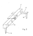
- the standing device one will advantageously attach a traverse to the distributor tube receiving the gassing body at one end and provide the two ends of the crossbar and the opposite end of the distributor tube with support feet. This results in a stable three-point support.
- the floats are preferably attached to the air intake tube.
- the floats can be wedge-shaped.
- the perforated hoses used in the fumigation bodies are non-clogging and essentially watertight. Leakage of another kind could cause water to get into the compressor and the motor if the compressor fails, which must be prevented under all circumstances. It is therefore proposed according to the innovation to first guide the pressure pipe from the compressor in the loop over water and only then to connect it to the fumigation bodies. The water then rises in the downward direction directed part of the loop up to the water level, but cannot get into the compressor.
- the loop lying above water is arranged exactly above the center of gravity of the device, so that the device can be suspended from this loop and moved.
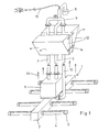
- hose 1 consists of a central distributor pipe 2 and a plurality of aerator pipes 3 attached to the side with a perforated hose cover 4.
- a housing 5 is connected, which contains the compressor and the drive motor.
- the suction line 6 and the pressure line 7 are guided upwards from this housing 5.
- the suction line 6 ends above the water level 11 in a suction filter 8, while the pressure line 7 is guided downwards again to the distributor pipe 2 in a loop 9 and a descending branch 10.
- the connections on the housing 5, on the distributor pipe 2 and on the loop 9 are designed as flange connections, so that the device can be adapted to different water depths by inserting pipe sections of different lengths.
- Floats 12 are attached to the two branches 7, 10 of the pressure line in the upper region. They have a wedge shape that tapers downwards, so that the bubble stream 13 rising from the aerator tubes 3 is deflected laterally. The floats 12 are clamped in height-adjustable manner on the tubes by means of tensioning straps 14, so that the distance between the aerator tubes 3 and the pool floor can be adjusted as desired.
- the power cable 16 for the drive motor of the compressor is inserted into the above-water end of the intake pipe 6 and runs inside the pipe into the underwater housing 5. This saves a watertight insertion.
- the distributor pipe which belongs to a displaceable structural unit, has at one end a crossmember 17 which is provided with two support feet 18. The opposite end of the manifold carries the third support leg.
Landscapes
- Chemical & Material Sciences (AREA)
- Chemical Kinetics & Catalysis (AREA)
- Life Sciences & Earth Sciences (AREA)
- Hydrology & Water Resources (AREA)
- Engineering & Computer Science (AREA)
- Environmental & Geological Engineering (AREA)
- Water Supply & Treatment (AREA)
- Organic Chemistry (AREA)
- Biodiversity & Conservation Biology (AREA)
- Microbiology (AREA)
- Aeration Devices For Treatment Of Activated Polluted Sludge (AREA)
Applications Claiming Priority (2)
| Application Number | Priority Date | Filing Date | Title |
|---|---|---|---|
| DE19848413384U DE8413384U1 (de) | 1984-05-02 | 1984-05-02 | Belueftungseinrichtung |
| DE8413384U | 1984-05-02 |
Publications (1)
| Publication Number | Publication Date |
|---|---|
| EP0163821A1 true EP0163821A1 (fr) | 1985-12-11 |
Family
ID=6766472
Family Applications (1)
| Application Number | Title | Priority Date | Filing Date |
|---|---|---|---|
| EP85102903A Withdrawn EP0163821A1 (fr) | 1984-05-02 | 1985-03-13 | Appareil pour l'aération de bassins d'eau usée et d'étangs |
Country Status (2)
| Country | Link |
|---|---|
| EP (1) | EP0163821A1 (fr) |
| DE (1) | DE8413384U1 (fr) |
Cited By (13)
| Publication number | Priority date | Publication date | Assignee | Title |
|---|---|---|---|---|
| EP0276759A1 (fr) * | 1987-01-30 | 1988-08-03 | Heinz Dipl.-Ing. Gaspard | Bassin d'aération pour cuves d'installation de clarification ou de stations d'épuration des eaux |
| EP0345207A1 (fr) * | 1988-06-03 | 1989-12-06 | Ott, Rita | Dispositif d'aération |
| GB2234235A (en) * | 1989-04-26 | 1991-01-30 | Elisabeth Mary Campbell | Aerating liquids |
| EP0547254A1 (fr) * | 1991-12-14 | 1993-06-23 | Peter Wilms | Procédé pour créer un courant d'air ou d'oxygène dans les installations de clarification biologique |
| AT402201B (de) * | 1994-06-17 | 1997-03-25 | Udo Meyer Aquaconsult Gmbh | Einrichtung zum feinblasigen eintrag von gasen in flüssigkeiten |
| US5750881A (en) * | 1995-07-13 | 1998-05-12 | Chiron Diagnostics Corporation | Method and apparatus for aspirating and dispensing sample fluids |
| US6158269A (en) * | 1995-07-13 | 2000-12-12 | Bayer Corporation | Method and apparatus for aspirating and dispensing sample fluids |
| DE102007033483A1 (de) * | 2007-07-18 | 2009-01-22 | Bioworks Verfahrenstechnik Gmbh | Tauchbelüfter |
| WO2009053975A1 (fr) * | 2007-10-22 | 2009-04-30 | M.P.L. Green Energy Ltd. | Dispositif d'aération destiné à introduire des bulles de gaz dans un milieu liquide |
| US8241497B2 (en) | 2007-07-18 | 2012-08-14 | Bioworks Verfahrenstechnik Gmbh | Method for stirring and/or aerating fluids, particularly sewage, particularly using a floodable aerator |
| WO2014005199A1 (fr) | 2012-07-05 | 2014-01-09 | Atlas Copco Airpower | Dispositif d'aération, son utilisation et installation de purification d'eau comprenant un tel dispositif d'aération |
| EP2937317A1 (fr) * | 2014-04-25 | 2015-10-28 | e-proxi ag | Installation d'aération des eaux usées et procédé d'aération des eaux usées |
| CN112774300A (zh) * | 2020-12-17 | 2021-05-11 | 深圳市星源空间环境技术有限公司 | 一种污水处理设备 |
Citations (4)
| Publication number | Priority date | Publication date | Assignee | Title |
|---|---|---|---|---|
| CH493263A (de) * | 2012-02-09 | 1970-07-15 | Stenberg Flygt Ab | Verfahren zur Belüftung einer Flüssigkeit sowie Vorrichtung zur Ausübung des Verfahrens |
| DE2649500A1 (de) * | 1975-10-31 | 1977-05-12 | Alec Hibburd Laurie | Vorrichtung zum anreichern einer fluessigkeit mit gas, insbesondere luft |
| US4229302A (en) * | 1978-10-20 | 1980-10-21 | Clevepak Corporation | Waste treatment apparatus with floating platform |
| EP0089465A1 (fr) * | 1982-03-22 | 1983-09-28 | BLUM, Albert | Aérateur immergé |
-
1984
- 1984-05-02 DE DE19848413384U patent/DE8413384U1/de not_active Expired
-
1985
- 1985-03-13 EP EP85102903A patent/EP0163821A1/fr not_active Withdrawn
Patent Citations (4)
| Publication number | Priority date | Publication date | Assignee | Title |
|---|---|---|---|---|
| DE2649500A1 (de) * | 1975-10-31 | 1977-05-12 | Alec Hibburd Laurie | Vorrichtung zum anreichern einer fluessigkeit mit gas, insbesondere luft |
| US4229302A (en) * | 1978-10-20 | 1980-10-21 | Clevepak Corporation | Waste treatment apparatus with floating platform |
| EP0089465A1 (fr) * | 1982-03-22 | 1983-09-28 | BLUM, Albert | Aérateur immergé |
| CH493263A (de) * | 2012-02-09 | 1970-07-15 | Stenberg Flygt Ab | Verfahren zur Belüftung einer Flüssigkeit sowie Vorrichtung zur Ausübung des Verfahrens |
Cited By (21)
| Publication number | Priority date | Publication date | Assignee | Title |
|---|---|---|---|---|
| EP0276759A1 (fr) * | 1987-01-30 | 1988-08-03 | Heinz Dipl.-Ing. Gaspard | Bassin d'aération pour cuves d'installation de clarification ou de stations d'épuration des eaux |
| EP0345207A1 (fr) * | 1988-06-03 | 1989-12-06 | Ott, Rita | Dispositif d'aération |
| GB2234235A (en) * | 1989-04-26 | 1991-01-30 | Elisabeth Mary Campbell | Aerating liquids |
| GB2234235B (en) * | 1989-04-26 | 1992-10-14 | Campbell Elisabeth Mary | Improved flotation for aerators |
| EP0547254A1 (fr) * | 1991-12-14 | 1993-06-23 | Peter Wilms | Procédé pour créer un courant d'air ou d'oxygène dans les installations de clarification biologique |
| AT402201B (de) * | 1994-06-17 | 1997-03-25 | Udo Meyer Aquaconsult Gmbh | Einrichtung zum feinblasigen eintrag von gasen in flüssigkeiten |
| US5750881A (en) * | 1995-07-13 | 1998-05-12 | Chiron Diagnostics Corporation | Method and apparatus for aspirating and dispensing sample fluids |
| US6158269A (en) * | 1995-07-13 | 2000-12-12 | Bayer Corporation | Method and apparatus for aspirating and dispensing sample fluids |
| US8241497B2 (en) | 2007-07-18 | 2012-08-14 | Bioworks Verfahrenstechnik Gmbh | Method for stirring and/or aerating fluids, particularly sewage, particularly using a floodable aerator |
| DE102007033483A1 (de) * | 2007-07-18 | 2009-01-22 | Bioworks Verfahrenstechnik Gmbh | Tauchbelüfter |
| WO2009053975A1 (fr) * | 2007-10-22 | 2009-04-30 | M.P.L. Green Energy Ltd. | Dispositif d'aération destiné à introduire des bulles de gaz dans un milieu liquide |
| US8500107B2 (en) | 2007-10-22 | 2013-08-06 | Mapal Green Energy Ltd. | Aeration device for the introduction of gas bubbles into a liquid medium |
| RU2491116C2 (ru) * | 2007-10-22 | 2013-08-27 | МЭЙПАЛ Грин Энерджи Лтд. | Аэрационное устройство для введения пузырьков газа в жидкую среду |
| WO2014005199A1 (fr) | 2012-07-05 | 2014-01-09 | Atlas Copco Airpower | Dispositif d'aération, son utilisation et installation de purification d'eau comprenant un tel dispositif d'aération |
| BE1020820A3 (nl) * | 2012-07-05 | 2014-05-06 | Atlas Copco Airpower Nv | Beluchtingstoestel, een gebruik ervan, en waterzuiveringsinstallatie met een dergelijk beluchtingstoestel. |
| JP2015527184A (ja) * | 2012-07-05 | 2015-09-17 | アトラス コプコ エアーパワー, ナームローゼ フェンノートシャップATLAS COPCO AIRPOWER, naamloze vennootschap | 曝気装置、その使用方法、及び、この曝気装置を備えた浄水設備 |
| RU2609494C2 (ru) * | 2012-07-05 | 2017-02-02 | Атлас Копко Эрпауэр, Намлозе Веннотсхап | Устройство для аэрации, его применение и водоочистительная установка с таким устройством для аэрации |
| US9844760B2 (en) | 2012-07-05 | 2017-12-19 | Atlas Copco Airpower, Naamloze Vennootschap | Aeration device, a use thereof, and water purification installation with such an aeration device |
| EP2937317A1 (fr) * | 2014-04-25 | 2015-10-28 | e-proxi ag | Installation d'aération des eaux usées et procédé d'aération des eaux usées |
| WO2015162240A1 (fr) * | 2014-04-25 | 2015-10-29 | E-Proxi Ag | Installation de ventilation des eaux usées et procédé de ventilation des eaux usées |
| CN112774300A (zh) * | 2020-12-17 | 2021-05-11 | 深圳市星源空间环境技术有限公司 | 一种污水处理设备 |
Also Published As
| Publication number | Publication date |
|---|---|
| DE8413384U1 (de) | 1984-08-16 |
Similar Documents
| Publication | Publication Date | Title |
|---|---|---|
| EP0418571B1 (fr) | Dispositif pour l'épuration et l'aération des eaux ouvertes | |
| DE4001201C1 (fr) | ||
| DE8413384U1 (de) | Belueftungseinrichtung | |
| DE2216917C3 (de) | Vorrichtung zum Lösen von Sauerstoff in Wasser | |
| DE69001250T2 (de) | Vorrichtung für die neutralisation von organischen stoffen und für die beseitigung von phosphor enthaltenden verbindungen in wasserbecken. | |
| EP1072560A1 (fr) | Dispositif pour disperser des bulles d'air fines dans de l'eau | |
| DE4405961C2 (de) | Vorrichtung zum Begasen einer Flüssigkeit | |
| DE2857345C2 (de) | Vorrichtung zum biologischen Reinigen von Abwasser | |
| DE2909724C2 (de) | Anlage für die biologische Abwasserreinigung | |
| DE3017289C2 (de) | Vorrichtung zum biologischen Reinigen von Abwasser | |
| DE3610744A1 (de) | Vorrichtung zur direkten belueftung und umwaelzung von insbesondere abwaessern | |
| DE2231061A1 (de) | Vorrichtung zum einbringen von gas in fluessigkeit | |
| DE3103306A1 (de) | "belueftungsvorrichtung fuer in oberflaechenwaesser zurueckzuleitende abwaesser, insbesondere fuer die anreicherung von gebrauchswaessern mit sauerstoff" | |
| EP0806400A1 (fr) | Aérateur courbé | |
| DE102009017067A1 (de) | Anlage zur biologischen Abwasserbehandlung | |
| DE3332074A1 (de) | Schwimmbeluefter fuer abwasserteiche | |
| DE10004077C1 (de) | Vorrichtung zum Belüften von natürlichen und künstlichen Gewässern, Behältern, Tanks und Becken | |
| WO2001025159A1 (fr) | Dispositif pour aerer des eaux naturelles et artificielles stagnantes ou non, des cuves, des reservoirs et des bassins | |
| DE4033167A1 (de) | Verfahren und vorrichtung zur fuehrung und positionierung von belueftungsaggregaten beim absenken in ein becken | |
| DE2800035A1 (de) | Verfahren und vorrichtung zur abwasserreinigung | |
| EP1293483A1 (fr) | Installation d'épuration des eaux usées équipée d'un dispositif d'aération | |
| DE3724692A1 (de) | Verfahren zum einbringen von sauerstoff in wasser und vorrichtung zur durchfuehrung des verfahrens | |
| DE29502701U1 (de) | Belüftungsvorrichtung für Abwässer | |
| DE2502661C3 (de) | Aggregat zum Einbau in Becken für die Belüftung und Behandlung von Abwasser | |
| DD233992A1 (de) | Einrichtung zur erhoehung der sauerstoffausnutzung in belebtschlammanlagen |
Legal Events
| Date | Code | Title | Description |
|---|---|---|---|
| PUAI | Public reference made under article 153(3) epc to a published international application that has entered the european phase |
Free format text: ORIGINAL CODE: 0009012 |
|
| AK | Designated contracting states |
Designated state(s): AT BE DE FR IT LU |
|
| STAA | Information on the status of an ep patent application or granted ep patent |
Free format text: STATUS: THE APPLICATION IS DEEMED TO BE WITHDRAWN |
|
| 18D | Application deemed to be withdrawn |
Effective date: 19860712 |
|
| RIN1 | Information on inventor provided before grant (corrected) |
Inventor name: MUSKAT, JOSEF, DR. RER. NAT. Inventor name: SCHMELZ, WOLFGANG |