EP0163832A1 - Geschichtete Sicherungsmutter - Google Patents
Geschichtete Sicherungsmutter Download PDFInfo
- Publication number
- EP0163832A1 EP0163832A1 EP85103469A EP85103469A EP0163832A1 EP 0163832 A1 EP0163832 A1 EP 0163832A1 EP 85103469 A EP85103469 A EP 85103469A EP 85103469 A EP85103469 A EP 85103469A EP 0163832 A1 EP0163832 A1 EP 0163832A1
- Authority
- EP
- European Patent Office
- Prior art keywords
- nut
- segments
- loading
- load
- bolt
- Prior art date
- Legal status (The legal status is an assumption and is not a legal conclusion. Google has not performed a legal analysis and makes no representation as to the accuracy of the status listed.)
- Granted
Links
- 239000000463 material Substances 0.000 claims abstract description 9
- 238000009987 spinning Methods 0.000 claims abstract description 4
- 230000007246 mechanism Effects 0.000 description 8
- 230000036316 preload Effects 0.000 description 7
- 230000009471 action Effects 0.000 description 6
- 230000000694 effects Effects 0.000 description 6
- 229910000639 Spring steel Inorganic materials 0.000 description 5
- 239000007787 solid Substances 0.000 description 5
- 241000406668 Loxodonta cyclotis Species 0.000 description 3
- 238000007906 compression Methods 0.000 description 3
- 230000008901 benefit Effects 0.000 description 2
- 230000000903 blocking effect Effects 0.000 description 2
- 230000008859 change Effects 0.000 description 2
- 230000006835 compression Effects 0.000 description 2
- 230000006872 improvement Effects 0.000 description 2
- 229910000831 Steel Inorganic materials 0.000 description 1
- 238000005452 bending Methods 0.000 description 1
- 238000010276 construction Methods 0.000 description 1
- 238000003780 insertion Methods 0.000 description 1
- 230000037431 insertion Effects 0.000 description 1
- 238000003475 lamination Methods 0.000 description 1
- 230000000717 retained effect Effects 0.000 description 1
- 230000035939 shock Effects 0.000 description 1
- 239000010959 steel Substances 0.000 description 1
Images


Classifications
-
- F—MECHANICAL ENGINEERING; LIGHTING; HEATING; WEAPONS; BLASTING
- F16—ENGINEERING ELEMENTS AND UNITS; GENERAL MEASURES FOR PRODUCING AND MAINTAINING EFFECTIVE FUNCTIONING OF MACHINES OR INSTALLATIONS; THERMAL INSULATION IN GENERAL
- F16B—DEVICES FOR FASTENING OR SECURING CONSTRUCTIONAL ELEMENTS OR MACHINE PARTS TOGETHER, e.g. NAILS, BOLTS, CIRCLIPS, CLAMPS, CLIPS OR WEDGES; JOINTS OR JOINTING
- F16B39/00—Locking of screws, bolts or nuts
- F16B39/22—Locking of screws, bolts or nuts in which the locking takes place during screwing down or tightening
- F16B39/28—Locking of screws, bolts or nuts in which the locking takes place during screwing down or tightening by special members on, or shape of, the nut or bolt
- F16B39/32—Locking by means of a pawl or pawl-like tongue
-
- F—MECHANICAL ENGINEERING; LIGHTING; HEATING; WEAPONS; BLASTING
- F16—ENGINEERING ELEMENTS AND UNITS; GENERAL MEASURES FOR PRODUCING AND MAINTAINING EFFECTIVE FUNCTIONING OF MACHINES OR INSTALLATIONS; THERMAL INSULATION IN GENERAL
- F16B—DEVICES FOR FASTENING OR SECURING CONSTRUCTIONAL ELEMENTS OR MACHINE PARTS TOGETHER, e.g. NAILS, BOLTS, CIRCLIPS, CLAMPS, CLIPS OR WEDGES; JOINTS OR JOINTING
- F16B37/00—Nuts or like thread-engaging members
- F16B37/12—Nuts or like thread-engaging members with thread-engaging surfaces formed by inserted coil-springs, discs, or the like; Independent pieces of wound wire used as nuts; Threaded inserts for holes
-
- Y—GENERAL TAGGING OF NEW TECHNOLOGICAL DEVELOPMENTS; GENERAL TAGGING OF CROSS-SECTIONAL TECHNOLOGIES SPANNING OVER SEVERAL SECTIONS OF THE IPC; TECHNICAL SUBJECTS COVERED BY FORMER USPC CROSS-REFERENCE ART COLLECTIONS [XRACs] AND DIGESTS
- Y10—TECHNICAL SUBJECTS COVERED BY FORMER USPC
- Y10T—TECHNICAL SUBJECTS COVERED BY FORMER US CLASSIFICATION
- Y10T29/00—Metal working
- Y10T29/49—Method of mechanical manufacture
- Y10T29/49826—Assembling or joining
- Y10T29/49863—Assembling or joining with prestressing of part
Definitions
- My invention relates to improvements in a laminated lock nut utilizing laminations of hexagonal shaped hardened coned-disc springs, formed as a helix or tapped to match the bolt threads with which the nut cooperates.
- Such a nut is, for example, sold by Peterson-American Corporation under the trademark "Elephant” it has stacked aligned multiple threaded discs retained by a steel outer hexagonal shaped cage.
- this nut effects a dimensional change under loading. It has a conical spring action that enables it to be counter rotated over half a turn or so without loss of total load or loss of interference.
- the known laminated lock nut requires for positive locking a secondary operation of adjustment to align holes for cotter key insertion, wiring, or requires mechanical nut deformation into a slot or recess.
- the loading on the threads of the nut segments is non-uniform, to the extent such that the stress is concentrated in the first thread adjacent the bearing surface. At that position the stress may be as much as a factor of two or more higher than the average stress in the remaining threads.
- British Patent Specification No. 1,193,751 describes a self-locking nut comprising a polygonal housing or cage open at least at one end for passge of a screw thereinto and containing at least one conical segment disposed between end plates having an external contour to engage with the housing which are flat on the side while being contoured on the other to fit the abutting surface of a resilient plate:
- a self-locking nut is provided including a cage with a retaining component and an annular thread-forming assembly. Inside the cage there are at least two ring-shaped components of equal size each of which is provided with a threaded section. The outer, lower and upper surfaces of the thread of each ring-shaped component, crossways to the axis, has flat continuous top surfaces, so that the strength of each component is instant.
- U.S. Patent No. 1,813,640 describes a nut lock internally toothed with a ratchet profile in combination with a longitudinally grooved bolt shank wherein the nut lock comprises a nut with an interrupted annular surface, a ring within the nut having a tongue extending into the grooves in the bolt shank and a toothed portion for engagement with the annular surface, a tongue extending endwise from the ring in an external direction and a plate thereof, and tension means to induce the ring to effect the engagement referred to, the tongue serving as a handle to effect the disengagement of the ring.
- a laminated free-spinning nut having at least two washer segments characterised by forming at least one of said segments of a material which take a permanent set upon loading and forming at least one other of said segments of a spring material that returns substantially to its original form following release of the loading force, thus providing a nut characterised by a prevailing torque resisting counter-rotation.
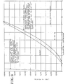
- Figure 9 is a graph on Cartesian co-ordinates comparing the effort of relaxation or dimensional changes on a solid nut with the effect of such changes on an Elephant nut.
- the nut size illustrated is M20 x 1.5.
- the graph has elongation-compression as abscissa and load in pounds as ordinate.
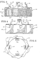
- FIG. 1 shows such a spindle 10, including tapered roller bearings 12, 14 which must, for proper operation, be pre-loaded to a selected value and then maintained pre-loaded at that value for long periods of operation, including operation while subject to vibration and shock.
- a nut of the invention for pre-loading said bearings and maintaining the pre-load during operations of the automobile, is shown at 18.
- nut 18 is run down freely, either by hand or by tool, on the threaded end portion of a spindle bolt 20 until it seats against a washer which transmits the force to a collar or wheel hub 15 splined to the spindle at 16.
- the collar in turn transmits the pre-loading force to the tapered roller bearings 12, 14.
- Such force may be, for example, about 5000 pound-force per sq. inch (34,474.0 kilonewtons per sq. metre or 3.44 hectobars).
- the spindle After the nut seats down, it is tightened by a wrench until the force it applies to the bearing is increased to the selected pre-loading value.
- the spindle is placed in tension, and the tapered roller bearings are pre-loaded in compression. Tightening of nut 18 creates this tension and compression, to a degree determined by the nut tightening torque.
- the total clamp load generated by the nut is in about 17,000 to 22,000 pounds force (75619 to 97860 newtons).
- ratchet lock 32 As the nut 18 is tightened, ratchet lock 32, as shown in Figures 2, 3, 4, 5, 6 and 7, will ratchet, with lugs 34 being freed from the locking slots 26 in cage 22 as it is rotated clockwise.
- the ratchet lock has four fingers 36 integral therewith, composed of spring steel just as is the case with the conical spring segments. These four fingers act to centre the nut 18 on the spindle and, in addition, one of them drops into and engages a slot 38 in the side of the spindle bolt 20 and thus locks the ratchet plate 32 to the spindle bolt 20 against relative rotation, just as soon as the nut 18 is rotated on the bolt by as little as one quarter of a turn.
- the nut 18 can thus be tightened, to the position in which it exerts the selected preload force on taper bearings 12, 14 and then it will be automatically locked by one of the lugs 36 being engaged in slot 38 in the side of the bolt 18. No backward rotation is necessary to form that lock, at exactly the desired pre-load ratchet 32 and lugs 34 thereon enable the nut 18 to be tightened to exactly the desired pre-load and then hold the nut 18 in that position.
- this lock is of course not limited to laminated nuts. It may also be used with solid nuts. It has particular utility however for lock nuts for spindles for front drive automobiles where a high degree of precision and at the same time positive safety is required.
- all parts of the lock nut can be made of spring steel or other spring material and the ratcheting action in the embodiment shown is provided by flexing of the side walls of the nut.
- the flexing need only be very slight and it is found in practice that the usual socket wrench tolerances are sufficient to allow the socket head to fit over the nut, and to rotate the nut, with ratcheting action and consequent side wall flexing without bending.
- the flexing wall action tends to hold the socket on the nut until it is tightened to the point where the ratchet locks in final position and the socket is to be removed.
- the load bearing components of nut 18, as shown in Figures 2 through 7, consist of four conical spring washer segments 40, 42, 44 and 46 which are stacked and aligned to form in effect a laminated nut.
- each cone shaped spring washer segment can be calculated from a formula disclosed in SCHNORR'S Handbook for Disc Springs . (SCHNORR Handbook is published by Adolf Schnorr GmbH & Co. KG D 7032 Sindelfingen 6, Federal Republic of Germany. The 1979 edition is the llth Edition.) As previously stated, the spring discs are not calculated completely to flatten under the designed load; they flex, both up and down as the bolt elongates, contracts, or vibrates.
- the graph of Figure 9 compares the results obtained from a solid nut shown at the left of the Figure and so marked, with the results obtained from a spring disc laminated nut with cone spring washer segments. As will be seen, the bearing pre-loads are maintained over wide ranges of deflection for the spring disc laminated nuts (the two right hand curves) as compared with the curve for the solid mut.
- the bottom cone shaped spring washer segment 72 is of about twice the thickness of the other two segments 68 and 70. This provides a more even distribution of the load, from bolt to nut, over the length of the threaded sections 68, 70 and 72. Thus the nut is less likely to fail by shear of the bolt, stripping of the threads, or by fatigue failures. A substantial improvement relates with no additional cost, simply by the design arrangement.
- FIG. 8 Three laminated segments are shown in Figure 8 but less or more for example two or four could be used.
- An automatic lock plate as shown in Figures through 7 could be added to the nut of Figure 8 if desired.
- Figures 10, 11 and 12 shows a tool, or fixture for disengagement of the nut lock for removal of the nut.
- Pin 82 fits in the centering recess of spindle bolt 20 and an arm 84 extends therefrom over the edge of the bolt and under lug 36.
- lug 36 is lifted out of slot 38, allowing it to be turned, and removed, by a socket wrench which fits over outer cage 22.
- the components, including the conical spring segments, are made of heat treated spring steel as a preferred material.
- a prevailing torque characteristic (interference after counter rotation) is incorporated by means of a non-heat-treatable washer segment in the nut that is permanently flattened by the nut loading. This feature is significant to bearing applications that require bearing clearance adjustment.
- the present invention combines the established formulae used for predicting conical washer behaviour (see SCHNORR'S Handbook for Disc Springs ) with proven load distribution characteristics in nut-bolt joint applications. This combination used in association with other nut bolt tolerance standards allows for design of spring washer segments with predictable behaviour related to bolt loading.
- the nut design as proposed is based upon near uniform washer segment deflection and loading bottom to top.
- the lock mechanism automatically engages in a slot or grooves in the associated bolt, stud or shaft, which can be driven by hand or power tools to desired torque or clamp load requirements, and is positively locked from counter rotation.
- the combination of an automatic self seeking secondary lock mechanism and nut with predictable load-deflection characteristics that contributes spring loading, allows fastener loading of precise joint pre-load with the torque and clamp load tolerances of industry used power tools. This combination is particularly adaptable to loading bearings that require defined pre-load. Further, the design of this invention does not require any secondary adjustment for precise loading.
- the nut required grinding or special surface finishes related to perpendicularity of the axis of the thread to provide uniform interface loading.
- the resilient action of this invention allows the interface surface to self seek for uniform loading; and thirdly, the provision of an inexpensive tool for the purpose of easily defeating the locking device to facilitate removal and reuse.
- Conical spring washer elements 0.078" (1.98 mm) thick with crown of 0.05" (1.27 mm), material 1065-1070 spring steel, ratchet locking mechanism and cage - also spring steel. Cage is 0.036 w (0.9144 mm)
- Lock Mechanism is 0.04" (1.016 mm) thick.
- sample spindle nut described above does not incorporate varied thickness conical spring washer element. This application is utilizing less than half of the nut proof load capacity and is not susceptible to high shear loading.
Landscapes
- Engineering & Computer Science (AREA)
- General Engineering & Computer Science (AREA)
- Mechanical Engineering (AREA)
- Bolts, Nuts, And Washers (AREA)
- Connection Of Plates (AREA)
Applications Claiming Priority (2)
| Application Number | Priority Date | Filing Date | Title |
|---|---|---|---|
| US06/187,833 US4383787A (en) | 1980-09-16 | 1980-09-16 | Free spinning laminated nut with automatic lock |
| US187833 | 1980-09-16 |
Related Parent Applications (3)
| Application Number | Title | Priority Date | Filing Date |
|---|---|---|---|
| EP81902550A Division EP0060271B1 (de) | 1980-09-16 | 1981-09-09 | Leicht drehbare, geschichtete mutter mit automatischer arretierung |
| EP81902550A Division-Into EP0060271B1 (de) | 1980-09-16 | 1981-09-09 | Leicht drehbare, geschichtete mutter mit automatischer arretierung |
| EP81902550.3 Division | 1981-09-09 |
Publications (2)
| Publication Number | Publication Date |
|---|---|
| EP0163832A1 true EP0163832A1 (de) | 1985-12-11 |
| EP0163832B1 EP0163832B1 (de) | 1989-04-19 |
Family
ID=22690656
Family Applications (3)
| Application Number | Title | Priority Date | Filing Date |
|---|---|---|---|
| EP85103470A Expired EP0163833B1 (de) | 1980-09-16 | 1981-09-09 | Geschichtete Sicherungsmutter |
| EP81902550A Expired EP0060271B1 (de) | 1980-09-16 | 1981-09-09 | Leicht drehbare, geschichtete mutter mit automatischer arretierung |
| EP85103469A Expired EP0163832B1 (de) | 1980-09-16 | 1981-09-09 | Geschichtete Sicherungsmutter |
Family Applications Before (2)
| Application Number | Title | Priority Date | Filing Date |
|---|---|---|---|
| EP85103470A Expired EP0163833B1 (de) | 1980-09-16 | 1981-09-09 | Geschichtete Sicherungsmutter |
| EP81902550A Expired EP0060271B1 (de) | 1980-09-16 | 1981-09-09 | Leicht drehbare, geschichtete mutter mit automatischer arretierung |
Country Status (5)
| Country | Link |
|---|---|
| US (1) | US4383787A (de) |
| EP (3) | EP0163833B1 (de) |
| CA (1) | CA1251346A (de) |
| DE (1) | DE3176179D1 (de) |
| WO (1) | WO1982000965A1 (de) |
Families Citing this family (17)
| Publication number | Priority date | Publication date | Assignee | Title |
|---|---|---|---|---|
| CA1297709C (en) * | 1986-12-08 | 1992-03-24 | Pac-Fasteners | Laminated nut with one way installation |
| US4900209A (en) * | 1988-08-04 | 1990-02-13 | Pac-Fasteners | Nut and washer single assembly structure |
| US4940377A (en) * | 1989-08-02 | 1990-07-10 | Pac-Fasteners, A Michigan Partnership | Laminated nut having cage with nested fingers and method of manufacture |
| US5049017A (en) * | 1990-05-21 | 1991-09-17 | Pac Fasteners | Laminated nut with anti-spin off structure and method of making nut |
| US5362110A (en) * | 1991-02-25 | 1994-11-08 | Moeller Manufacturing Co., Inc. | Fluid coupling and fastener capture device |
| ES2143691T3 (es) * | 1996-08-06 | 2000-05-16 | Erreti S N C Di Enrico Tosetti | Tuerca autobloqueante. |
| US5785477A (en) * | 1996-11-07 | 1998-07-28 | Senco Products, Inc. | Laminated internally threaded fastener |
| US5983757A (en) * | 1997-06-02 | 1999-11-16 | Snap-On Technologies, Inc. | Ratchet mechanism with laminated parts and method of making same |
| WO1999032794A1 (en) | 1997-12-19 | 1999-07-01 | Mitts Richard K | Multiple belleville washer nut construction |
| US6015253A (en) * | 1998-11-25 | 2000-01-18 | Illinois Tool Works Inc. | Multiple washer nut and method of making |
| JP2004216489A (ja) * | 2003-01-14 | 2004-08-05 | Kobayashi Kogu Seisakusho:Kk | 手動式ケーブルカッター |
| WO2005079949A1 (en) * | 2004-02-17 | 2005-09-01 | Stanadyne Corporation | Drain valve insert |
| US20080193259A1 (en) * | 2007-02-12 | 2008-08-14 | Hill Ross S | Laminated wheel lug nut |
| US7789608B2 (en) * | 2007-02-13 | 2010-09-07 | Illinois Tool Works Inc. | Laminated nut with tension indicator |
| KR101027753B1 (ko) * | 2008-12-09 | 2011-04-08 | 이상철 | 풀림방지 볼트너트 결합체 |
| US20120237312A1 (en) * | 2011-03-14 | 2012-09-20 | Thomas John Widule | Torque-limiting nut assembly |
| US11204056B2 (en) * | 2016-06-30 | 2021-12-21 | Smc Corporation | Nut |
Citations (5)
| Publication number | Priority date | Publication date | Assignee | Title |
|---|---|---|---|---|
| US1813640A (en) * | 1929-05-29 | 1931-07-07 | Rossetti George | Nut lock |
| US2382748A (en) * | 1939-08-02 | 1945-08-14 | Schuttler Paul | Nut |
| US2581641A (en) * | 1946-01-29 | 1952-01-08 | Forgaard Harcourt Lester | Nut |
| US3461935A (en) * | 1967-02-01 | 1969-08-19 | Giulio Monticelli | Resilient self-blocking nut |
| FR2397558A1 (fr) * | 1977-07-14 | 1979-02-09 | Norma Spa | Ecrou autobloquant et procede pour sa fabrication |
Family Cites Families (5)
| Publication number | Priority date | Publication date | Assignee | Title |
|---|---|---|---|---|
| US712905A (en) * | 1902-03-03 | 1902-11-04 | James W H Cannon | Nut-lock. |
| US1293755A (en) * | 1918-12-11 | 1919-02-11 | Isom A Gorden | Nut-lock. |
| US1755807A (en) * | 1929-04-06 | 1930-04-22 | George I Boles | Lock nut |
| FR675066A (fr) * | 1929-05-15 | 1930-02-05 | Ecrou Indesserrable Rex L | Perfectionnements apportés aux dispositifs pour rendre les écrous indesserrables |
| US3233262A (en) * | 1963-02-18 | 1966-02-08 | Vollman Walter | Method of producing locknuts by assembling laminae in a housing |
-
1980
- 1980-09-16 US US06/187,833 patent/US4383787A/en not_active Expired - Lifetime
-
1981
- 1981-09-09 EP EP85103470A patent/EP0163833B1/de not_active Expired
- 1981-09-09 EP EP81902550A patent/EP0060271B1/de not_active Expired
- 1981-09-09 EP EP85103469A patent/EP0163832B1/de not_active Expired
- 1981-09-09 DE DE8181902550T patent/DE3176179D1/de not_active Expired
- 1981-09-09 WO PCT/US1981/001199 patent/WO1982000965A1/en not_active Ceased
- 1981-09-15 CA CA000385934A patent/CA1251346A/en not_active Expired
Patent Citations (5)
| Publication number | Priority date | Publication date | Assignee | Title |
|---|---|---|---|---|
| US1813640A (en) * | 1929-05-29 | 1931-07-07 | Rossetti George | Nut lock |
| US2382748A (en) * | 1939-08-02 | 1945-08-14 | Schuttler Paul | Nut |
| US2581641A (en) * | 1946-01-29 | 1952-01-08 | Forgaard Harcourt Lester | Nut |
| US3461935A (en) * | 1967-02-01 | 1969-08-19 | Giulio Monticelli | Resilient self-blocking nut |
| FR2397558A1 (fr) * | 1977-07-14 | 1979-02-09 | Norma Spa | Ecrou autobloquant et procede pour sa fabrication |
Also Published As
| Publication number | Publication date |
|---|---|
| EP0060271A4 (de) | 1984-09-05 |
| EP0163833A1 (de) | 1985-12-11 |
| EP0163833B1 (de) | 1989-04-19 |
| EP0060271A1 (de) | 1982-09-22 |
| US4383787A (en) | 1983-05-17 |
| EP0163832B1 (de) | 1989-04-19 |
| CA1251346A (en) | 1989-03-21 |
| CA1259830C (de) | 1989-09-26 |
| DE3176179D1 (en) | 1987-06-19 |
| EP0060271B1 (de) | 1987-05-13 |
| WO1982000965A1 (en) | 1982-04-01 |
Similar Documents
| Publication | Publication Date | Title |
|---|---|---|
| EP0060271B1 (de) | Leicht drehbare, geschichtete mutter mit automatischer arretierung | |
| AU644285B2 (en) | Locking fastener | |
| US6019556A (en) | Locking fastener assembly | |
| US7128511B2 (en) | Fastener | |
| US4930962A (en) | Nut and stud assembly | |
| US20020015628A1 (en) | Fastener assembly including a screw element and a supporting element | |
| US3648749A (en) | Fastener assembly with locking capabilities | |
| US3438417A (en) | Canting lock bolt | |
| US4854794A (en) | Connector of the nut-and-bolt type | |
| CZ298278B6 (cs) | Rozebíratelný spojovací element | |
| EP0130304B1 (de) | Doppelte Sicherungsmutter-Einrichtung und Verbindung der Sicherungsmutter-Einrichtung mit einem Bolzen | |
| US20130164093A1 (en) | Fastener | |
| US5017079A (en) | Laminated nut with one way installation | |
| US3329057A (en) | Threaded fastener device | |
| CA2349554C (en) | Fastener | |
| CA1251347A (en) | Free spinning laminated nut with automatic lock | |
| CN211778433U (zh) | 一款防止松动的新型螺母 | |
| EP4121662B1 (de) | Befestigungsanordnung mit verriegelungsgewinde | |
| CN111997983A (zh) | 一种止动槽螺母防松装置 | |
| WO2026003888A1 (en) | Safety anti-loosening screw–nut system | |
| WO1999002870A1 (en) | Torque limiting device |
Legal Events
| Date | Code | Title | Description |
|---|---|---|---|
| PUAI | Public reference made under article 153(3) epc to a published international application that has entered the european phase |
Free format text: ORIGINAL CODE: 0009012 |
|
| 17P | Request for examination filed |
Effective date: 19850402 |
|
| AC | Divisional application: reference to earlier application |
Ref document number: 60271 Country of ref document: EP |
|
| AK | Designated contracting states |
Designated state(s): DE FR GB |
|
| 17Q | First examination report despatched |
Effective date: 19870626 |
|
| GRAA | (expected) grant |
Free format text: ORIGINAL CODE: 0009210 |
|
| AC | Divisional application: reference to earlier application |
Ref document number: 60271 Country of ref document: EP |
|
| AK | Designated contracting states |
Kind code of ref document: B1 Designated state(s): DE FR GB |
|
| REF | Corresponds to: |
Ref document number: 3177035 Country of ref document: DE Date of ref document: 19890524 |
|
| ET | Fr: translation filed | ||
| PLBE | No opposition filed within time limit |
Free format text: ORIGINAL CODE: 0009261 |
|
| STAA | Information on the status of an ep patent application or granted ep patent |
Free format text: STATUS: NO OPPOSITION FILED WITHIN TIME LIMIT |
|
| 26N | No opposition filed | ||
| PGFP | Annual fee paid to national office [announced via postgrant information from national office to epo] |
Ref country code: FR Payment date: 20000822 Year of fee payment: 20 |
|
| PGFP | Annual fee paid to national office [announced via postgrant information from national office to epo] |
Ref country code: GB Payment date: 20000825 Year of fee payment: 20 |
|
| PGFP | Annual fee paid to national office [announced via postgrant information from national office to epo] |
Ref country code: DE Payment date: 20000828 Year of fee payment: 20 |
|
| PG25 | Lapsed in a contracting state [announced via postgrant information from national office to epo] |
Ref country code: GB Free format text: LAPSE BECAUSE OF EXPIRATION OF PROTECTION Effective date: 20010908 |
|
| REG | Reference to a national code |
Ref country code: GB Ref legal event code: PE20 Effective date: 20010908 |