EP0163885A1 - Dispositif de segmentation de lignes - Google Patents
Dispositif de segmentation de lignes Download PDFInfo
- Publication number
- EP0163885A1 EP0163885A1 EP85104779A EP85104779A EP0163885A1 EP 0163885 A1 EP0163885 A1 EP 0163885A1 EP 85104779 A EP85104779 A EP 85104779A EP 85104779 A EP85104779 A EP 85104779A EP 0163885 A1 EP0163885 A1 EP 0163885A1
- Authority
- EP
- European Patent Office
- Prior art keywords
- memory
- segments
- segment
- comparator
- memories
- Prior art date
- Legal status (The legal status is an assumption and is not a legal conclusion. Google has not performed a legal analysis and makes no representation as to the accuracy of the status listed.)
- Withdrawn
Links
Images



Classifications
-
- G—PHYSICS
- G06—COMPUTING OR CALCULATING; COUNTING
- G06V—IMAGE OR VIDEO RECOGNITION OR UNDERSTANDING
- G06V10/00—Arrangements for image or video recognition or understanding
- G06V10/40—Extraction of image or video features
-
- G—PHYSICS
- G06—COMPUTING OR CALCULATING; COUNTING
- G06V—IMAGE OR VIDEO RECOGNITION OR UNDERSTANDING
- G06V10/00—Arrangements for image or video recognition or understanding
- G06V10/40—Extraction of image or video features
- G06V10/46—Descriptors for shape, contour or point-related descriptors, e.g. scale invariant feature transform [SIFT] or bags of words [BoW]; Salient regional features
-
- G—PHYSICS
- G06—COMPUTING OR CALCULATING; COUNTING
- G06V—IMAGE OR VIDEO RECOGNITION OR UNDERSTANDING
- G06V10/00—Arrangements for image or video recognition or understanding
- G06V10/40—Extraction of image or video features
- G06V10/46—Descriptors for shape, contour or point-related descriptors, e.g. scale invariant feature transform [SIFT] or bags of words [BoW]; Salient regional features
- G06V10/469—Contour-based spatial representations, e.g. vector-coding
Definitions
- the invention relates to an arrangement for segmentation, classification and approximation of lines, which are given by a point sequence and each point is determined by its coordinates and the directional angle.
- the sensors previously available on the market depict the three-dimensional scene containing the workpieces in a binary image in which the workpiece to be recognized stands out as a white surface from the black background or vice versa.
- This areal pattern which describes the silhouette of the workpiece, is now evaluated using comparatively simple algorithms (for example, calculation of the center of gravity for determining the position, determination of the axes of inertia or "polar check" for determining the rotational position).
- This type of evaluation assumes that different workpieces do not touch or overlap, but on the other hand that a workpiece does not disintegrate into several areas due to the binarization.
- the gray-scale image in which edges are visible must therefore be assumed.
- the invention has for its object to develop an adaptable to different circumstances, sufficiently fast, economical sensor system for the detection and inspection of overlapping, not isolated workpieces.
- the aim of the segmentation described here is to divide the course of any line, for example the circumference of a workpiece, into defined pieces (segments with defined properties, for example straight lines, circular pieces and corners) and to describe these pieces in an equation form .
- These lines are first searched for and tracked by a so-called edge tracking.
- edge tracking With the help of an area filter, a gradient image is generated from the gray-scale image of a scene. Lines are extracted from this gradient image.
- Such an arrangement is based on the assumption that technical objects can generally be described by their edges and the edges by features such as straight lines, circles, arcs and corners. Such an arrangement is the subject of patent application P 34 15 467.1.
- gray value or gray value differences or sizes that can be derived from gray values (mean gray value of a surface, textures, colors) for recognition.
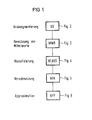
- the input data of the selected arrangement come from edge tracking in the form of a line list into a rough segmentation GS, which is explained in more detail in FIG.
- This rough segmentation is followed by a mean value calculation MWB, which is the subject of FIG. 3.
- the CLASS classification is carried out particularly in FIG. 4.
- the fusion VER is described in detail in FIG. 5 and the approximation APP in FIG. 6.
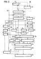
- Explanation of FIG. 2: 1 denotes a differentiator which differentiates the input data, that is the directional angle ⁇ of each point on a line, and which smoothes the differentiated signals for interference suppression.
- the order differentiation - smoothing or smoothing - differentiation is arbitrary.
- the result is the angle difference ⁇ of two successive points in a line.
- This differentiator consists, for example, of a subtractor, stores and adders.
- a class detector 2 is provided, which is implemented, for example, by a memory.
- classes are to be understood as curvature classes. However, it could also be constructed from a comparison angle sensor and a comparator.
- the class detectors 3 and 4 follow the class detector 2 for class comparison of successive points.
- Class changes are recognized by a comparator 5.
- the memories 6 and 7 are used with a comparator 8 for trend detection. The sequence of changes is called the trend.
- a limit length memory 9 is connected to the comparator 8.
- the comparator 8 and the limit length memory 9 are, for example, in a PROM realized. With each class change, the comparator 5 also resets a length counter 10, which counts successive points of the same class.
- a length comparator 11 follows the limit length memory 9 and the length counter 10 and classifies line segments of the same class above the limit length as independent segments.
- the blocks 8, 9 and 11 described can, for example, also be combined in a PROM of a suitable size.
- the trend detection 8, the length comparator 11 and the class memory 4 result in the description of a current section, which is stored in a memory 12a and 12b.
- 12a contains the coding for the tendency and the identifier for independent sections.
- 12b contains the class of this section.
- a memory 13 contains the part of the description of the previous section that was stored in FIG. 12a.
- a comparison class is stored in a memory 14.
- a programmable memory 15 contains the algorithm for the entry in a segment point memory 17 and the eventual transfer of the class from the memory 12b into the comparison class memory 14.
- the clock synchronization 16 is connected between the memory 15 and the memory 17 and effects the changeover of the change addresses memories 19 and 20.
- a point counter 18 is incremented with each line point. The counter reading is transferred to the memory 19 with each class change. The previous change is in the memory 20.
- the segment point decision implemented in the memory 15 is controlled from the data of the memory 12a, the memory 13 and the result of a class difference comparator 21. With 22 the switching between the memories 19 and 20 is designated.
- the point clock is supplied via line 23.
- a logic circuit 24 forms. from the point cycle and the change output of the Kompara tors 5 the class clock 26. It is formed with every class change.
- Each point is therefore determined by its directional angle ⁇ , the coordinates x, y and a direction code RK.
- the directional angle ⁇ is the tangent angle or the normal angle offset by 90 °.
- line segments appear at the output of the differentiator 1 (FIG. 2) as lines which coincide with the abscissa and circles as a parallel to the abscissa. The distance between the two is inversely proportional to the radius. Corners appear as needles. The transition between corners and small circles is fluid.
- the difference angles in the class detector 2 are divided into curvature classes.
- a so-called class list is created. All line points where a class change is made and the associated classes are noted in it.
- the class change is recognized by comparing the contents of the memories 3 and 4 in the comparator 5.
- the address of the change in the two most recent elements of the Class lists are stored in memories 19 and 20, the type of change in memories 6 and 7 and the class itself is recorded in memory 12a.
- the class list is shown in the following example:
- This code is referred to as a tendency and is recognized in the comparator 8, which is controlled by the two change memories 6, 7.
- Parts that are not marked as independent may be fused together, but independent parts of different classes may not. This process takes place in the "segment point decision" 15 and will be explained later.
- the minimum length for independence (in points) is, for example
- a variant is indicated in dashed lines in FIG. 2 which, after the later evaluation according to FIG. 3, enables an exact determination of the radius.
- a memory 25 for example PROM
- the difference angle ⁇ becomes the previous one transition angle ⁇ and the directional code RK also contained in the line list, the grid error of ⁇ -canceled, that is to say the curvature of the grid curve is exactly determined.
- the curvature is the reciprocal of the radius of curvature and thus the radius is determined.
- the corrected curvature is subsequently used in the segmentation instead of ⁇ .
- the totalization of the arc length is omitted in the later calculation of the mean values (FIG. 3).
- the radius calculation is further reduced to the reciprocal formation of the mean value of ⁇ .
- the direction code indicates the preceding grid point from which the line point was driven.
- the direction code corresponds to the Freeman chain code and specifies the direction of the eight neighboring points of a point in an orthogonal grid.
- the sum formation, the maximum value determination for ⁇ and, if appropriate, the mean value formation take place over a segment length. These values are required for the following classification and approximation of the segments into straight pieces, circular segments, corners and parts that cannot yet be defined with sufficient accuracy.
- the segment boundaries come from the segment point memory 17 of FIG. 2 (for example RAM) and, in parallel, the data to be processed via an input synchronization memory 30 (for example register).
- This data is the directional angle ⁇ , the coordinates x, y and the tracking direction code.
- the sum of the coordinates x, y, via gate 31, ⁇ cos ⁇ (for example via PROM 32), ⁇ sin ⁇ , (for example via PROM 33) the L arc length (for example via PROM 34) and the sum of the difference angle ⁇ (for example via register 35, subtractor 36) are formed.
- the square of the maximum ⁇ 2 PROM 41, memory 42, comparator 43
- An adder 37 in conjunction with an accumulator 38 (for example a register) is used to form the sum.
- a part of the sums formed in 37, 38 is normalized to the segment length by means of the counter 39 and the divider 40 (for example PROM with reciprocal of the counter reading and multiplier), that is to say the mean value over a segment is formed.
- a buffer entry controller 44 (for example a programmable logic array) initiates the successive entry of the calculated values into the output memories 47, 48 (RAM).
- the output memories are switched as a removable buffer. Each memory contains several subaddresses under one address for recording the individual calculation results. It could also be divided into several areas.
- a control unit 45 (for example a microprocessor) controls the overall process and the selection of the input data and the data paths within the circuit.
- the result of the addition is continuously divided by the counter reading in 39.
- the Divisionsesge.bnis is constantly entered in one of the output memories 47 or 48.
- the last calculated value per segment is always in the output memory. All previously calculated values are overwritten.
- the accumulator 38 and the counter 39 are cleared at each segment boundary that is supplied by the memory 17.
- the address of the output memories 47 or 48 is then increased.
- the intermediate results do not have to be constantly entered in the output memory. However, this simplifies the final treatment.
- the arc length ⁇ and the sum "n" length of a segment is not divided by the segment length, which is in the counter 30. This is achieved, for example, by predefining a counter reading "1".
- the coordinates x and y do not need to be specially transformed. They are switched directly to adder 37 via gate 31.
- the values from 47 and 48 from FIG. 3 are successively transferred to the buffer stores 51 to 54.
- the contents of the memories 51 and 52- are divided into 55 and the division result in the comparator 57 is compared with the threshold in a memory 56.
- the content of the memory 52 is compared with two thresholds in the memory 58 by means of the comparator 59.
- the contents of the memories 53 and 54 are compared with the thresholds in the memories 60 and 62 by means of the comparators 61 and 63, respectively.
- the five comparison results from the comparators 57, 59 (two outputs), 61 and 63 are linked in a logic circuit 64 (for example freely programmable memory or PROM or fixed logic combination).
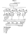
- the line pieces determined in the arrangements according to FIGS. 1 and 2 appear, for example, classified as a straight line, circular arc, corner or undefined parts and are stored in the segment point memory 17, FIG. 2.
- the classification code is described in Figure 4.
- the thresholds in the memories 56, 58, 60 and 62 are set depending on the expected recognition result.
- the threshold in memory 56 is denoted by S1, the thresholds in memory 58 by S2 and S3, the threshold in memory 60 by S4 and the threshold in memory 62 by S5.
- the arrangement according to FIG. 5 serves to fuse segments classified in the arrangement according to FIG. 4.
- three memories 70-72 are provided, in which the segment class codes of three immediately successive segments, which were generated in the circuit 64 (FIG. 4) and temporarily stored in 17 (FIG. 2), are stored.
- the outputs of the memories 70-72 are processed in a circuit 73, for example memory or PROM, and give an indication of a calculation rule which is executed in a processor 74.
- 75-77 are memories for parameter sets which are assigned to the segment class code memories 70-72.
- a switch 78 enables the memory 72 to be loaded either from the input data or depending on the result of the merge operation in the processor 74.
- memory 77 can be loaded either directly from memory 76 or from processor 74.
- the mode of operation of the arrangement according to FIG. 4 is explained using an example.
- the following segments for example, are delivered from the classification, the sequence being viewed counterclockwise from the starting point S.
- memories 70-72 are cleared.
- the individual segments are pushed through the memories in the manner of a shift register. Processing begins as soon as all the memories are filled.
- the associated parameter sets are stored in memories 75-77, namely for E1 in 75, for G2 in 76 and for G1 in 77. It is now checked whether suitable segments for a merger are stored in memories 70-72.
- the classification codes which each consist of 2 bits, for example, are present at the output of each memory (see classification code in connection with the description of FIG. 4).
- the three codes address the memory 73, in which a further address is stored in the addressed memory cell, which leads to the valid processing instruction for the present case in the program memory of the processor 74.
- the memory 73 can of course also be implemented as a logical link.
- the processing instructions in processor 74 usually check the middle segment (memory 71) with its neighboring segments (70, 72) for the possibility of merging.
- the rule is, for example: Check the straight line G1 and the straight line G2 for fusibility, that is, a new segment is to be formed from 76, 77 with the parameters. It is then examined whether this new segment still meets the straight line criteria in this example according to arrangement 4. If this is the case, the straight lines G1 and G2 are combined. However, if the criterion for the straight line is not met, the original segments are retained.
- the switch 78 is switched to the dashed position and the memory 72 is optionally rewritten with a new classification code from the processor 74 and the combined parameters of the two original segments G1 G2 are transferred to the memory 77.
- a new element is made up in the memory 70 and the old content of the memory 70 in 71 is adopted. This overwrites the previous content of 71.
- the same code as before is stored in the memory 72 after the merger, because two straight lines have been merged into one straight line.
- the memories 75-76 for the parameter sets are treated similarly.
- the combination G1-2 in 72, E1 in 71 and G3 in 70 is now available.
- the requirement is not to merge.
- the switch 78 is brought into the vertical position and the shift register function is restored.
- the processor 74 thus causes a new segment to be accepted into the memories 70 and 75 and a segment to be released from the memories 72 and 77 for further processing.
- the remaining segments are examined in an analogous manner.
- a new merger is only carried out when the segment K2 in the memory 71 or 76 and K1 in the memory 72 or 77 and G6 is in 70 or 75.
- it is checked whether the curvatures match within a certain tolerance. If this is the case, then the two segments are merged. If the curvatures do not match, they remain separate.
- the undefined segments according to arrangement 4 are short, slightly curved line segments that cannot be clearly classified. you will be always merged with neighboring segments. At the end of the merge operation, there are no more indefinite segments.
- a further possibility for the parameter calculation of segments to be merged is as follows: the boundary marking between two merged segments is deleted from the segment memory 17 and after the merging operation has been completed a new calculation process for this line in the arrangement according to FIG. 3 is started with these new limits.
- FIG. 6 An arrangement for approximation is shown schematically in FIG. 6.
- the aim of this approximation is to represent the determined line segments in the simplest possible mathematical form.
- the input data for the approximation are contained in the output memories 47, 48 (FIG. 2, segment parameters) and 17 (FIG. 1, classification code).
- 80 is an arithmetic unit or a table
- 81 is also an arithmetic unit
- 82 is another arithmetic unit.
- the arithmetic units 81 and 82 are switched on via a switch 83 if required.
- 84 is a memory for storing the calculated values.
- straight lines are defined by their center coordinates by their orientation arctan and determined their length. Only the orientation is additionally determined from the parameter set (contained in 47, 48) by means of the arithmetic unit 80.
- Corners are represented by , by the arctan orientation and their opening angle ⁇ .
- the parameter set (including in 47, 48) also only the orientation was additionally determined using arithmetic unit 80.
- Circle segments are represented by their center coordinates, by the radius, by the arctan orientation and their opening angle ⁇ . If a segment has been classified as a circle segment in the memory 17, then the arithmetic units for radius 81 and center point 82 are additionally switched on via the switch 83.
- the radius is calculated using the following formula:
- the center coordinates are calculated as follows:
- the final parameters are partly transferred from the parameter set in 47 and 48 directly into the memory 84 and partly written into the memory 84 by the arithmetic units 80-82 and are then available for further processing, sorted by type.
- the control unit 85 is used to switch through the data paths and to allocate the memory 84. It is implemented, for example, by programmable components and memory or by a microprocessor.
Landscapes
- Engineering & Computer Science (AREA)
- Physics & Mathematics (AREA)
- General Physics & Mathematics (AREA)
- Multimedia (AREA)
- Theoretical Computer Science (AREA)
- Computer Vision & Pattern Recognition (AREA)
- Image Analysis (AREA)
Applications Claiming Priority (2)
| Application Number | Priority Date | Filing Date | Title |
|---|---|---|---|
| DE3417545 | 1984-05-11 | ||
| DE3417545 | 1984-05-11 |
Publications (1)
| Publication Number | Publication Date |
|---|---|
| EP0163885A1 true EP0163885A1 (fr) | 1985-12-11 |
Family
ID=6235618
Family Applications (1)
| Application Number | Title | Priority Date | Filing Date |
|---|---|---|---|
| EP85104779A Withdrawn EP0163885A1 (fr) | 1984-05-11 | 1985-04-19 | Dispositif de segmentation de lignes |
Country Status (3)
| Country | Link |
|---|---|
| US (1) | US4731858A (fr) |
| EP (1) | EP0163885A1 (fr) |
| JP (1) | JPS60245087A (fr) |
Cited By (4)
| Publication number | Priority date | Publication date | Assignee | Title |
|---|---|---|---|---|
| EP0303623A4 (en) * | 1986-04-14 | 1991-09-04 | Vartec Corporation | Electronic inspection system and methods of inspection |
| FR2661999A1 (fr) * | 1990-05-11 | 1991-11-15 | Univ Alsace | Procede et dispositif d'identification de formes ou de profils. |
| FR2663139A1 (fr) * | 1990-06-08 | 1991-12-13 | Philips Electronique Lab | Dispositif de reconnaissance automatique d'objets. |
| EP0422245B1 (fr) * | 1989-04-04 | 1998-01-14 | Ntt Data Communications Systems Corporation | Appareil de reconnaissance |
Families Citing this family (47)
| Publication number | Priority date | Publication date | Assignee | Title |
|---|---|---|---|---|
| US5109431A (en) * | 1988-09-22 | 1992-04-28 | Hitachi, Ltd. | Pattern discrimination method and apparatus using the same |
| US6067379A (en) * | 1988-12-09 | 2000-05-23 | Cognex Corporation | Method and apparatus for locating patterns in an optical image |
| JP3001966B2 (ja) * | 1990-11-30 | 2000-01-24 | 株式会社リコー | 文字認識用辞書の作成方法 |
| CA2049866C (fr) * | 1990-12-28 | 1998-06-30 | Raymond L. Higgins | Systeme et methode de reconnaissance optique de caracteres de codes a barres |
| JP2691101B2 (ja) * | 1992-03-05 | 1997-12-17 | インターナショナル・ビジネス・マシーンズ・コーポレイション | 手書き入力方法及び入力装置 |
| US5267326A (en) * | 1992-03-31 | 1993-11-30 | Eastman Kodak Company | Bitmap image segmentation using a charge model for pixels |
| US5638462A (en) * | 1993-12-24 | 1997-06-10 | Nec Corporation | Method and apparatus for recognizing graphic forms on the basis of elevation angle data associated with sequence of points constituting the graphic form |
| US6026176A (en) | 1995-07-25 | 2000-02-15 | Cognex Corporation | Machine vision methods and articles of manufacture for ball grid array inspection |
| US5764788A (en) * | 1995-08-31 | 1998-06-09 | Macmillan Bloedel Limited | Strand orientation sensing |
| JPH09138471A (ja) * | 1995-09-13 | 1997-05-27 | Fuji Photo Film Co Ltd | 特定形状領域の抽出方法、特定領域の抽出方法及び複写条件決定方法 |
| US5751853A (en) * | 1996-01-02 | 1998-05-12 | Cognex Corporation | Locating shapes in two-dimensional space curves |
| US5872870A (en) * | 1996-02-16 | 1999-02-16 | Cognex Corporation | Machine vision methods for identifying extrema of objects in rotated reference frames |
| US5909504A (en) * | 1996-03-15 | 1999-06-01 | Cognex Corporation | Method of testing a machine vision inspection system |
| US6298149B1 (en) | 1996-03-21 | 2001-10-02 | Cognex Corporation | Semiconductor device image inspection with contrast enhancement |
| US6259827B1 (en) | 1996-03-21 | 2001-07-10 | Cognex Corporation | Machine vision methods for enhancing the contrast between an object and its background using multiple on-axis images |
| US5978502A (en) * | 1996-04-01 | 1999-11-02 | Cognex Corporation | Machine vision methods for determining characteristics of three-dimensional objects |
| US6137893A (en) * | 1996-10-07 | 2000-10-24 | Cognex Corporation | Machine vision calibration targets and methods of determining their location and orientation in an image |
| US5960125A (en) | 1996-11-21 | 1999-09-28 | Cognex Corporation | Nonfeedback-based machine vision method for determining a calibration relationship between a camera and a moveable object |
| US5953130A (en) * | 1997-01-06 | 1999-09-14 | Cognex Corporation | Machine vision methods and apparatus for machine vision illumination of an object |
| US6075881A (en) * | 1997-03-18 | 2000-06-13 | Cognex Corporation | Machine vision methods for identifying collinear sets of points from an image |
| US5974169A (en) * | 1997-03-20 | 1999-10-26 | Cognex Corporation | Machine vision methods for determining characteristics of an object using boundary points and bounding regions |
| US6141033A (en) * | 1997-05-15 | 2000-10-31 | Cognex Corporation | Bandwidth reduction of multichannel images for machine vision |
| US6608647B1 (en) | 1997-06-24 | 2003-08-19 | Cognex Corporation | Methods and apparatus for charge coupled device image acquisition with independent integration and readout |
| US5978080A (en) * | 1997-09-25 | 1999-11-02 | Cognex Corporation | Machine vision methods using feedback to determine an orientation, pixel width and pixel height of a field of view |
| US6038351A (en) * | 1997-10-28 | 2000-03-14 | Cash Management Solutions | Apparatus and method for multi-entity, mixed document environment document identification and processing |
| US6025854A (en) * | 1997-12-31 | 2000-02-15 | Cognex Corporation | Method and apparatus for high speed image acquisition |
| US6236769B1 (en) | 1998-01-28 | 2001-05-22 | Cognex Corporation | Machine vision systems and methods for morphological transformation of an image with zero or other uniform offsets |
| US6282328B1 (en) | 1998-01-28 | 2001-08-28 | Cognex Corporation | Machine vision systems and methods for morphological transformation of an image with non-uniform offsets |
| US6215915B1 (en) | 1998-02-20 | 2001-04-10 | Cognex Corporation | Image processing methods and apparatus for separable, general affine transformation of an image |
| US6381375B1 (en) | 1998-02-20 | 2002-04-30 | Cognex Corporation | Methods and apparatus for generating a projection of an image |
| US6381366B1 (en) | 1998-12-18 | 2002-04-30 | Cognex Corporation | Machine vision methods and system for boundary point-based comparison of patterns and images |
| US6687402B1 (en) | 1998-12-18 | 2004-02-03 | Cognex Corporation | Machine vision methods and systems for boundary feature comparison of patterns and images |
| US6901171B1 (en) | 1999-04-30 | 2005-05-31 | Cognex Technology And Investment Corporation | Methods and apparatuses for refining groupings of edge points that represent a contour in an image |
| US6697535B1 (en) | 1999-04-30 | 2004-02-24 | Cognex Technology And Investment Corporation | Method for refining a parameter of a contour in an image |
| US6684402B1 (en) | 1999-12-01 | 2004-01-27 | Cognex Technology And Investment Corporation | Control methods and apparatus for coupling multiple image acquisition devices to a digital data processor |
| US6748104B1 (en) | 2000-03-24 | 2004-06-08 | Cognex Corporation | Methods and apparatus for machine vision inspection using single and multiple templates or patterns |
| US7006669B1 (en) | 2000-12-31 | 2006-02-28 | Cognex Corporation | Machine vision method and apparatus for thresholding images of non-uniform materials |
| US7146057B2 (en) * | 2002-07-10 | 2006-12-05 | Northrop Grumman Corporation | System and method for image analysis using a chaincode |
| US7149356B2 (en) * | 2002-07-10 | 2006-12-12 | Northrop Grumman Corporation | System and method for template matching of candidates within a two-dimensional image |
| US7116823B2 (en) | 2002-07-10 | 2006-10-03 | Northrop Grumman Corporation | System and method for analyzing a contour of an image by applying a Sobel operator thereto |
| EP1755399A2 (fr) * | 2004-05-13 | 2007-02-28 | Bayer CropScience AG | Procede ameliorant la croissance de plantes |
| US7639861B2 (en) | 2005-09-14 | 2009-12-29 | Cognex Technology And Investment Corporation | Method and apparatus for backlighting a wafer during alignment |
| US8111904B2 (en) * | 2005-10-07 | 2012-02-07 | Cognex Technology And Investment Corp. | Methods and apparatus for practical 3D vision system |
| US8162584B2 (en) * | 2006-08-23 | 2012-04-24 | Cognex Corporation | Method and apparatus for semiconductor wafer alignment |
| US8005262B2 (en) * | 2007-07-16 | 2011-08-23 | Hugh Griffin | System and method for video object identification |
| DE102008049859B4 (de) * | 2008-10-01 | 2013-03-21 | Panasonic Electric Works Europe Ag | Verfahren und Prüfsystem zur optischen Prüfung einer Kontur eines Prüfobjekts |
| DE102008049858B4 (de) * | 2008-10-01 | 2013-07-11 | Panasonic Electric Works Europe Ag | Verfahren und Prüfsystem zur optischen Prüfung eines Prüfobjekts |
Citations (2)
| Publication number | Priority date | Publication date | Assignee | Title |
|---|---|---|---|---|
| US3268864A (en) * | 1963-03-18 | 1966-08-23 | Apparatus for feature recognition of symbols | |
| GB2108306A (en) * | 1981-10-16 | 1983-05-11 | Tokyo Shibaura Electric Co | Pattern recognition apparatus and method |
Family Cites Families (2)
| Publication number | Priority date | Publication date | Assignee | Title |
|---|---|---|---|---|
| JPS5926064B2 (ja) * | 1979-09-10 | 1984-06-23 | 工業技術院長 | 輪郭画像の特徴抽出装置 |
| US4365235A (en) * | 1980-12-31 | 1982-12-21 | International Business Machines Corporation | Chinese/Kanji on-line recognition system |
-
1985
- 1985-04-19 EP EP85104779A patent/EP0163885A1/fr not_active Withdrawn
- 1985-04-24 US US06/726,763 patent/US4731858A/en not_active Expired - Fee Related
- 1985-05-10 JP JP60099445A patent/JPS60245087A/ja active Pending
Patent Citations (2)
| Publication number | Priority date | Publication date | Assignee | Title |
|---|---|---|---|---|
| US3268864A (en) * | 1963-03-18 | 1966-08-23 | Apparatus for feature recognition of symbols | |
| GB2108306A (en) * | 1981-10-16 | 1983-05-11 | Tokyo Shibaura Electric Co | Pattern recognition apparatus and method |
Non-Patent Citations (1)
| Title |
|---|
| PROCEEDINGS OF THE IEEE, Computer Society Conference on Pattern Recognition and Image Processing, 14.-17. Juni 1982, Las Vegas, Nevada, US; Seiten 165-170, IEEE; D. D'Amato et al.: "High speed pattern recognition system for alphanumeric handprinted characters" * |
Cited By (4)
| Publication number | Priority date | Publication date | Assignee | Title |
|---|---|---|---|---|
| EP0303623A4 (en) * | 1986-04-14 | 1991-09-04 | Vartec Corporation | Electronic inspection system and methods of inspection |
| EP0422245B1 (fr) * | 1989-04-04 | 1998-01-14 | Ntt Data Communications Systems Corporation | Appareil de reconnaissance |
| FR2661999A1 (fr) * | 1990-05-11 | 1991-11-15 | Univ Alsace | Procede et dispositif d'identification de formes ou de profils. |
| FR2663139A1 (fr) * | 1990-06-08 | 1991-12-13 | Philips Electronique Lab | Dispositif de reconnaissance automatique d'objets. |
Also Published As
| Publication number | Publication date |
|---|---|
| US4731858A (en) | 1988-03-15 |
| JPS60245087A (ja) | 1985-12-04 |
Similar Documents
| Publication | Publication Date | Title |
|---|---|---|
| EP0163885A1 (fr) | Dispositif de segmentation de lignes | |
| DE69327928T2 (de) | Vorrichtung zur Kodierung von unbeweglichen Bildern | |
| DE19831413C2 (de) | Bildverarbeitungsverfahren und Vorrichtungen zur Erkennung von Objekten im Verkehr | |
| DE102018215055A1 (de) | Verfahren zum Bestimmen einer Spurwechselangabe eines Fahrzeugs, ein computerlesbares Speichermedium und ein Fahrzeug | |
| DE10043460C2 (de) | Auffinden von Körperpartien durch Auswerten von Kantenrichtungsinformation | |
| DE102017220307A1 (de) | Vorrichtung und Verfahren zum Erkennen von Verkehrszeichen | |
| EP0474304B1 (fr) | Agencement de circuit pour la reconnaissance d'un visage humain | |
| DE102012000459A1 (de) | Verfahren zur Objektdetektion | |
| EP4505211A1 (fr) | Procédé de prédiction de trajectoires d'objets | |
| DE10145608B4 (de) | Modellbasierte Objektklassifikation und Zielerkennung | |
| EP1709587A1 (fr) | Systeme de traitement image | |
| DE102017210317A1 (de) | Verfahren und Vorrichtung zum Erfassen einer Nutzereingabe anhand einer Geste | |
| WO2010028718A2 (fr) | Procédé de traitement d'images stéréo | |
| WO2009124663A1 (fr) | Recherche de correspondances semi-globale dans des images stéréo | |
| DE102006045828B4 (de) | Verfahren und Vorrichtung zum Erkennen eines Gesichts sowie ein Gesichtserkennungsmodul | |
| WO2008014961A2 (fr) | PROCÉDÉ POUR la localisation DE POSITION d'objets dans un espace tridimensionnel | |
| EP4296970A1 (fr) | Procédé mis en uvre par ordinateur et système permettant de générer un environnement virtuel de véhicule | |
| DE10136649B4 (de) | Verfahren und Vorrichtung zur Objekterkennung von sich bewegenden Kraftfahrzeugen | |
| EP0713592B1 (fr) | Procede de reconnaissance de la position et de la position de rotation dans l'espace d'objets marques de maniere appropriee dans des sequences d'images numeriques | |
| DE102023208616A1 (de) | Rekonstruktion von Tiefeninformation und anderen Zusatzgrößen aus zweidimensionalen Bildern | |
| EP0162298A1 (fr) | Dispositif d'extraction et d'amincissement de lignes d'images de gradients | |
| DE102024201292A1 (de) | Verfahren und Vorrichtung zum Trainieren eines maschinellen Lernmodells | |
| DE10140393A1 (de) | Verfahren zur Bereitstellung positionssensitiver Informationen zu einem Objekt | |
| DE102023114947A1 (de) | Computerimplementiertes Verfahren und System zur Klassifikation einer Verkehrssituation | |
| DE102023211705A1 (de) | Computerimplementiertes Verfahren zur Voraussage der Bewegung für in Bildern erkannte Objekte |
Legal Events
| Date | Code | Title | Description |
|---|---|---|---|
| PUAI | Public reference made under article 153(3) epc to a published international application that has entered the european phase |
Free format text: ORIGINAL CODE: 0009012 |
|
| 17P | Request for examination filed |
Effective date: 19850827 |
|
| AK | Designated contracting states |
Designated state(s): BE CH DE FR GB IT LI NL SE |
|
| 17Q | First examination report despatched |
Effective date: 19880707 |
|
| STAA | Information on the status of an ep patent application or granted ep patent |
Free format text: STATUS: THE APPLICATION IS DEEMED TO BE WITHDRAWN |
|
| 18D | Application deemed to be withdrawn |
Effective date: 19901103 |
|
| RIN1 | Information on inventor provided before grant (corrected) |
Inventor name: REISCHL, ANNA Inventor name: KOELLENSPERGER, PAUL, DIPL.-ING. Inventor name: BEUTEL, WILHELM, DIPL.-ING. Inventor name: HOHBERGER, KARL, ING.-GRAD. Inventor name: GRASMUELLER, HANS, ING.-GRAD. Inventor name: RUMMEL, PETER, DIPL.-ING. |