EP0163977A1 - Dispositif de transport de pièces à usiner - Google Patents
Dispositif de transport de pièces à usiner Download PDFInfo
- Publication number
- EP0163977A1 EP0163977A1 EP85105678A EP85105678A EP0163977A1 EP 0163977 A1 EP0163977 A1 EP 0163977A1 EP 85105678 A EP85105678 A EP 85105678A EP 85105678 A EP85105678 A EP 85105678A EP 0163977 A1 EP0163977 A1 EP 0163977A1
- Authority
- EP
- European Patent Office
- Prior art keywords
- clamping
- clamping fingers
- pairs
- magazine
- fingers
- Prior art date
- Legal status (The legal status is an assumption and is not a legal conclusion. Google has not performed a legal analysis and makes no representation as to the accuracy of the status listed.)
- Granted
Links
- 229910000639 Spring steel Inorganic materials 0.000 claims description 2
- 230000001154 acute effect Effects 0.000 claims description 2
- 238000005452 bending Methods 0.000 claims description 2
- 239000000969 carrier Substances 0.000 description 3
- 238000003780 insertion Methods 0.000 description 2
- 230000037431 insertion Effects 0.000 description 2
- 239000004033 plastic Substances 0.000 description 2
- 238000005253 cladding Methods 0.000 description 1
- 239000011248 coating agent Substances 0.000 description 1
- 238000000576 coating method Methods 0.000 description 1
- 239000011521 glass Substances 0.000 description 1
- 238000003754 machining Methods 0.000 description 1
- 238000004519 manufacturing process Methods 0.000 description 1
- 239000000463 material Substances 0.000 description 1
- 239000002184 metal Substances 0.000 description 1
- 230000000717 retained effect Effects 0.000 description 1
- 230000007704 transition Effects 0.000 description 1
- 239000002023 wood Substances 0.000 description 1
Images


Classifications
-
- B—PERFORMING OPERATIONS; TRANSPORTING
- B65—CONVEYING; PACKING; STORING; HANDLING THIN OR FILAMENTARY MATERIAL
- B65G—TRANSPORT OR STORAGE DEVICES, e.g. CONVEYORS FOR LOADING OR TIPPING, SHOP CONVEYOR SYSTEMS OR PNEUMATIC TUBE CONVEYORS
- B65G17/00—Conveyors having an endless traction element, e.g. a chain, transmitting movement to a continuous or substantially-continuous load-carrying surface or to a series of individual load-carriers; Endless-chain conveyors in which the chains form the load-carrying surface
- B65G17/30—Details; Auxiliary devices
- B65G17/32—Individual load-carriers
- B65G17/326—Clamps, constituted by articulated chain links
-
- B—PERFORMING OPERATIONS; TRANSPORTING
- B65—CONVEYING; PACKING; STORING; HANDLING THIN OR FILAMENTARY MATERIAL
- B65G—TRANSPORT OR STORAGE DEVICES, e.g. CONVEYORS FOR LOADING OR TIPPING, SHOP CONVEYOR SYSTEMS OR PNEUMATIC TUBE CONVEYORS
- B65G2201/00—Indexing codes relating to handling devices, e.g. conveyors, characterised by the type of product or load being conveyed or handled
- B65G2201/02—Articles
Definitions
- the invention relates to a device for transporting workpieces according to the preamble of patent claim 1.
- the clamping elements are each adapted to the shape of the workpiece to be transported, for example by circularly receiving receptacles bent up in the manner of a bearing shell for holding rod-shaped objects Form cross-section.
- Workpieces of this type which are uncomplicated in terms of their shape, can therefore be transported from the magazine belt with relatively little structural effort with regard to the clamping elements.
- the invention has for its object to provide a device for transporting workpieces of the type mentioned, in which the clamping elements of the magazine belt have a design independent of a special workpiece shape, so that a variety of workpieces of different shapes can be transported from the magazine belt.
- the clamping finger pairs of the magazine band with their clamping fingers offer multiple receiving and holding means for a large number of workpieces which differ in their contour and dimensions, depending on the clamping fingers of each pair of clamping fingers, the initially V-shaped space between them the interface between the clamping fingers pressed against each other of the adjacent pairs of clamping fingers are formed and, individually or in combination, can accommodate a large number of workpieces of different contours and dimensions and are able to hold them in the correct position on the magazine belt by clamping force.
- Workpieces that can be transported with the device according to the invention are not only metal parts, but also those made of plastic, glass, wood or the like.
- workpieces in the already assembled or preassembled state or several different workpieces can be inserted simultaneously, one behind the other or next to one another, provided that in a further embodiment of the invention two or more magazine belts are supported next to one another in the device for circulation in parallel planes, and via suitable positioning and feed modules are fed to the processing and assembly facilities.
- the device for transporting workpieces in the example shown comprises two magazine belts 1 and 2, while at 3 a further magazine belt is indicated by dash-dotted lines to indicate that depending on the length of the workpieces measured transversely to the conveying direction two or more magazine belts 1, 2 and 3 can be supported next to one another in the device for circulation in parallel planes.
- a single magazine belt is sufficient for the transport of workpieces whose transverse dimensions do not significantly exceed the magazine belt width.
- Each magazine band 1, 2 and 3 comprises a carrying band 4, on the upper side of which clamping finger pairs 5 are fastened tightly adjacent to one another.
- the carrying belts 4 each run around two deflection rollers 6 and 7, of which the deflection rollers 6 are driven by a drive shaft 9 connected to a motor 8.
- the magazine band holder forms a unit with longitudinal supports 10, including the deflection wheels 6 and 7, which is releasably fixed on the drive shaft 9 via a clamping mechanism 11.
- an outer cladding panel is shown, which is shown partially broken off.
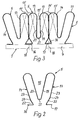
- the clamping finger pairs 5 comprise, as can be seen in particular from FIGS. 2 and 3, two clamping fingers 13 and 14 which initially, that is to say in the state not yet fastened to the carrier tape 4, delimit a V-shaped intermediate space 15 between them.
- the clamping finger pairs 5 are each made of one-piece flat strips, in particular made of spring steel, with a width of approx. 15 mm formed and have a front mounting tab 16 and a rear mounting tab 17, which run in the plane of the top of the magazine band or the carrier tape 4. If necessary, a surface coating or other treatment of the flat strip forming the clamping finger pairs 5 can be carried out, or the flat strip can consist of a suitable plastic overall.
- the pairs of clamping fingers 5 according to FIG. 2 are combined with the carrying band 4 in such a way that the fastening tabs 16, 17 of adjacent pairs of clamping fingers 5 together, with mutual overlap, on the top of the band 4, e.g. are attached by riveting, as illustrated in FIG. 3 at 18 in phantom.
- the pairs of clamping fingers 5 are fastened in such a manner that they adjoin one another on the carrying band or strap 4 in such a way that the clamping fingers 13 and 14 of adjacent pairs of clamping fingers 5 are held in a mutual support system.
- This support system of the clamping fingers 13 and 14 leads to their deformation from their original position, which is illustrated by dash-dotted lines in FIG.
- the free, upper ends of the clamping fingers 13 and 14 are convexly curved, and the base of the space 15 and 15 'between the clamping fingers 13 and 14 of each pair of clamping fingers 5 forms a concave arched groove 21.
- the fastening tabs 16 and 17, on the other hand, are bent at an acute angle from the clamping fingers 13, 14 without a significant radius and are connected to the outside 23 of the respective clamping fingers 13 and 14 via a retracted connecting part 22.
- the transition of the connecting part 22 into the outside 23-of the respective clamping finger 13, 14 is formed by a bending line 24 with an outward-pointing curvature which runs approximately in the plane of the fillet 21.
- FIG. 1 also shows slide rails 25 which extend on both sides of the clamping finger pairs 5 over the entire length of the conveying run of the magazine belts 1, 2 and are adjustably connected to the carriers 10 perpendicular to the usually horizontal conveying direction of the magazine belt 1 or 2 .
- the insertion depth of the workpieces to be conveyed can be precisely defined, as is illustrated in FIG. 1, for example, for a workpiece 26 which protrudes slightly with its two end regions beyond the two magazine belts 1 and 2 and with its underside on the Slide rails 25 is supported.
- 1.2 guide rails 27 are attached to the carriers 10 on both sides of each clamping band.
- the guide rails 27 are mounted transversely to the direction of rotation of the magazine band 1 or 2 in mutually perpendicular directions on the carriers 10. Given the assumed horizontal conveying direction of the magazine belts 1, 2, they can therefore be adjusted in height and parallel to the drive shaft 9 in order, if necessary, to provide an edge guide for each to form transporting workpieces. Due to the adjustment options, the guide rails 27 can each be adapted to differently shaped parts or end regions of such parts projecting outward beyond the magazine strips 1, 2. This is shown in FIG. 1, for example, for a molded part 28 which comprises multiple bends.
- FIG. 1 In addition to the workpieces 26, 28 and 29, some smaller workpieces 30, 31, 32 and 33 of the most varied shapes are illustrated in FIG. 1 as examples, which are only transported by the magazine belt 1 because of their small dimensions transversely to the conveying direction.
- the device With its magazine belts, the device can be used in many ways as an insertion aid, material buffer or as a feed and discharge device. In operation, it can be coupled to the machine in which the workpieces are processed or treated in such a way that the magazine belts 1, 2 convey the parts held in the clamping finger pairs 5 to a removal position 34 in time with the machine to be loaded, which at a horizontal conveying direction of the magazine belts 1, 2 can be at an angle of 35 ° to the horizontal, for example. In principle, however, the conveying direction of the magazine belts 1, 2 can also be any suitable direction deviating from the horizontal, in particular more or less inclined.
- the workpiece located in the removal position 34 is removed by means of an up and down and pivotable removal and positioning device 35 and brought into a position suitable for input into the processing or treatment machine, which is illustrated in FIG. 1 at 26 'for the workpiece 26 is.
- FIGS. 4 to 9 show in FIG. 4 a molded part 36 with multiple bends, which is pressed with a thin vertical part 37 between the fingers 13 and 14 lying against one another with pretension and two pairs of clamping fingers 5 immediately following one another on the magazine belt and by means of clamping engagement this is fixed.
- a workpiece 38 which comprises a barb 39, is pressed into the intermediate space 15 'between the two clamping fingers 13, 14 of a pair of clamping fingers 5 and fixed by clamping engagement therewith.
- FIG. 6 A similar application example is illustrated in FIG. 6 with reference to the Wen published 29, which comprises two hooks 30 at its lower end.
- the workpiece 29 is in turn held in the intermediate space 15 'of the two clamping fingers 13 and 14 of a pair of clamping fingers 5, the clamping engagement being carried out in each case in the lower and upper end region of the intermediate space 15'.
- FIG. 7 shows the workpiece 31, which is a hollow body with a lower edge flange.
- the workpiece 31 is slipped onto the clamping fingers 13 and 14 of two adjacent pairs of clamping fingers 5, which are placed against one another with prestress, and in this way connected to them by clamping engagement, the lower edge flange additionally engaging in the respective intermediate space 15 ′ and clamped on the respective clamping fingers 13 and 14 is.
- FIG. 8 illustrates an angle 40 which is pressed with one leg between the adjacent fingers 13 and 14 of two adjacent pairs of clamping fingers 5.
- the workpiece 30, which is a flange disc is inserted into the intermediate space 15 ′ between the clamping fingers 13 and 14 of a pair of clamping fingers 5, as in the case of FIGS. 5 and 6.
- the space 15 'of each pair of clamping fingers 5 automatically opens to a certain extent in the deflection regions of the carrying band 4, but the mutual resilient bias of the clamping fingers 13 and 14 of adjacent pairs of clamping fingers 5 is retained under all operating conditions, regardless of whether they are in the for the workpiece transport unused state are held in a mutual support system or they take up a workpiece part to be conveyed between them.
Landscapes
- Engineering & Computer Science (AREA)
- Mechanical Engineering (AREA)
- Chain Conveyers (AREA)
- Feeding Of Workpieces (AREA)
- Forging (AREA)
- Threshing Machine Elements (AREA)
- Electrical Discharge Machining, Electrochemical Machining, And Combined Machining (AREA)
- Belt Conveyors (AREA)
- Manipulator (AREA)
- Structure Of Belt Conveyors (AREA)
Priority Applications (1)
| Application Number | Priority Date | Filing Date | Title |
|---|---|---|---|
| AT85105678T ATE31179T1 (de) | 1984-05-10 | 1985-05-09 | Vorrichtung zum transport von werkstuecken. |
Applications Claiming Priority (2)
| Application Number | Priority Date | Filing Date | Title |
|---|---|---|---|
| DE3417315A DE3417315C1 (de) | 1984-05-10 | 1984-05-10 | Vorrichtung zum Foerdern und/oder Zwischenspeichern von Werkstuecken |
| DE3417315 | 1984-05-10 |
Publications (2)
| Publication Number | Publication Date |
|---|---|
| EP0163977A1 true EP0163977A1 (fr) | 1985-12-11 |
| EP0163977B1 EP0163977B1 (fr) | 1987-12-02 |
Family
ID=6235460
Family Applications (1)
| Application Number | Title | Priority Date | Filing Date |
|---|---|---|---|
| EP85105678A Expired EP0163977B1 (fr) | 1984-05-10 | 1985-05-09 | Dispositif de transport de pièces à usiner |
Country Status (3)
| Country | Link |
|---|---|
| EP (1) | EP0163977B1 (fr) |
| AT (1) | ATE31179T1 (fr) |
| DE (2) | DE3417315C1 (fr) |
Cited By (5)
| Publication number | Priority date | Publication date | Assignee | Title |
|---|---|---|---|---|
| EP0841643A1 (fr) * | 1996-11-06 | 1998-05-13 | NCR International, Inc. | Dispositif pour stocker provisoirement des billets de banque |
| ES2126467A1 (es) * | 1995-10-24 | 1999-03-16 | Zanini Auto Grup Sa | Procedimiento para el tratamiento de pintura de piezas de diversas formas geometricas en proceso continuo. |
| NL2004369C2 (nl) * | 2010-03-09 | 2011-09-13 | Valk Systemen Bvvd | Werkwijze voor het behandelen van slanke producten. |
| CN107552694A (zh) * | 2017-09-29 | 2018-01-09 | 中铁隆昌铁路器材有限公司 | 缩径棒料自动上料机及道钉头部压型生产系统 |
| CN111908027A (zh) * | 2020-01-16 | 2020-11-10 | 吕国良 | 一种防止运动偏移的工件传送控制方法 |
Families Citing this family (2)
| Publication number | Priority date | Publication date | Assignee | Title |
|---|---|---|---|---|
| DE4406328A1 (de) * | 1994-02-28 | 1995-08-31 | Mueller Thomas | Vorrichtung zum Transport flächiger Werkstücke |
| DE102005059695A1 (de) * | 2005-12-14 | 2007-06-28 | Max Schlatterer Gmbh & Co Kg | Führungsband für eine Fördereinrichtung |
Citations (2)
| Publication number | Priority date | Publication date | Assignee | Title |
|---|---|---|---|---|
| US907790A (en) * | 1907-10-28 | 1908-12-29 | Bert L Hancock | Conveying-belt. |
| US2554935A (en) * | 1948-02-04 | 1951-05-29 | Cie De Pont A Mousson | Endless chain for conveying tubes and other parts |
Family Cites Families (4)
| Publication number | Priority date | Publication date | Assignee | Title |
|---|---|---|---|---|
| DE445365C (de) * | 1925-10-24 | 1927-06-03 | Fritz Werner Akt Ges | Foerdervorrichtung fuer Maschinen zur Bearbeitung von Massenteilen |
| US3376968A (en) * | 1965-03-26 | 1968-04-09 | George T. Lott | Loading fixture |
| US3703954A (en) * | 1971-03-16 | 1972-11-28 | Artos Engineering Co | Conveyor system for wire like articles |
| DE2944510A1 (de) * | 1979-11-03 | 1981-05-14 | O. & K. Geißler GmbH, 8000 München | Eingabemaschine fuer leiterplatten |
-
1984
- 1984-05-10 DE DE3417315A patent/DE3417315C1/de not_active Expired
-
1985
- 1985-05-09 DE DE8585105678T patent/DE3561105D1/de not_active Expired
- 1985-05-09 AT AT85105678T patent/ATE31179T1/de active
- 1985-05-09 EP EP85105678A patent/EP0163977B1/fr not_active Expired
Patent Citations (2)
| Publication number | Priority date | Publication date | Assignee | Title |
|---|---|---|---|---|
| US907790A (en) * | 1907-10-28 | 1908-12-29 | Bert L Hancock | Conveying-belt. |
| US2554935A (en) * | 1948-02-04 | 1951-05-29 | Cie De Pont A Mousson | Endless chain for conveying tubes and other parts |
Cited By (7)
| Publication number | Priority date | Publication date | Assignee | Title |
|---|---|---|---|---|
| ES2126467A1 (es) * | 1995-10-24 | 1999-03-16 | Zanini Auto Grup Sa | Procedimiento para el tratamiento de pintura de piezas de diversas formas geometricas en proceso continuo. |
| EP0841643A1 (fr) * | 1996-11-06 | 1998-05-13 | NCR International, Inc. | Dispositif pour stocker provisoirement des billets de banque |
| US6203000B1 (en) | 1996-11-06 | 2001-03-20 | Ncr Corporation | Escrow storage device |
| NL2004369C2 (nl) * | 2010-03-09 | 2011-09-13 | Valk Systemen Bvvd | Werkwijze voor het behandelen van slanke producten. |
| CN107552694A (zh) * | 2017-09-29 | 2018-01-09 | 中铁隆昌铁路器材有限公司 | 缩径棒料自动上料机及道钉头部压型生产系统 |
| CN111908027A (zh) * | 2020-01-16 | 2020-11-10 | 吕国良 | 一种防止运动偏移的工件传送控制方法 |
| CN111908027B (zh) * | 2020-01-16 | 2021-11-02 | 山东欣怡翔精密机械制造有限公司 | 一种防止运动偏移的工件传送控制方法 |
Also Published As
| Publication number | Publication date |
|---|---|
| ATE31179T1 (de) | 1987-12-15 |
| DE3561105D1 (en) | 1988-01-14 |
| EP0163977B1 (fr) | 1987-12-02 |
| DE3417315C1 (de) | 1986-01-02 |
Similar Documents
| Publication | Publication Date | Title |
|---|---|---|
| DE3606058C2 (de) | Schweißanlage für Kraftfahrzeugkarosserien | |
| AT394019B (de) | Foerdereinrichtung | |
| CH668734A5 (de) | Transporteinrichtung fuer eine fertigungsstrasse mit parallelgeschalteten bearbeitungsstationen. | |
| DE1173387B (de) | Taschenband zum Foerdern von Gegenstaenden durch eine Maschine | |
| DE19711129A1 (de) | Drehbare Pendelfördereinheit | |
| EP0965413B1 (fr) | Installation pour l'exécution d'une série d'opérations de montage et/ou de travail de pièces, en particulier de petites pièces | |
| DE2531133C3 (de) | Transfermaschine zum Bearbeiten, insbesondere Schleifen der beiden Seiten eines Brillenglases | |
| EP0873207B1 (fr) | Machine a usiner | |
| EP0163977B1 (fr) | Dispositif de transport de pièces à usiner | |
| DE3319220A1 (de) | Zufuehrvorrichtung fuer foerder- und sortiergeraete | |
| EP3715009B1 (fr) | Procédé de fabrication de grillage formant armature | |
| DE3411452C2 (de) | Fördereinrichtung für Werkstückträger, insbesondere für eine Montagemaschine | |
| EP0450555A2 (fr) | Station d'assemblage | |
| DE4033124B4 (de) | Intermittierende Vorschubvorrichtung | |
| DE2365779B2 (de) | Vorrichtung zum Ausrichten von Dosen | |
| EP0143921B1 (fr) | Dispositif de transport | |
| DE2952768C2 (de) | Transfer-Maschine mit mehreren Arbeitsstationen zum Montieren und/oder Bearbeiten von Werkstücken | |
| DE3344795A1 (de) | Positioniereinrichtung fuer zu etikettierende packungen | |
| DE3135441C2 (de) | Werkstück-Fördervorrichtung für Werkzeugmaschinen | |
| EP3951039B1 (fr) | Dispositif d'alimentation pour machines à coudre destiné au chargement automatique d'une machine à coudre en pièce à coudre | |
| DE19931172C1 (de) | Vorrichtung zum Separieren von nebeneinander liegend geförderten, insbesondere aus Metall bestehenden Streifen | |
| DE2950422A1 (de) | Selbsttaetig ausrichtender halter fuer eine reissverschluss-kuppelgliederreihe | |
| AT408966B (de) | Vorrichtung zum be- und entladen einer bearbeitungsstation für werkstücke, insbesondere für lagerschalen | |
| DE7138120U (de) | Vorrichtung zum Transport von Werkstücken und in losen Werkstückaufnahmen eingelegten Werkstücken von einer Beladesteiie zu Bearbeitungsplätzen bzw. Mascninen und von diesen zu einer Entladestelle | |
| EP0885100A1 (fr) | Dispositif de chargement pour presse a plateau |
Legal Events
| Date | Code | Title | Description |
|---|---|---|---|
| PUAI | Public reference made under article 153(3) epc to a published international application that has entered the european phase |
Free format text: ORIGINAL CODE: 0009012 |
|
| AK | Designated contracting states |
Designated state(s): AT BE CH DE FR GB IT LI NL SE |
|
| 17P | Request for examination filed |
Effective date: 19860606 |
|
| 17Q | First examination report despatched |
Effective date: 19870128 |
|
| GRAA | (expected) grant |
Free format text: ORIGINAL CODE: 0009210 |
|
| RAP1 | Party data changed (applicant data changed or rights of an application transferred) |
Owner name: MAROLD, JOSEF A. Owner name: SCHOENING, ROLF |
|
| RIN1 | Information on inventor provided before grant (corrected) |
Inventor name: SCHOENING, ROLF |
|
| AK | Designated contracting states |
Kind code of ref document: B1 Designated state(s): AT BE CH DE FR GB IT LI NL SE |
|
| RAP1 | Party data changed (applicant data changed or rights of an application transferred) |
Owner name: MAROLD, JOSEF A. Owner name: SCHOENING, ROLF |
|
| REF | Corresponds to: |
Ref document number: 31179 Country of ref document: AT Date of ref document: 19871215 Kind code of ref document: T |
|
| ITF | It: translation for a ep patent filed | ||
| REF | Corresponds to: |
Ref document number: 3561105 Country of ref document: DE Date of ref document: 19880114 |
|
| ET | Fr: translation filed | ||
| GBT | Gb: translation of ep patent filed (gb section 77(6)(a)/1977) | ||
| PLBE | No opposition filed within time limit |
Free format text: ORIGINAL CODE: 0009261 |
|
| STAA | Information on the status of an ep patent application or granted ep patent |
Free format text: STATUS: NO OPPOSITION FILED WITHIN TIME LIMIT |
|
| 26N | No opposition filed | ||
| PGFP | Annual fee paid to national office [announced via postgrant information from national office to epo] |
Ref country code: GB Payment date: 19900509 Year of fee payment: 6 |
|
| PGFP | Annual fee paid to national office [announced via postgrant information from national office to epo] |
Ref country code: CH Payment date: 19900528 Year of fee payment: 6 |
|
| ITTA | It: last paid annual fee | ||
| PGFP | Annual fee paid to national office [announced via postgrant information from national office to epo] |
Ref country code: SE Payment date: 19900531 Year of fee payment: 6 Ref country code: NL Payment date: 19900531 Year of fee payment: 6 Ref country code: AT Payment date: 19900531 Year of fee payment: 6 |
|
| PGFP | Annual fee paid to national office [announced via postgrant information from national office to epo] |
Ref country code: BE Payment date: 19900613 Year of fee payment: 6 |
|
| PG25 | Lapsed in a contracting state [announced via postgrant information from national office to epo] |
Ref country code: GB Effective date: 19910509 Ref country code: AT Effective date: 19910509 |
|
| PG25 | Lapsed in a contracting state [announced via postgrant information from national office to epo] |
Ref country code: SE Effective date: 19910510 |
|
| PGFP | Annual fee paid to national office [announced via postgrant information from national office to epo] |
Ref country code: DE Payment date: 19910529 Year of fee payment: 7 |
|
| PG25 | Lapsed in a contracting state [announced via postgrant information from national office to epo] |
Ref country code: LI Effective date: 19910531 Ref country code: CH Effective date: 19910531 Ref country code: BE Effective date: 19910531 |
|
| PGFP | Annual fee paid to national office [announced via postgrant information from national office to epo] |
Ref country code: FR Payment date: 19911128 Year of fee payment: 7 |
|
| BERE | Be: lapsed |
Owner name: MAROLD JOSEF A. Effective date: 19910531 Owner name: SCHONING ROLF Effective date: 19910531 |
|
| PG25 | Lapsed in a contracting state [announced via postgrant information from national office to epo] |
Ref country code: NL Effective date: 19911201 |
|
| GBPC | Gb: european patent ceased through non-payment of renewal fee | ||
| NLV4 | Nl: lapsed or anulled due to non-payment of the annual fee | ||
| REG | Reference to a national code |
Ref country code: CH Ref legal event code: PL |
|
| PG25 | Lapsed in a contracting state [announced via postgrant information from national office to epo] |
Ref country code: FR Effective date: 19930129 |
|
| PG25 | Lapsed in a contracting state [announced via postgrant information from national office to epo] |
Ref country code: DE Effective date: 19930202 |
|
| REG | Reference to a national code |
Ref country code: FR Ref legal event code: ST |
|
| EUG | Se: european patent has lapsed |
Ref document number: 85105678.8 Effective date: 19911209 |