EP0164025B1 - Oxygenator der Hohlfaser-Membranart und Verfahren zur Herstellung desselben - Google Patents
Oxygenator der Hohlfaser-Membranart und Verfahren zur Herstellung desselben Download PDFInfo
- Publication number
- EP0164025B1 EP0164025B1 EP85106296A EP85106296A EP0164025B1 EP 0164025 B1 EP0164025 B1 EP 0164025B1 EP 85106296 A EP85106296 A EP 85106296A EP 85106296 A EP85106296 A EP 85106296A EP 0164025 B1 EP0164025 B1 EP 0164025B1
- Authority
- EP
- European Patent Office
- Prior art keywords
- hollow fiber
- silicone
- oxygenator
- hollow
- silicone rubber
- Prior art date
- Legal status (The legal status is an assumption and is not a legal conclusion. Google has not performed a legal analysis and makes no representation as to the accuracy of the status listed.)
- Expired
Links
- 239000012510 hollow fiber Substances 0.000 title claims description 160
- 239000012528 membrane Substances 0.000 title claims description 117
- 238000004519 manufacturing process Methods 0.000 title claims description 19
- 238000000034 method Methods 0.000 title claims description 18
- 229920001296 polysiloxane Polymers 0.000 claims description 143
- 150000001875 compounds Chemical class 0.000 claims description 98
- 239000012530 fluid Substances 0.000 claims description 88
- 239000007788 liquid Substances 0.000 claims description 55
- 229920002379 silicone rubber Polymers 0.000 claims description 54
- 239000004945 silicone rubber Substances 0.000 claims description 50
- 239000000835 fiber Substances 0.000 claims description 44
- 239000000758 substrate Substances 0.000 claims description 41
- 239000000203 mixture Substances 0.000 claims description 37
- 229920002545 silicone oil Polymers 0.000 claims description 35
- 238000004140 cleaning Methods 0.000 claims description 31
- 239000002904 solvent Substances 0.000 claims description 26
- QVGXLLKOCUKJST-UHFFFAOYSA-N atomic oxygen Chemical compound [O] QVGXLLKOCUKJST-UHFFFAOYSA-N 0.000 claims description 25
- 239000007789 gas Substances 0.000 claims description 25
- 239000001301 oxygen Substances 0.000 claims description 25
- 229910052760 oxygen Inorganic materials 0.000 claims description 25
- -1 vinylmethylsiloxane units Chemical group 0.000 claims description 24
- LYCAIKOWRPUZTN-UHFFFAOYSA-N Ethylene glycol Chemical compound OCCO LYCAIKOWRPUZTN-UHFFFAOYSA-N 0.000 claims description 17
- 238000005192 partition Methods 0.000 claims description 17
- 238000004891 communication Methods 0.000 claims description 16
- MTHSVFCYNBDYFN-UHFFFAOYSA-N diethylene glycol Chemical compound OCCOCCO MTHSVFCYNBDYFN-UHFFFAOYSA-N 0.000 claims description 12
- XLYOFNOQVPJJNP-UHFFFAOYSA-N water Substances O XLYOFNOQVPJJNP-UHFFFAOYSA-N 0.000 claims description 11
- KFZMGEQAYNKOFK-UHFFFAOYSA-N Isopropanol Chemical compound CC(C)O KFZMGEQAYNKOFK-UHFFFAOYSA-N 0.000 claims description 9
- 229920001843 polymethylhydrosiloxane Chemical group 0.000 claims description 9
- 230000004907 flux Effects 0.000 claims description 8
- 229920000642 polymer Polymers 0.000 claims description 7
- 239000011148 porous material Substances 0.000 claims description 7
- LFQSCWFLJHTTHZ-UHFFFAOYSA-N Ethanol Chemical compound CCO LFQSCWFLJHTTHZ-UHFFFAOYSA-N 0.000 claims description 6
- PEDCQBHIVMGVHV-UHFFFAOYSA-N Glycerine Chemical compound OCC(O)CO PEDCQBHIVMGVHV-UHFFFAOYSA-N 0.000 claims description 6
- 238000010926 purge Methods 0.000 claims description 5
- 238000005470 impregnation Methods 0.000 claims description 4
- 229920003216 poly(methylphenylsiloxane) Polymers 0.000 claims description 4
- 235000011187 glycerol Nutrition 0.000 claims description 3
- 230000005484 gravity Effects 0.000 claims description 3
- 125000000118 dimethyl group Chemical group [H]C([H])([H])* 0.000 claims description 2
- CURLTUGMZLYLDI-UHFFFAOYSA-N Carbon dioxide Chemical compound O=C=O CURLTUGMZLYLDI-UHFFFAOYSA-N 0.000 description 36
- 239000008280 blood Substances 0.000 description 31
- 210000004369 blood Anatomy 0.000 description 31
- 229910002092 carbon dioxide Inorganic materials 0.000 description 31
- YXFVVABEGXRONW-UHFFFAOYSA-N Toluene Chemical compound CC1=CC=CC=C1 YXFVVABEGXRONW-UHFFFAOYSA-N 0.000 description 30
- 239000001569 carbon dioxide Substances 0.000 description 17
- 230000004087 circulation Effects 0.000 description 16
- 230000017531 blood circulation Effects 0.000 description 14
- 238000010586 diagram Methods 0.000 description 11
- 239000003921 oil Substances 0.000 description 10
- 239000004743 Polypropylene Substances 0.000 description 9
- 230000001706 oxygenating effect Effects 0.000 description 8
- VYPSYNLAJGMNEJ-UHFFFAOYSA-N Silicium dioxide Chemical compound O=[Si]=O VYPSYNLAJGMNEJ-UHFFFAOYSA-N 0.000 description 7
- 229920001155 polypropylene Polymers 0.000 description 7
- 239000007787 solid Substances 0.000 description 7
- ZWEHNKRNPOVVGH-UHFFFAOYSA-N 2-Butanone Chemical compound CCC(C)=O ZWEHNKRNPOVVGH-UHFFFAOYSA-N 0.000 description 6
- YMWUJEATGCHHMB-UHFFFAOYSA-N Dichloromethane Chemical compound ClCCl YMWUJEATGCHHMB-UHFFFAOYSA-N 0.000 description 6
- SZXQTJUDPRGNJN-UHFFFAOYSA-N dipropylene glycol Chemical compound OCCCOCCCO SZXQTJUDPRGNJN-UHFFFAOYSA-N 0.000 description 5
- 238000004382 potting Methods 0.000 description 5
- 241000283690 Bos taurus Species 0.000 description 4
- 102000001554 Hemoglobins Human genes 0.000 description 4
- 108010054147 Hemoglobins Proteins 0.000 description 4
- HTTJABKRGRZYRN-UHFFFAOYSA-N Heparin Chemical compound OC1C(NC(=O)C)C(O)OC(COS(O)(=O)=O)C1OC1C(OS(O)(=O)=O)C(O)C(OC2C(C(OS(O)(=O)=O)C(OC3C(C(O)C(O)C(O3)C(O)=O)OS(O)(=O)=O)C(CO)O2)NS(O)(=O)=O)C(C(O)=O)O1 HTTJABKRGRZYRN-UHFFFAOYSA-N 0.000 description 4
- 239000003377 acid catalyst Substances 0.000 description 4
- 238000004132 cross linking Methods 0.000 description 4
- 229920001971 elastomer Polymers 0.000 description 4
- 229960002897 heparin Drugs 0.000 description 4
- 229920000669 heparin Polymers 0.000 description 4
- 230000007774 longterm Effects 0.000 description 4
- 230000008569 process Effects 0.000 description 4
- 229920002631 room-temperature vulcanizate silicone Polymers 0.000 description 4
- 239000005060 rubber Substances 0.000 description 4
- UHOVQNZJYSORNB-UHFFFAOYSA-N Benzene Chemical compound C1=CC=CC=C1 UHOVQNZJYSORNB-UHFFFAOYSA-N 0.000 description 3
- XEKOWRVHYACXOJ-UHFFFAOYSA-N Ethyl acetate Chemical compound CCOC(C)=O XEKOWRVHYACXOJ-UHFFFAOYSA-N 0.000 description 3
- DNIAPMSPPWPWGF-UHFFFAOYSA-N Propylene glycol Chemical compound CC(O)CO DNIAPMSPPWPWGF-UHFFFAOYSA-N 0.000 description 3
- 230000008901 benefit Effects 0.000 description 3
- VLKZOEOYAKHREP-UHFFFAOYSA-N n-Hexane Chemical compound CCCCCC VLKZOEOYAKHREP-UHFFFAOYSA-N 0.000 description 3
- 230000035699 permeability Effects 0.000 description 3
- 239000000377 silicon dioxide Substances 0.000 description 3
- 239000004677 Nylon Substances 0.000 description 2
- 208000007536 Thrombosis Diseases 0.000 description 2
- 238000000576 coating method Methods 0.000 description 2
- 230000000052 comparative effect Effects 0.000 description 2
- 238000000151 deposition Methods 0.000 description 2
- 238000010438 heat treatment Methods 0.000 description 2
- 239000000463 material Substances 0.000 description 2
- 229910052751 metal Inorganic materials 0.000 description 2
- 229920001778 nylon Polymers 0.000 description 2
- 239000004814 polyurethane Substances 0.000 description 2
- 230000002265 prevention Effects 0.000 description 2
- 230000037452 priming Effects 0.000 description 2
- 230000001105 regulatory effect Effects 0.000 description 2
- ABJSOROVZZKJGI-OCYUSGCXSA-N (1r,2r,4r)-2-(4-bromophenyl)-n-[(4-chlorophenyl)-(2-fluoropyridin-4-yl)methyl]-4-morpholin-4-ylcyclohexane-1-carboxamide Chemical compound C1=NC(F)=CC(C(NC(=O)[C@H]2[C@@H](C[C@@H](CC2)N2CCOCC2)C=2C=CC(Br)=CC=2)C=2C=CC(Cl)=CC=2)=C1 ABJSOROVZZKJGI-OCYUSGCXSA-N 0.000 description 1
- BOSAWIQFTJIYIS-UHFFFAOYSA-N 1,1,1-trichloro-2,2,2-trifluoroethane Chemical compound FC(F)(F)C(Cl)(Cl)Cl BOSAWIQFTJIYIS-UHFFFAOYSA-N 0.000 description 1
- SCYULBFZEHDVBN-UHFFFAOYSA-N 1,1-Dichloroethane Chemical compound CC(Cl)Cl SCYULBFZEHDVBN-UHFFFAOYSA-N 0.000 description 1
- NPNPZTNLOVBDOC-UHFFFAOYSA-N 1,1-difluoroethane Chemical compound CC(F)F NPNPZTNLOVBDOC-UHFFFAOYSA-N 0.000 description 1
- 241001465754 Metazoa Species 0.000 description 1
- CTQNGGLPUBDAKN-UHFFFAOYSA-N O-Xylene Chemical compound CC1=CC=CC=C1C CTQNGGLPUBDAKN-UHFFFAOYSA-N 0.000 description 1
- 241000283973 Oryctolagus cuniculus Species 0.000 description 1
- 239000004698 Polyethylene Substances 0.000 description 1
- 239000002253 acid Substances 0.000 description 1
- 150000001298 alcohols Chemical class 0.000 description 1
- 230000004323 axial length Effects 0.000 description 1
- 230000015572 biosynthetic process Effects 0.000 description 1
- 238000005266 casting Methods 0.000 description 1
- 229920002301 cellulose acetate Polymers 0.000 description 1
- 238000009750 centrifugal casting Methods 0.000 description 1
- 239000003795 chemical substances by application Substances 0.000 description 1
- 239000011248 coating agent Substances 0.000 description 1
- 239000002131 composite material Substances 0.000 description 1
- 238000009833 condensation Methods 0.000 description 1
- 230000005494 condensation Effects 0.000 description 1
- 230000001276 controlling effect Effects 0.000 description 1
- 229920001577 copolymer Polymers 0.000 description 1
- 230000008021 deposition Effects 0.000 description 1
- KPUWHANPEXNPJT-UHFFFAOYSA-N disiloxane Chemical class [SiH3]O[SiH3] KPUWHANPEXNPJT-UHFFFAOYSA-N 0.000 description 1
- 238000001493 electron microscopy Methods 0.000 description 1
- 239000003822 epoxy resin Substances 0.000 description 1
- 230000002349 favourable effect Effects 0.000 description 1
- 238000005429 filling process Methods 0.000 description 1
- 239000010408 film Substances 0.000 description 1
- LNEPOXFFQSENCJ-UHFFFAOYSA-N haloperidol Chemical compound C1CC(O)(C=2C=CC(Cl)=CC=2)CCN1CCCC(=O)C1=CC=C(F)C=C1 LNEPOXFFQSENCJ-UHFFFAOYSA-N 0.000 description 1
- 239000001257 hydrogen Substances 0.000 description 1
- 229910052739 hydrogen Inorganic materials 0.000 description 1
- 125000004435 hydrogen atom Chemical class [H]* 0.000 description 1
- WGCNASOHLSPBMP-UHFFFAOYSA-N hydroxyacetaldehyde Natural products OCC=O WGCNASOHLSPBMP-UHFFFAOYSA-N 0.000 description 1
- 239000011344 liquid material Substances 0.000 description 1
- QSHDDOUJBYECFT-UHFFFAOYSA-N mercury Chemical compound [Hg] QSHDDOUJBYECFT-UHFFFAOYSA-N 0.000 description 1
- 229910052753 mercury Inorganic materials 0.000 description 1
- 239000002184 metal Substances 0.000 description 1
- 229910044991 metal oxide Inorganic materials 0.000 description 1
- 238000002156 mixing Methods 0.000 description 1
- 239000000178 monomer Substances 0.000 description 1
- 238000006213 oxygenation reaction Methods 0.000 description 1
- 238000012856 packing Methods 0.000 description 1
- 230000000149 penetrating effect Effects 0.000 description 1
- 229920002492 poly(sulfone) Polymers 0.000 description 1
- 229920002239 polyacrylonitrile Polymers 0.000 description 1
- 229920001707 polybutylene terephthalate Polymers 0.000 description 1
- 229920000515 polycarbonate Polymers 0.000 description 1
- 239000004417 polycarbonate Substances 0.000 description 1
- 229920000647 polyepoxide Polymers 0.000 description 1
- 229920000573 polyethylene Polymers 0.000 description 1
- 229920000139 polyethylene terephthalate Polymers 0.000 description 1
- 239000005020 polyethylene terephthalate Substances 0.000 description 1
- 229920000098 polyolefin Polymers 0.000 description 1
- 239000004810 polytetrafluoroethylene Substances 0.000 description 1
- 229920001343 polytetrafluoroethylene Polymers 0.000 description 1
- 229920002635 polyurethane Polymers 0.000 description 1
- 229920005749 polyurethane resin Polymers 0.000 description 1
- 230000009467 reduction Effects 0.000 description 1
- 229920005989 resin Polymers 0.000 description 1
- 239000011347 resin Substances 0.000 description 1
- 230000000717 retained effect Effects 0.000 description 1
- 238000000926 separation method Methods 0.000 description 1
- 229920002050 silicone resin Polymers 0.000 description 1
- 238000005549 size reduction Methods 0.000 description 1
- 238000001356 surgical procedure Methods 0.000 description 1
- 239000010409 thin film Substances 0.000 description 1
- 125000000391 vinyl group Chemical group [H]C([*])=C([H])[H] 0.000 description 1
- 239000008096 xylene Substances 0.000 description 1
Images






Classifications
-
- B—PERFORMING OPERATIONS; TRANSPORTING
- B01—PHYSICAL OR CHEMICAL PROCESSES OR APPARATUS IN GENERAL
- B01D—SEPARATION
- B01D61/00—Processes of separation using semi-permeable membranes, e.g. dialysis, osmosis or ultrafiltration; Apparatus, accessories or auxiliary operations specially adapted therefor
- B01D61/38—Liquid-membrane separation
-
- B—PERFORMING OPERATIONS; TRANSPORTING
- B01—PHYSICAL OR CHEMICAL PROCESSES OR APPARATUS IN GENERAL
- B01D—SEPARATION
- B01D69/00—Semi-permeable membranes for separation processes or apparatus characterised by their form, structure or properties; Manufacturing processes specially adapted therefor
- B01D69/14—Dynamic membranes
- B01D69/141—Heterogeneous membranes, e.g. containing dispersed material; Mixed matrix membranes
-
- Y—GENERAL TAGGING OF NEW TECHNOLOGICAL DEVELOPMENTS; GENERAL TAGGING OF CROSS-SECTIONAL TECHNOLOGIES SPANNING OVER SEVERAL SECTIONS OF THE IPC; TECHNICAL SUBJECTS COVERED BY FORMER USPC CROSS-REFERENCE ART COLLECTIONS [XRACs] AND DIGESTS
- Y10—TECHNICAL SUBJECTS COVERED BY FORMER USPC
- Y10S—TECHNICAL SUBJECTS COVERED BY FORMER USPC CROSS-REFERENCE ART COLLECTIONS [XRACs] AND DIGESTS
- Y10S128/00—Surgery
- Y10S128/03—Heart-lung
-
- Y—GENERAL TAGGING OF NEW TECHNOLOGICAL DEVELOPMENTS; GENERAL TAGGING OF CROSS-SECTIONAL TECHNOLOGIES SPANNING OVER SEVERAL SECTIONS OF THE IPC; TECHNICAL SUBJECTS COVERED BY FORMER USPC CROSS-REFERENCE ART COLLECTIONS [XRACs] AND DIGESTS
- Y10—TECHNICAL SUBJECTS COVERED BY FORMER USPC
- Y10S—TECHNICAL SUBJECTS COVERED BY FORMER USPC CROSS-REFERENCE ART COLLECTIONS [XRACs] AND DIGESTS
- Y10S261/00—Gas and liquid contact apparatus
- Y10S261/28—Blood oxygenators
Definitions
- This invention relates to a hollow fiber membrane type oxygenator according to the first part of Claim 1 and a method for manufacturing the same.
- An oxygenator of this type is known from EP-A-48 943.
- oxygenators include hollow fiber membrane type oxygenators which may be subdivided into two classes depending on the type of hollow fiber membrane, that is, homogeneous membranes and porous membranes.
- the homogeneous membranes cannot be as thin as 100 pm or less because of membrane strength since they are formed from silicone compound.
- the limited thickness in turn imposes a limitation on the permeation of gases, particularly carbon dioxide gas.
- a bundle of several ten thousand fibers to be assembled in an oxygenator becomes undesirably larger in size so that a greater volume of priming liquid is required. Additional problems are troublesome manufacture and an increased expense.
- Microporous membranes allow gases to pass therethrough as a volume flow because the micropores are substantially greater in size than the molecule of passing gases.
- a variety of oxygenators have been proposed using microporous membranes, for example, microporous polypropylene membranes.
- the microporous membranes have high permeability to water vapor-so that the performance becomes low due to water condensation and plasma can leak out of the membranes after a long term of blood circulation therethrough.
- Japanese Patent Publication No. 54-17052 proposes a hollow fiber membrane comprising a hollow fiber substrate having micropores of 10 micrometers or less in diameter extending throughout the side wall wherein a gas-unpermeable thin film of methylhydrogenpolysiloxane is formed on the side wall.
- a gas-unpermeable thin film of methylhydrogenpolysiloxane is formed on the side wall.
- the methylhydrogenpolysiloxane film is formed not only in the micropores, but also on the inner and outer surfaces of the hollow fiber substrates, the cavity of the hollow fiber substrates has a correspondingly reduced inner diameter, resulting in deteriorated gas exchangeability.
- the amount or thickness of methylhydrogenpolysiloxane filled in micropores is correspondingly increased so that the membrane as a whole exhibits reduced percentage permeabilities to gases such as oxygen and carbon dioxide.
- the polysiloxane-coated membranes have the problem that plasma leakage occurs after a long term operation as an oxygenator although they can be sufficiently employed in aqualungs or similar equipment.
- an improved oxygenator using hollow fiber-silicone composite membranes comprising hollow fibers having micropores filled with a silicone oil without forming a silicone oil layer on the side wall.
- This oxygenator is manufactured by prefabricating an oxygenator module having untreated hollow fibers incorporated, impregnating the hollow fibers with a silicone oil solution, removing the solution, and then passing a mixture of a solvent and a non-solvent for the silicone oil to thereby remove silicone oil deposits on the hollow fiber substrate side wall, thereby filling only the micropores with the silicone oil.
- the silicone oil-filled membranes are improved in plasma leakage, but have the possibility that the silicone oil will flow into the contacting blood.
- an object of the present invention to provide an improved hollow fiber membrane type oxygenator which has eliminated the above-mentioned drawbacks, prevents plasma leakage even after a long term of extracorporeal circulation and provides improved carbon dioxide removal and improved blood compatibility as well as compactness.
- Another object of the present invention is to provide a method for manufacturing such an improved hollow fiber membrane type oxygenator.
- a first aspect of the present invention is directed to a hollow fiber membrane type oxygenator comprising
- the micropores are filled with a silicone compound comprising a silicone rubber or a blend thereof with a silicone oil, but the hollow fiber membrane is substantially free of a layer of said silicone compound on its side wall.
- each hollow fiber membrane comprises a hollow porous fiber substrate having an inner diameter of 100 to 1,000 pm, a wall thickness of 5 to 200 pm, an average pore diameter of 0.01 to 5 urn, and a porosity of 20 to 80%, and
- the weight SW of the silicone compound filled in the fiber membrane micropores is within the following range: with the proviso that the hollow fiber has an outer diameter Do, an inner diameter D" a length L, and a porosity P, and the silicone compound has a specific gravity d.
- a fourth aspect of the present invention is directed to a method for manufacturing a hollow fiber membrane type oxygenator.
- the oxygenator is manufactured by the steps of
- a method for manufacturing a hollow fiber membrane type oxygenator comprising the steps of
- the filling liquid is selected from the group consisting of water, glycerine, ethylene glycol, diethylene glycol, aqueous ethanol, and aqueous isopropyl alcohol, and mixtures thereof.
- FIG. 1 there is schematically illustrated a hollow fiber membrane type oxygenator according to one embodiment of the present invention.
- the oxygenator generally designed at 10 includes a cylindrical housing 11 defining an interior space which receives therein a bundle 13 of a plurality of axially extending hollow fibers 12 each presenting a gas exchange membrane.
- the opposite ends of the hollow fibers 12 are fluid tightly retained by opposed partitions 14 and 15 which are fluid tightly engaged in the housing 11 at its opposite ends.
- the hollow fibers extend throughout the partition and preferably terminate at the outer surface of the partition.
- the partitions 14 and 15 and the corresponding housing ends are referred to as upper and lower partitions and upper and lower housing ends.
- Upper and lower conical headers 17 and 16 are fixedly secured to the opposite ends of the housing 11 by means of covers 18 threadably engaged on the housing ends, respectively.
- the inner surface of the lower header 16 and the outer surface of the lower partition 14 define a second fluid incoming chamber in the form of a blood incoming chamber 19 in fluid communication with the interior space of each hollow fiber 12.
- the header 16 has at its apex a second fluid inlet in the form of a blood inlet 20.
- the inner surface of the upper header 17 and the outer surface of the partition 15 defines a second fluid outgoing chamber in the form of a blood outgoing chamber 21 in fluid communication with the interior space of each hollow fiber 12.
- the header 17 has at its apex a second fluid outlet in the form of a blood outlet 22.
- the inner surfaces of the partitions 14, 15, the inner wall of the housing 11, and the outer wall of the hollow fibers 12 define a first fluid chamber in the form of a gas chamber 23.
- the housing 11 is provided near its upper and lower ends with a first fluid inlet in the form of a gas inlet 24 and a first fluid outlet in the form of a gas outlet 25 both in fluid communication with the gas chamber 23.
- the housing 11 at its intermediate inner wall portion is provided with a throttling/retaining throat 26 having a reduced diameter for throttling the bundle 13 or reducing the diameter of the bundle.
- a throat zone is formed in the fiber bundle 13 at an axially intermediate portion as shown in FIG. 1. Then, the packing density of fibers 12 in the bundle 13 varies in an axial direction and is maximum at an intermediate portion.
- the partitions 14 and 15 serve for the important function of isolating the interior from the exterior of the hollow fibers 12.
- the partitions 14 and 15 are formed by casting a highly polar, high molecular weight potting agent, for example, polyurethane, silicone, and epoxy resins by the centrifugal casting process to the inner wall surface of the housing end portions where it is cured.
- a number of hollow fibers 12 longer than the axial length of the housing 11 are prepared, opposite open ends of the fibers are sealed with a viscous resin, and then the fibers are placed in the housing 11 in mutually juxtaposed relationship.
- the opposite ends of the fiber bundle are completely covered with caps.
- the housing 11 is rotated about its longitudinal axis while a polymeric potting compound is introduced to the opposite ends where it is cured.
- the caps are then removed and the edge portions of the fiber bundle bonded with the potting compound are severed with a sharp knife to expose freshly cut openings of the hollow fibers 12 at their opposite ehds.
- Each of the hollow fiber membranes used in the oxygenator are hollow fiber-type gas-exchange membranes.
- a porous hollow fiber substrate 33 has a plurality of micropores 31 penetrating through its side wall 32, the micropores 31 are filled or plugged with a silicone compound 35 comprising a silicone rubber or a mixture thereof with a silicone oil without substantially forming a silicone layer on a side wall surface 34 of the fiber substrate.
- the porous hollow fiber substrates used as the base of the hollow fiber membranes may be formed of polymeric materials, for example, polypropylene, polyethylene, polytetrafluoroethylene, polysulfone, polyacrylonitrile, polyethylene terephthalate, polybutylene terephthalate, polycarbonate, polyurethane, 6,6- nylon, 6-nylon, and cellulose acetate.
- polypropylene polyethylene, polytetrafluoroethylene, polysulfone, polyacrylonitrile, polyethylene terephthalate, polybutylene terephthalate, polycarbonate, polyurethane, 6,6- nylon, 6-nylon, and cellulose acetate.
- polyolefins are preferred and polypropylene is most preferred.
- the gas-exchange membranes prepared from these hollow fiber substrates may exert sufficient performance required for an oxygenator, they must meet certain limitations on membrane thickness and porosity.
- the quantity q of a gas permeated through a membrane having a thickness I and a surface area A is given by the following equation. wherein P is a coefficient of permeability to the gas, and p is a pressure drop across the membrane.
- the hollow fiber membranes used in the practice of the present invention have the otherwise gas-permeable micropores filled with a silicone compound so that the effective membrane area is very small as compared with ordinary porous membranes. To compensate for this reduced effective area, the membrane thickness must be reduced as understood from the above equation. For this reason, the hollow fiber membranes used in the present invention may have a wall thickness I in the range of 5 to 200 IJm, and preferably 10 to 50 IJ m.
- the hollow fibers may have an inner diameter of 100 to 1,000 ⁇ m, and preferably 100 to 300 ⁇ m, and a porosity of 20 to 80%, and preferably 40 to 80%.
- the micropores in the side wall has a diameter of 0.01 to 5 pm, and preferably 0.01 to 1 um.
- Inner diameters of less than 100 um increase pressure loss to cause damage to blood and such slender hollow fibers are probably clogged. Inner diameters of more than 1,000 pm will result in deteriorated performance, particularly deteriorated oxygenating ability and require an increased volume of priming fluid. With porosities of less than 20%, the effective membrane area is accordingly reduced to deteriorate gas exchange performance. The strength of the hollow fiber membrane substrate becomes low at porosities in excess of 80%.
- the average diameter of micropores may be calculated according to a well-known mercury filling process or electronmicroscopy. Pore diameters of less than 0.01 um are too small to uniformly introduce a silicone solution in pores. With pore diameters in excess of 5 pm, the cylindrical portions of the silicone compound filling in the pores are mechanically weak so that it can flow out into the surrounding fluid or blood.
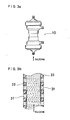
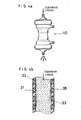
- the oxygenator according to the present invention may be manufactured by first incorporating a bundle of hollow fibers into an oxygenator module as shown in FIG. 3a, and passing a silicone solution, more specifically a solution of a silicone rubber or a silicone rubber-silicone oil mixture in a suitable solvent through the module to fully impregnate the fiber or membrane substrates 33 with the solution as shown in FIG. 3b. Then a gas is passed through the module to purge it of the silicone solution as shown in FIG. 4a and a cleaning liquid is then passed through at least the interior of the hollow fibers as shown in FIG. 4b, optionally followed by heating for crosslinking.
- a silicone solution more specifically a solution of a silicone rubber or a silicone rubber-silicone oil mixture in a suitable solvent
- a gas is passed through the module to purge it of the silicone solution as shown in FIG. 4a and a cleaning liquid is then passed through at least the interior of the hollow fibers as shown in FIG. 4b, optionally followed by heating for crosslinking.
- the silicone rubbers which can be used herein may be either one-part or two-part room temperature vulcanizable (RTV) silicone rubbers.
- Typical of the two-part RTV silicones are solid rubbers of planar polymer structure prepared by starting with a monomer or silicone oil containing vinyl group and/or hydrogen, and effecting crosslinking between C-H after mixing.
- Preferred examples of the two-part RTV silicone rubbers include copolymers of vinylmethylsiloxane and methylhydrogensiloxane.
- platinum group metals may be used in any form of metallic elements, oxides, and compounds, for example, chloroplatinic acid.
- the siloxane polymers may be cured at temperatures of about 20 to 30°C or higher.
- the silicone rubbers used herein are preferably silica-free RTV rubbers from a standpoint of thrombus prevention.
- the silicone compounds used herein may be silicone rubbers alone. Certain silicone rubbers, when used alone, have such a high viscosity even in solution state that they do not smoothly flow into the hollow fibers or membranes. It is thus preferred to use silicone rubbers in combination with silicone oils.
- the silicone oils used herein are liquid materials having siloxane bonds, for example, dimethylsilicone oil, methylphenylsilicone oil, methylchlorophenylsilicone oil, branched dimethylsilicone oil, methylhydro- gensilicone oil,-etc. Among these, dimethylsilicone oil and methylphenylsilicone oil are preferred, and dimethylsilicone oil is most preferred.
- the silicone blends used herein may contain silicone rubber (solid component) and silicone oil (liquid component) in a weight ratio between 2:8 and 8:2, and more preferably about 4:6. Provided that the blend . totals to 10 parts by weight, more than 8 parts of silicone rubber produces such a highly viscous solution that silicone deposits on the hollow fiber substrate wall surface are difficult to remove. Less than 2 parts of silicone rubber is insufficient to prevent the blended silicone oil from flowing out into the contacting blood.
- the silicone rubber or silicone blend are applied in the form of a solution of 20 to 80% by weight, and preferably 30 to 60% by weight.
- the solvent include benzene, toluene, xylene, hexane, dichloromethane, methyl ethyl ketone, difluoroethane, ethyl acetate, trifluorotrichloroethane (Freon, registered trademark), etc.
- the liquid or cleaning liquid for substantially removing the silicone rubber or silicone blend that has deposited on the hollow fiber substrate wall surface should be a non-solvent for the silicone, for example, alcohols because the once impregnated silicone is otherwise dissolved out.
- the cleaning liquids used may preferably have a viscosity of at least 10 centipoise, and particularly 30 to 80 centipoise at room temperature. Such cleaning liquids are effective in removing an excess of silicone rubber or silicone blend, ensuring the production of silicone-filled membranes having uniform quality and stable performance.
- the cleaning liquid may contain therein 10% by volume or less, particularly 0.5 to 10% by volume, and most preferably 2 to 6% by volume of the solvent for silicone as mentioned above while maintaining the viscosity in the above-defined range. Then an excessive silicone is readily removed to provide further improved performance. If more than 10% by volume of the solvent for silicone is present in the cleaning liquid, the necessary portion of the silicone filling can be dissolved out.
- cleaning liquid examples include blends of toluene and propylene glycol, toluene and dipropylene .glycol, dichloromethane and diethylene glycol, dichloroethane and ethylene glycol, methyl ethyl ketone and ethylene glycol, and the like.
- the substantial removal of the silicone compound as used herein means that the layer of silicone compound deposited on the inner wall of hollow fiber membranes is reduced to a thickness of 500 ⁇ or less.
- a silicone compound layer having a thickness of less than 500 ⁇ has little influence on the gas permeation through the membranes and ensures sufficient permeation of C0 2 as will be described hereinafter.
- all the micropores in the membrane need not be completely filled or plugged with the silicone compound. That is, substantial filling is satisfactory, which means that at least 90% of the micropores (in number) are filled with the silicone compound. Preferably, 95% of the micropores (in number) are filled with the silicone compound.
- the hollow fiber membrane type oxygenator of the present invention can be operated for an extended period of time with little plasma leakage and practically sufficient carbon dioxide removal capacity, it is desirable to strictly control the flow rate of oxygen permeating through the silicone fillings in micropores by regulating the concentration of the silicone compound solution with which the microporous hollow fiber membranes are impregnated.
- mmHg is represented by equation (1), it must meet equation (2) given below.
- Q is a volume of oxygen permeated expressed in ml/min.
- AP is a pressure drop across the membrane expressed in mmHg
- A is the surface area of the membrane expressed in m 2 .
- 0 2 Flux may be obtained by measuring the volume of oxygen permeated and the pressure drop in an actual oxygenator assembled from membranes and operating under conditions such that the flow rate of gas is 300 to 3,000 ml/min. per unit membrane area (1m 2 ). If O2 Flux is less than 1.0 ml/min. . m 2. mmHg, then carbon dioxide removal capacity is too low. Plasma leakage is considerably increased at O2 Flux of higher than 50 ml/min . m 2 . mmHg.
- the hollow fiber membranes in the oxygenator constructed according to the present invention can operate as gas-exchange membranes for an extended period of blood circulation with little plasma leakage and practically sufficient carbon dioxide removal capacity, it is desirable that the actual total weight SW expressed in gram of the silicone compound filling in micropores in the hollow fiber membranes and the various dimensions of the porous hollow fiber substrate meet the following equation: wherein
- the present invention allows a layer of the silicone compound as thin as 500 A or less to remain on the inner or outer wall of hollow fiber membranes.
- SW can be as great as about 120% of the theoretical total weight W (that is, SW ⁇ 1.2W), although it is less desirable.
- W the theoretical total weight
- better results are obtained when most micropores (in number) are partially (in volume) filled with the silicone compound so as to meet equation (3).
- the amount of the silicone compound filled may be controlled by regulating the concentration of the silicone compound solution, the proportion of the solvent for silicone in the cleaning liquid, and the like.
- the hollow fiber membranes are assembled in a module, impregnated with the silicone compound, that is, silicone rubber or silicone rubber-silicone oil blend, and then purged of the excessive silicone compound with a cleaning liquid in the form of a mixture of a solvent and a non-solvent for silicone.
- the silicone compound that is, silicone rubber or silicone rubber-silicone oil blend
- a cleaning liquid in the form of a mixture of a solvent and a non-solvent for silicone.
- the silicone compound penetrates out of the hollow fibers through micropores onto their outer wall to render the silicone fillings in micropores less uniform and hence, the membrane performance less stable.
- the following attention may preferably be paid in impregnating hollow fibers with a silicone compound solution.
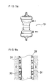
- either the first fluid chamber or the second fluid chamber is filled with a filling liquid A. Then, a silicone compound solution is introduced into the remaining fluid chamber which is not filled with filling liquid A.
- the first fluid chamber (23 in FIG. 1) is filled with filling liquid A as shown in FIGS. 5a and 5b.
- a silicone compound solution designated by arrow B is introduced into the second fluid chamber (19, 21 in FiG. 1) in communication with the interior space of the hollow fiber membrane substrates 33 as shown in FIGS. 6a and 6b. If a starting silicone compound solution is introduced into the first fluid chamber (23), that is, to the outside of the hollow fiber membranes, it becomes sometimes difficult to remove the silicone compound from the outer wall of the hollow fiber membranes.
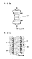
- the impregnating step will be further explained in conjunction with this embodiment wherein the first fluid chamber is filled with filling liquid A and silicone compound solution B is introduced into the second fluid chamber.
- the hollow fiber membrane substrates 33 are fully impregnated with a starting silicone compound solution B as shown in FIG. 6b, which is then discharged out of the module.
- cleaning liquid comprising a solvent and a non-solvent for silicone is introduced into the second fluid chamber as shown by arrow C in FIG. 7a and passed through at least the interior space of the hollow fibers or substrates 33 as shown in FIG. 7b. Thereafter, the module is purged or emptied of filling liquid A.
- a gas may be passed through the hollow fiber membrane substrates. Those excessive portions of the silicone compound which would clog in the hollow fiber membrane substrates and deposit on the inner wall thereof are more or less driven out to assist in increasing the efficiency of subsequent cleaning. Air may be used to this end.
- the oxygenator as a whole may be warmed up after introducing cleaning liquid and before emptying the first fluid chamber of the filling liquid, or a warm gas may be introduced into the interior space of the hollow fiber membrane substrates. This heating promotes crosslinking of the silicone compound so as to prevent the silicone compound from flowing onto the outside of the hollow fiber membrane substrates after emptying of the filling liquid.
- the filling liquid used herein has a higher surface tension than the critical surface tension of the hollow fiber membrane substrates 33.
- critical surface tension is a measure of the wettability of a solid mass on its surface.
- the solid is wettable with a liquid having a lower surface tension than the critical surface tension of the solid.
- Preferred examples of the filling liquid include water, glycerine, ethylene glycol, diethylene glycol, aqueous ethanol, aqueous isopropyl alcohol, etc. and mixtures thereof.
- the oxygenator of the invention has several benefits over prior art oxygenators using conventional porous hollow fiber membranes, including little plasma leakage in extended operation, high production efficiency, size reduction, cost reduction, and improved gas exchange efficiency due to the substantial absence of a silicone layer on the side wall of the hollow fiber membranes.
- a silicone compound used is a blend of a silicone rubber with a silicone oil
- the carbon dioxide removal capacity is noticeably improved over the use of a silicone rubber alone.
- the silicone rubber used is a silica-free room temperature vulcanizable silicone rubber, the resulting hollow fiber membranes are effective in preventing thrombus.
- porous hollow fibers having micropores open are bundled and assembled in a housing to produce an oxygenator module before they are impregnated with a silicone compound.
- a relatively simple apparatus may be used in the impregnating step, leading to a reduced manufacture cost.
- the present process provides an oxygenator without the problem of poor bond in the potting portions due to poor bondability of silicone.
- the impregnating and cleaning steps are conducted with the membrane exterior or interior filled with a predetermined filling liquid, the deposition of the silicone compound on the outer or inner wall of the hollow fiber membranes is minimized and the total weight of the silicone compound filled can be precisely controlled, both leading to stable performance.
- An oxygenator designated module A as shown in FIG. 1 was manufactured using hollow fibers of polypropylene which were formed by axially stretching to an inner diameter of 200 um and a wall thickness of 25 pm and had a plurality of micropores extending throughout the side wall and having an average diameter of 700 A and a porosity of 50%.
- a silicone compound solution was passed through the blood flow path in module A to impregnate the fibers with the solution for 3 minutes as shown in FIGS. 3a and 3b.
- the silicone compound solution used was a 60% Freon (registered trademark) solution of a silicone blend consisting of 40 wt% of a silica-free silicone rubber which was a two-part composition of vinylmethylsiloxane and methylhydrogensiloxane containing a chloroplatinic acid catalyst and 60 wt% of a dimethylsilicone oil.
- module A Thereafter, air was passed through the flow path in module A and a cleaning liquid was then passed along the inner and outer surfaces of the fibers.
- the cleaning liquid used was a 3% toluene/dipropylene glycol solution having a viscosity of 100 centipoise.
- module C There was obtained a hollow fiber membrane type oxygenator designated module C wherein only the micropores in the hollow fibers were substantially filled with the silicone compound.
- this oxygenator module C was evaluated by preparing venous blood having an oxygen saturation of 65% and a carbon dioxide partial pressure of 45 mmHg from fresh bovine blood having heparin added, and passing the blood through the module at 37°C.
- the blood contained 12 g hemoglobin per deciliter.
- the oxygenating and carbon dioxide (C0 2 ) removal capacities of the module were evaluated by operating the module at a predetermined flow rate of blood or oxygen.
- Curve C in FIG. 8 shows the oxygenating capacity as a function of the blood flow rate at an oxygen flow rate of 1000 ml/min/m 2 .
- Curve C in FIG. 9 shows the C0 2 removal capacity as a function of the oxygen flow rate at a blood flow rate of 1000 ml/min/m 2 .
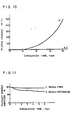
- the amount of plasma leaked is plotted as a function of circulation time to give curve C in FIG. 10.
- module B An oxygenator designated module B was manufactured which was similar to module A in Example 1 except that hollow fibers of silicone were used. Using this module B, tests were conducted by the same procedures as in Example 1. The results are similarly plotted in FIGS. 8, 9, and 10 as curves B.
- module A porous PP fiber membrane, curve A
- module B silicone fiber membrane, curve B
- module C silicone-filled PP fiber membrane, curve C
- the silicone membrane (module or curve B) was inferior as seen from FIG. 9.
- FIG. 10 based on a long term animal test shows that the amount of plasma leaked through the porous membrane (module or curve A) increased with time whereas no leakage of plasma occurred through the silicone-filled membrane (module or curve C) according to the present invention.
- An oxygenator designated module D of the same size as the module in Example 1 was manufactured by the same procedure as in Example 1 except that a silicone blend of a silica-containing silicone rubber (Si0 2 30 vol%) and a silicone oil was used as the silicone compound.
- Extracorporeal circulation tests were conducted through module D of this example and module C of Example 1 using rabbits.
- the number of platelets in circulating blood was measured at given time intervals.
- the percent variation of platelet number is plotted with time in FIG. 11 to give curves C and D corresponding to module C having hollow fibers treated with silica-free siicone and module D having hollow fibers treated with silica-containing silicone.
- FIG. 11 shows that silica-free silicone treated module C maintained the platelet number at 90% of the initial even after 6-hour operation whereas silica-containing silicone treated module D gradually reduced the platelet number to 70% of the initial after 6-hour operation.
- Oxygenators designated modules E to I as shown in FIG. 1 were manufactured using hollow fibers of polypropylene which were formed by axially stretching to an inner diameter of 200 pm and a wall thickness of 25 ⁇ m and had a plurality of micropores extending throughout the side wall and having an average diameter of 700 A and a porosity of 45%.
- the fibers had a total membrane area of 1.6 m 2 .
- a silicone compound solution was passed through the blood flow path in the module to impregnate the fibers with the solution for 3 minutes.
- the silicone compound solution used was a 60% Freon@ solution of a silicone blend consisting of a silicone rubber which was a two-part composition of vinylmethylsiloxane and methylhydrogensiloxane containing a chloroplatinic acid catalyst and a dimethylsilicone oil.
- modules E to I wherein only the micropores in the hollow fibers were substantially filled with the silicone compound.
- Modules E to I were the same except that the toluene/dipropylene glycol solutions used for cleaning had different toluene concentrations as shown in Table 1.
- the modules were operated with the volume of oxygen permeated set to 500 mi/min. and oxygen flow rate, 0 2 Flux, was measured. The results are shown in Table 1.
- the carbon dioxide (C0 2 ) removal capacity of the modules was evaluated by operating them at predetermined flow rates of blood and oxygen, that is, blood flow rate 1000 ml/min/m 2 and oxygen flow rate 3000 ml/min/m 2 . The results are shown in FIG. 12. Module E was practically insufficient in C0 2 removal.
- the amount of plasma leaked is plotted as a function of circulation time in FIG. 13. As seen from FIG. 13, a considerable volume of plasma leaked in module I. Plasma leaked in modules G and H, but to a physiologically neglectable extent. Curves G and H reached plateaus beyond which plasma leakage did not increase. No leakage of plasma occurred in modules E and F.
- Oxygenators designated modules J to M as shown in FIG. 1 was manufactured using the same hollow polypropylene fibers as in Example 3, that is, having an outer diameter D, of 250 ⁇ m, an inner diameter Do of 200 pm, a porosity P of 45%, and a length L of 13 cm.
- the fibers had a total membrane area of 1.6 m 2 .
- the fibers were impregnated with a silicone compound of a RTV silicone rubber and a silicone oil in solution form followed by curing. More illustratively, a silicone compound solution was passed through each prefabricated module to impregnate the fibers with the solution for 3 minutes.
- the silicone compound solution used was a Freon (registered trademark) solution of a silicone blend consisting of 40 wt% of a silicone rubber which was a two-part composition of vinylmethylsiloxane and methylhydrogensiloxane containing a chloroplatinic acid catalyst and 60 wt% of a dimethylsilicone oil. Thereafter, air was passed through the module and a 3% toluene/dipropylene glycol solution was then passed along the inner and outer surfaces of the fibers for cleaning. As a result, essentially only the micropores were filled with the silicone compound.
- the weight of the silicone compound filling in the micropores was controlled by varying the concentration of the silicone compound in the impregnating solution as shown in Table 2.
- the amount of silicone compound impregnated and SW/W are also shown in Table 2.
- Modules K and L met equation (3), that is, the actual silicone weight SW was controlled between 30% and 90% of the theoretical silicone weight W.
- module J had a SW equal to 0.2W and module M had a SW equal to 1.0.
- the CO 2 removal capacity of the modules was measured at a blood flow rate Q s of 1000 ml/min/m 2 and a V/Q of 3.0, with the results shown in FIG. 14.
- modules K and L are most preferred in plasma leakage.
- An oxygenator designated module N as shown in FIG. 1 was manufactured using hollow fibers of polypropylene which were formed by axially stretching to an inner diameter of 200 ⁇ m and a wall thickness of 25 um and had a plurality of micropores extending throughout the side wall and having an average diameter of 700 ⁇ and a porosity of 50%.
- the fibers had a membrane area of 1.0 m 2 .
- a silicone compound solution B was passed through the blood flow path in module N to impregnate the fibers with the solution for 3 minutes as shown in FIGS. 6a and 6b.
- the silicone compound solution used was a 60% Freon (registered trademark) solution of a silicone blend consisting of 40 wt% of a two-part silicone rubber of vinylmethylsiloxane and methylhydrogensiloxane containing a chloroplatinic acid catalyst and 60 wt% of a dimethylsilicone oil.
- module N Thereafter, air was passed through the flow path in module N and a cleaning liquid was then passed along the inner surface of the fibers as shown by arrow C in FIGS. 7a and 7b to thereby empty the module of the filling liquid or water.
- the cleaning liquid used was a 3% toluene/dipropylene glycol solution having a viscosity of 100 centipoise.
- module N There was obtained a hollow fiber membrane type oxygenator designated module N wherein only the micropores in the hollow fibers were substantially filled with the silicone compound.
- water had a surface tension of 72 dyn/cm and the outer surface of the hollow fiber membrane used had a critical surface tension of 30 dyn/cm.
- this oxygenator module N was evaluated by preparing venous blood having an oxygen saturation of 65% and a carbon dioxide partial pressure of 45 mmHg from fresh bovine blood having heparin added, and passing the blood through the module at 37°C.
- the blood contained 12 g hemoglobin per deciliter.
- the oxygenating and carbon dioxide (C0 2 ) removal capacities of the module were evaluated by operating the module at a predetermined flow rate of blood or oxygen.
- Curve N in FIG. 16 shows the oxygenating capacity as a function of the blood flow rate at an oxygen flow rate of 1000 ml/min/m 2 .
- Curve N in FIG. 17 shows the C0 2 removal capacity as a function of the oxygen flow rate at a blood flow rate of 1000 ml/min/m 2 .
- the amount of plasma leaked is plotted as a function of circulation time to give curve N in FIG. 18.
- module N having hollow fibers treated with silicone compound in the presence of water outside the fibers is further improved over module O having hollow fibers treated with the silicone compound in the absence of water outside the fibers. That is, module N provides the best performance.
Landscapes
- Chemical & Material Sciences (AREA)
- Chemical Kinetics & Catalysis (AREA)
- Dispersion Chemistry (AREA)
- Engineering & Computer Science (AREA)
- Water Supply & Treatment (AREA)
- External Artificial Organs (AREA)
Claims (20)


Applications Claiming Priority (8)
| Application Number | Priority Date | Filing Date | Title |
|---|---|---|---|
| JP10538484A JPS60249967A (ja) | 1984-05-24 | 1984-05-24 | 中空繊維膜型人工肺およびその製造方法 |
| JP105384/84 | 1984-05-24 | ||
| JP106278/84 | 1984-05-25 | ||
| JP106279/84 | 1984-05-25 | ||
| JP10627884A JPS60249968A (ja) | 1984-05-25 | 1984-05-25 | 中空繊維膜型人工肺 |
| JP10627984A JPS60249969A (ja) | 1984-05-25 | 1984-05-25 | 中空繊維膜型人工肺 |
| JP107179/84 | 1984-05-26 | ||
| JP10717984A JPS60249970A (ja) | 1984-05-26 | 1984-05-26 | 中空繊維膜型人工肺の製造方法 |
Publications (3)
| Publication Number | Publication Date |
|---|---|
| EP0164025A2 EP0164025A2 (de) | 1985-12-11 |
| EP0164025A3 EP0164025A3 (en) | 1986-09-17 |
| EP0164025B1 true EP0164025B1 (de) | 1989-02-01 |
Family
ID=27469320
Family Applications (1)
| Application Number | Title | Priority Date | Filing Date |
|---|---|---|---|
| EP85106296A Expired EP0164025B1 (de) | 1984-05-24 | 1985-05-22 | Oxygenator der Hohlfaser-Membranart und Verfahren zur Herstellung desselben |
Country Status (3)
| Country | Link |
|---|---|
| US (2) | US4923679A (de) |
| EP (1) | EP0164025B1 (de) |
| DE (1) | DE3568006D1 (de) |
Families Citing this family (44)
| Publication number | Priority date | Publication date | Assignee | Title |
|---|---|---|---|---|
| CA1280042C (en) * | 1985-09-13 | 1991-02-12 | Hiromichi Fukazawa | Membrane type artificial lung and method for manufacture thereof |
| CA1299033C (en) * | 1985-09-13 | 1992-04-21 | Hiromichi Fukazawa | Membrane type artificial lung and method for manufacture thereof |
| JPS63229061A (ja) * | 1987-03-18 | 1988-09-22 | テルモ株式会社 | 膜型人工肺とその製造方法 |
| AU611244B2 (en) * | 1987-12-25 | 1991-06-06 | Terumo Kabushiki Kaisha | Medical instrument |
| US5152743A (en) * | 1988-08-05 | 1992-10-06 | Healthdyne, Inc. | Apparatus and method for selective separation of blood cholesterol |
| US5116308A (en) * | 1989-01-13 | 1992-05-26 | Terumo Kabushiki Kaisha | Apparatus for processing fluid and method of driving the same |
| US5270004A (en) | 1989-10-01 | 1993-12-14 | Minntech Corporation | Cylindrical blood heater/oxygenator |
| US5186842A (en) * | 1991-07-15 | 1993-02-16 | Umpqua Research Company | Method for removing low molecular weight contaminants |
| JP3149970B2 (ja) * | 1991-08-06 | 2001-03-26 | ジャパンゴアテックス株式会社 | 散気材及びそれを用いたガスの散気方法 |
| US5234591A (en) * | 1991-12-04 | 1993-08-10 | Exxon Research & Engineering Company | Counter-current flow hollow fiber permeator |
| US5277176A (en) * | 1992-06-29 | 1994-01-11 | Habashi Nader M | Extracorporeal lung assistance apparatus and process |
| US5489413A (en) * | 1992-11-03 | 1996-02-06 | Cobe Laboratories, Inc. | Hollow fiber blood oxygenator |
| US5328610A (en) * | 1993-06-15 | 1994-07-12 | Integrated Process Technologies | Self-supported low pressure drop hollow fiber membrane panel and contactor module |
| US5814134A (en) * | 1994-06-10 | 1998-09-29 | Johnson & Johnson Vision Products, Inc. | Apparatus and method for degassing deionized water for inspection and packaging |
| EP0701826B1 (de) * | 1994-09-02 | 2000-03-22 | Terumo Kabushiki Kaisha | Dialysegerät |
| JP3130751B2 (ja) * | 1995-01-30 | 2001-01-31 | 株式会社荏原製作所 | オゾン水製造方法及び装置 |
| US5674394A (en) * | 1995-03-24 | 1997-10-07 | Johnson & Johnson Medical, Inc. | Single use system for preparation of autologous plasma |
| JPH0959517A (ja) * | 1995-06-12 | 1997-03-04 | Fuji Syst Kk | シリコーンゴム組成物並びに同組成物を使用した中空糸及び同中空糸の製造方法 |
| US6086769A (en) * | 1996-09-16 | 2000-07-11 | Commodore Separation Technologies, Inc. | Supported liquid membrane separation |
| EP1174175B1 (de) * | 1999-04-02 | 2008-02-20 | Mitsubishi Rayon Co., Ltd. | Vergussmasse für ein hohlfasermembranmodul, hohlfasermembranmodul und dessen verwendung |
| US6395226B1 (en) * | 1999-04-06 | 2002-05-28 | Medtronic, Inc. | Alkoxysilane/alkysilane copolymer coating of medical devices |
| US6209855B1 (en) * | 1999-05-10 | 2001-04-03 | Canzone Limited | Gas/liquid mixing apparatus and method |
| US6508983B1 (en) | 1999-07-19 | 2003-01-21 | Cobe Cardiovascular | Exchanger apparatus and method of manufacture |
| US6638479B1 (en) | 1999-10-11 | 2003-10-28 | Medtronic, Inc. | Variable packing density in hollow fiber device |
| DE60202405T2 (de) * | 2001-06-28 | 2005-12-22 | Terumo K.K. | Künstliches Herz-Lungenkreislaufsystem |
| US6949132B2 (en) * | 2003-11-05 | 2005-09-27 | Systel, Llc | Axial degassing transfer lines |
| US7713331B2 (en) * | 2003-11-05 | 2010-05-11 | Rheodyne, Llc | Axial transfer line degassing |
| US7399339B2 (en) * | 2005-06-15 | 2008-07-15 | Gas Technology Institute | Polyoxometalate material for gaseous stream purification at high temperature |
| EP2305332B1 (de) * | 2006-01-19 | 2018-08-08 | Terumo Kabushiki Kaisha | Oxygenator |
| ES2263394B1 (es) * | 2006-02-01 | 2007-11-16 | Sener, Ingenieria Y Sistemas, S.A. | Colector de seccion transversal variable y pared delgada para paneles de absorcion solar. |
| US20090032446A1 (en) | 2007-08-01 | 2009-02-05 | Triwatech, L.L.C. | Mobile station and methods for diagnosing and modeling site specific effluent treatment facility requirements |
| US8545754B2 (en) | 2009-04-23 | 2013-10-01 | Medtronic, Inc. | Radial design oxygenator with heat exchanger |
| CN102753251B (zh) * | 2009-12-17 | 2016-11-16 | 皇家飞利浦电子股份有限公司 | 利用等离子泵和膜的氧气分离方法和系统 |
| JP5543875B2 (ja) * | 2010-08-06 | 2014-07-09 | 旭化成メディカル株式会社 | 中空糸モジュール |
| US8741029B2 (en) * | 2011-06-30 | 2014-06-03 | United Technologies Corporation | Fuel deoxygenation using surface-modified porous membranes |
| WO2013039967A1 (en) | 2011-09-12 | 2013-03-21 | Idex Health & Science Llc | Supersaturated fluid degassing |
| WO2015153370A2 (en) | 2014-03-29 | 2015-10-08 | Labib Mohamed E | Blood processing cartridges and systems, and methods for extracorporeal blood therapies |
| US10426884B2 (en) | 2015-06-26 | 2019-10-01 | Novaflux Inc. | Cartridges and systems for outside-in flow in membrane-based therapies |
| US10477883B2 (en) | 2015-08-25 | 2019-11-19 | Cornelius, Inc. | Gas injection assemblies for batch beverages having spargers |
| US10785996B2 (en) | 2015-08-25 | 2020-09-29 | Cornelius, Inc. | Apparatuses, systems, and methods for inline injection of gases into liquids |
| EP3352888B8 (de) | 2015-09-24 | 2022-01-12 | Princeton Trade and Technology Inc. | Kartuschen für hohlfasermembranbasierte therapien |
| CN109070005A (zh) * | 2016-05-11 | 2018-12-21 | 三菱化学可菱水株式会社 | 中空纤维膜组件 |
| US12064543B2 (en) | 2018-07-03 | 2024-08-20 | The General Hospital Corporation | System and method for extracorporeal carbon monoxide removal with phototherapy |
| US11040314B2 (en) | 2019-01-08 | 2021-06-22 | Marmon Foodservice Technologies, Inc. | Apparatuses, systems, and methods for injecting gasses into beverages |
Family Cites Families (11)
| Publication number | Priority date | Publication date | Assignee | Title |
|---|---|---|---|---|
| US3520416A (en) * | 1968-02-12 | 1970-07-14 | Pall Corp | Liquid and gas-permeable microporous materials and process for making the same |
| US3969240A (en) * | 1975-02-03 | 1976-07-13 | The United States Of America As Represented By The Department Of Health, Education And Welfare | Polysiloxane membrane lung |
| FR2374933A1 (fr) * | 1976-12-24 | 1978-07-21 | Rhone Poulenc Ind | Appareil a fibres creuses, utilisable notamment comme rein artificiel, et procede pour sa fabrication |
| JPS5416896A (en) * | 1977-06-21 | 1979-02-07 | Asahi Medical Co | Blood dialyser |
| US4239729A (en) * | 1978-06-06 | 1980-12-16 | Terumo Corporation | Oxygenator |
| JPS5757555A (en) * | 1980-09-25 | 1982-04-06 | Terumo Corp | Hollow fiber type artificial lung |
| US4319996A (en) * | 1980-11-10 | 1982-03-16 | Gelman Sciences, Inc. | Filter with initially flat membrane and curved membrane support |
| DE3106188C2 (de) * | 1981-02-19 | 1983-11-03 | Fraunhofer-Gesellschaft zur Förderung der angewandten Forschung e.V., 8000 München | Oxygenator-Membran |
| DE3138107A1 (de) * | 1981-09-24 | 1983-04-07 | Dr. Eduard Fresenius, Chemisch-pharmazeutische Industrie KG, 6380 Bad Homburg | Verfahren zur entfernung von stoffen aus waessrigen loesungen sowie vorrichtung zur durchfuehrung des verfahrens |
| US4588407A (en) * | 1982-09-09 | 1986-05-13 | Terumo Kabushiki Kaisha | Artificial organ and method for manufacture thereof |
| JPS59218161A (ja) * | 1983-05-27 | 1984-12-08 | テルモ株式会社 | 中空繊維型人工肺およびその製造方法 |
-
1985
- 1985-05-22 DE DE8585106296T patent/DE3568006D1/de not_active Expired
- 1985-05-22 EP EP85106296A patent/EP0164025B1/de not_active Expired
-
1989
- 1989-07-25 US US07/386,032 patent/US4923679A/en not_active Expired - Fee Related
-
1990
- 1990-02-23 US US07/484,385 patent/US5037610A/en not_active Expired - Fee Related
Also Published As
| Publication number | Publication date |
|---|---|
| EP0164025A3 (en) | 1986-09-17 |
| US5037610A (en) | 1991-08-06 |
| US4923679A (en) | 1990-05-08 |
| DE3568006D1 (en) | 1989-03-09 |
| EP0164025A2 (de) | 1985-12-11 |
Similar Documents
| Publication | Publication Date | Title |
|---|---|---|
| US5037610A (en) | Method for manufacturing a hollow fiber membrane oxygenator | |
| US4971836A (en) | Method for manufacture of hollow fiber membrane type artificial lung | |
| CA1158510A (en) | Hollow fiber-type artificial lung having enclosed heat exchanger | |
| EP0005866B1 (de) | Oxygenator | |
| US4389363A (en) | Method of potting microporous hollow fiber bundles | |
| EP0121911B1 (de) | Hohlfaserfiltermedium und Verfahren zu dessen Herstellung | |
| EP0908191B1 (de) | Hohlfasermembran-Oxygenator | |
| US4909989A (en) | Gas-exchange membrane for an artificial lung | |
| EP0167162A2 (de) | Hohlfaseroxygenator | |
| EP0041692B2 (de) | Blut-Oxygeniergerät | |
| JP2888607B2 (ja) | 人工肺用複合膜、その製造方法およびそれを用いた複合膜型人工肺 | |
| JPS641149B2 (de) | ||
| JPH0321189B2 (de) | ||
| JPS60249968A (ja) | 中空繊維膜型人工肺 | |
| JPS60249967A (ja) | 中空繊維膜型人工肺およびその製造方法 | |
| JPS6241739B2 (de) | ||
| JPS6264374A (ja) | 膜型人工肺の製造方法 | |
| JPS60249969A (ja) | 中空繊維膜型人工肺 | |
| JP3048652B2 (ja) | 膜型人工肺の製造方法 | |
| JP3051510B2 (ja) | 体外循環回路装置 | |
| JPH0542207A (ja) | 多孔質中空糸膜、人工肺および体外循環回路 | |
| JPS6264373A (ja) | 膜型人工肺 | |
| JPS59108563A (ja) | 中空糸型人工肺 | |
| JPS60150757A (ja) | 中空糸膜型人工肺 | |
| CA1254467A (en) | Hollow fiber type oxygenator |
Legal Events
| Date | Code | Title | Description |
|---|---|---|---|
| PUAI | Public reference made under article 153(3) epc to a published international application that has entered the european phase |
Free format text: ORIGINAL CODE: 0009012 |
|
| 17P | Request for examination filed |
Effective date: 19850619 |
|
| AK | Designated contracting states |
Designated state(s): BE DE FR GB SE |
|
| PUAL | Search report despatched |
Free format text: ORIGINAL CODE: 0009013 |
|
| AK | Designated contracting states |
Kind code of ref document: A3 Designated state(s): BE DE FR GB SE |
|
| 17Q | First examination report despatched |
Effective date: 19880601 |
|
| GRAA | (expected) grant |
Free format text: ORIGINAL CODE: 0009210 |
|
| AK | Designated contracting states |
Kind code of ref document: B1 Designated state(s): BE DE FR GB SE |
|
| REF | Corresponds to: |
Ref document number: 3568006 Country of ref document: DE Date of ref document: 19890309 |
|
| ET | Fr: translation filed | ||
| PLBE | No opposition filed within time limit |
Free format text: ORIGINAL CODE: 0009261 |
|
| STAA | Information on the status of an ep patent application or granted ep patent |
Free format text: STATUS: NO OPPOSITION FILED WITHIN TIME LIMIT |
|
| 26N | No opposition filed | ||
| EAL | Se: european patent in force in sweden |
Ref document number: 85106296.8 |
|
| PGFP | Annual fee paid to national office [announced via postgrant information from national office to epo] |
Ref country code: FR Payment date: 19950510 Year of fee payment: 11 |
|
| PGFP | Annual fee paid to national office [announced via postgrant information from national office to epo] |
Ref country code: GB Payment date: 19950511 Year of fee payment: 11 |
|
| PGFP | Annual fee paid to national office [announced via postgrant information from national office to epo] |
Ref country code: SE Payment date: 19950517 Year of fee payment: 11 |
|
| PGFP | Annual fee paid to national office [announced via postgrant information from national office to epo] |
Ref country code: DE Payment date: 19950523 Year of fee payment: 11 |
|
| PGFP | Annual fee paid to national office [announced via postgrant information from national office to epo] |
Ref country code: BE Payment date: 19950712 Year of fee payment: 11 |
|
| PG25 | Lapsed in a contracting state [announced via postgrant information from national office to epo] |
Ref country code: GB Effective date: 19960522 |
|
| PG25 | Lapsed in a contracting state [announced via postgrant information from national office to epo] |
Ref country code: SE Effective date: 19960523 |
|
| PG25 | Lapsed in a contracting state [announced via postgrant information from national office to epo] |
Ref country code: BE Effective date: 19960531 |
|
| BERE | Be: lapsed |
Owner name: TERUMO CORP. Effective date: 19960531 |
|
| GBPC | Gb: european patent ceased through non-payment of renewal fee |
Effective date: 19960522 |
|
| PG25 | Lapsed in a contracting state [announced via postgrant information from national office to epo] |
Ref country code: FR Effective date: 19970131 |
|
| PG25 | Lapsed in a contracting state [announced via postgrant information from national office to epo] |
Ref country code: DE Effective date: 19970201 |
|
| EUG | Se: european patent has lapsed |
Ref document number: 85106296.8 |
|
| REG | Reference to a national code |
Ref country code: FR Ref legal event code: ST |