EP0164112A1 - Poignet pour robot industriel - Google Patents
Poignet pour robot industriel Download PDFInfo
- Publication number
- EP0164112A1 EP0164112A1 EP19850106977 EP85106977A EP0164112A1 EP 0164112 A1 EP0164112 A1 EP 0164112A1 EP 19850106977 EP19850106977 EP 19850106977 EP 85106977 A EP85106977 A EP 85106977A EP 0164112 A1 EP0164112 A1 EP 0164112A1
- Authority
- EP
- European Patent Office
- Prior art keywords
- unit
- component
- bevel gear
- screw
- housing
- Prior art date
- Legal status (The legal status is an assumption and is not a legal conclusion. Google has not performed a legal analysis and makes no representation as to the accuracy of the status listed.)
- Granted
Links
Images

Classifications
-
- B—PERFORMING OPERATIONS; TRANSPORTING
- B25—HAND TOOLS; PORTABLE POWER-DRIVEN TOOLS; MANIPULATORS
- B25J—MANIPULATORS; CHAMBERS PROVIDED WITH MANIPULATION DEVICES
- B25J9/00—Program-controlled manipulators
- B25J9/10—Program-controlled manipulators characterised by positioning means for manipulator elements
- B25J9/102—Gears specially adapted therefor, e.g. reduction gears
-
- B—PERFORMING OPERATIONS; TRANSPORTING
- B25—HAND TOOLS; PORTABLE POWER-DRIVEN TOOLS; MANIPULATORS
- B25J—MANIPULATORS; CHAMBERS PROVIDED WITH MANIPULATION DEVICES
- B25J17/00—Joints
- B25J17/02—Wrist joints
- B25J17/0258—Two-dimensional joints
Definitions
- the present invention relates to a wrist for industrial robots according to the preamble of claim 1.
- a known arrangement is that the drive wheel is designed as a fixed part of the second unit and that the entire second unit is axially adjustable.
- One disadvantage of this arrangement is that it changes the position of the second unit in relation to the drive device for this unit.
- Another arrangement consists in dividing the second unit into two parts which are provided with threads in such a way that they can be screwed into one another for axial adjustment of the part carrying the teeth. After adjustment, the parts are fixed in relation to each other by two screws. This type of adjustment is relatively time consuming.
- the invention has for its object to develop a wrist for industrial robots of the type mentioned, in which the gear play can be set quickly and reliably without one of the two units having to be moved in the axial direction relative to the drive device.
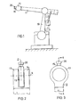
- the device shown in FIG. 1 has two adjustable arms 10, 11, the positions of which can be adjusted by means of electric motors which can be programmed in a known manner.
- a fixed housing 12 in which the invention characteristic parts of the wrist are housed.
- the housing is divided into two halves 13, 14, between which a housing 15 is arranged, which is rotatable about an axis X and has a sleeve-like shape, the longitudinal axis Z of which is oriented radially to the axis of rotation X.
- a first disk-shaped unit 16 (FIG. 4) carries the housing 15 and can be rotated about the transverse axis X, in the exemplary embodiment shown by a drive device which consists of two drive rods 17 and 18.
- a second disk-shaped unit 19 can also be rotated about the transverse axis X by a drive device which consists of two drive rods 20 and 20a.
- the two disk-shaped units are rotatably mounted in the wall 23 or 24 of the housing by means of ball bearings 21 or 22 and can be rotated independently of one another.
- a shaft 25 is arranged in the housing 15 so as to be rotatable about the Z axis running radially to the X axis. At its outer end, it is provided with a fastening device 26 for a tool holder or a similar working device.
- a driven bevel gear 27 is placed on the inner end of the shaft, the teeth 28 of which are in engagement with the teeth 29 of the driving bevel gear 30.
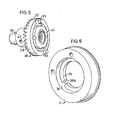
- the bevel gear 30 is a second component of the second disk-shaped unit 19, which also includes an annular first component 31.
- the bevel gear 30 has a cylindrical guide surface 32 and two claws 33 which protrude from the rear end surface in the axial direction.
- the first component 31 has a cylindrical recess 34 which receives the guide surface 32 of the bevel gear.
- Both components 30, 31 are connected to one another by the claws 33, which are displaceable in the axial direction in the recesses 35A, in such a way that a mutual rotation of the components is not possible.
- the first unit 16 is essentially in the form of a disk 36 which is fastened to the wall 38 of the housing 15 by means of screws 37.
- the inner ring 21A of the bearing 21 and a spacer ring 39 form a spacer and at the same time a force-transmitting member between the disk 36 and the housing 15, which together form the first unit 16.
- the bevel gear 30 is extended by a sleeve 40 to which the bevel gear is connected in a non-rotatable manner by means of a ring nut 41.
- bevel gear 30 and sleeve 40 may be made as an integral component.
- the end of the sleeve 40 facing away from the bevel gear is rotatable in the first unit by means of a needle bearing 42 16 stored. Precise centering of the bevel gear 30 is thereby achieved since the bevel gear with its teeth 29 is supported by two bearings 42 and 22 which are located at a relatively large distance from one another.
- an adjusting screw 43 is provided, which extends through a central hole in the first unit 16 extends and is guided through the bore in the sleeve 40.
- the screw 43 has a head 44 which is rotatably abutted against the first unit via an axial needle bearing 45.
- the screw head has a slot 46 so that the screw can be easily turned using a screwdriver or other tool.
- the screw 43 is normally held in relation to the sleeve 40 by a pair of locking screws 47 which are easily accessible by means of a screwdriver through an opening 48 in the wall 49 of the housing 15.
- the end portion of the screw 43 is provided with thread 50, which cooperates with a corresponding thread 51 on the inside of the sleeve 40.
- the adjusting screw 43 can be turned by means of a screwdriver.
- the bevel gear 30 with the sleeve 40 of the second unit are blocked against rotation by the second disc-shaped unit 19 and the connecting rods 20 ; 20a, while at the same time an axial displacement is imposed on the bevel gear 30 and the sleeve 40 via the threads 50, 51 until the desired play between the bevel gears has been achieved.
- the screws 47 are fixed again.
- a realignment of the axi The position of the bevel gear 30 can be carried out quickly and reliably even by less qualified personnel.
- a resilient sealing ring 52 which is under tension, is arranged between a nut 53 seated on the screw 43 and an intermediate ring 54, the intermediate ring 54 abutting against a shoulder 35 of the annular component 31.
- a ball bearing 55 is arranged between the housing 15 and the second unit 19 and, together with the bearing 22, forms the assembly on one side of the housing 15, while the housing is supported on the other side by the bearing 21.
Landscapes
- Engineering & Computer Science (AREA)
- Robotics (AREA)
- Mechanical Engineering (AREA)
- Manipulator (AREA)
Applications Claiming Priority (2)
| Application Number | Priority Date | Filing Date | Title |
|---|---|---|---|
| SE8403043 | 1984-06-06 | ||
| SE8403043A SE454251B (sv) | 1984-06-06 | 1984-06-06 | Robothandled med anordning for justering av kuggspel |
Publications (2)
| Publication Number | Publication Date |
|---|---|
| EP0164112A1 true EP0164112A1 (fr) | 1985-12-11 |
| EP0164112B1 EP0164112B1 (fr) | 1987-09-16 |
Family
ID=20356157
Family Applications (1)
| Application Number | Title | Priority Date | Filing Date |
|---|---|---|---|
| EP19850106977 Expired EP0164112B1 (fr) | 1984-06-06 | 1985-06-05 | Poignet pour robot industriel |
Country Status (3)
| Country | Link |
|---|---|
| EP (1) | EP0164112B1 (fr) |
| DE (1) | DE3560617D1 (fr) |
| SE (1) | SE454251B (fr) |
Cited By (6)
| Publication number | Priority date | Publication date | Assignee | Title |
|---|---|---|---|---|
| FR2610562A1 (fr) * | 1987-02-05 | 1988-08-12 | Euritech | Pince d'intervention articulee a cinq degres de liberte |
| EP0291864A1 (fr) * | 1987-05-20 | 1988-11-23 | Asea Brown Boveri Ab | Dispositif d'articulation pour relier deux parties d'un bras de robot |
| CN105276137A (zh) * | 2014-06-11 | 2016-01-27 | 桂林航天工业学院 | 二轴座式自重消隙数控变位机 |
| CN105945991A (zh) * | 2016-05-28 | 2016-09-21 | 东莞市联洲知识产权运营管理有限公司 | 一种执行末端可摆动的机器人 |
| CN110625107A (zh) * | 2019-11-05 | 2019-12-31 | 湖北华远装备制造股份有限公司 | 一种钢包长水口机械手 |
| EP3636391A1 (fr) * | 2018-10-11 | 2020-04-15 | BSH Hausgeräte GmbH | Articulation et assistant ménager |
Families Citing this family (1)
| Publication number | Priority date | Publication date | Assignee | Title |
|---|---|---|---|---|
| CN110328767B (zh) * | 2019-07-01 | 2021-07-23 | Tcl华星光电技术有限公司 | 一种残材夹取装置 |
Citations (3)
| Publication number | Priority date | Publication date | Assignee | Title |
|---|---|---|---|---|
| GB249340A (en) * | 1925-04-17 | 1926-03-25 | John Pierce | Improvements relating to bevel gearing |
| EP0089129A2 (fr) * | 1982-03-12 | 1983-09-21 | Fanuc Ltd. | Mécanisme de transmission de force avec régulateur de jeu pour robot industriel |
| SE435030B (sv) * | 1983-01-25 | 1984-09-03 | Asea Ab | Handled for robot |
-
1984
- 1984-06-06 SE SE8403043A patent/SE454251B/sv not_active IP Right Cessation
-
1985
- 1985-06-05 DE DE8585106977T patent/DE3560617D1/de not_active Expired
- 1985-06-05 EP EP19850106977 patent/EP0164112B1/fr not_active Expired
Patent Citations (3)
| Publication number | Priority date | Publication date | Assignee | Title |
|---|---|---|---|---|
| GB249340A (en) * | 1925-04-17 | 1926-03-25 | John Pierce | Improvements relating to bevel gearing |
| EP0089129A2 (fr) * | 1982-03-12 | 1983-09-21 | Fanuc Ltd. | Mécanisme de transmission de force avec régulateur de jeu pour robot industriel |
| SE435030B (sv) * | 1983-01-25 | 1984-09-03 | Asea Ab | Handled for robot |
Cited By (6)
| Publication number | Priority date | Publication date | Assignee | Title |
|---|---|---|---|---|
| FR2610562A1 (fr) * | 1987-02-05 | 1988-08-12 | Euritech | Pince d'intervention articulee a cinq degres de liberte |
| EP0291864A1 (fr) * | 1987-05-20 | 1988-11-23 | Asea Brown Boveri Ab | Dispositif d'articulation pour relier deux parties d'un bras de robot |
| CN105276137A (zh) * | 2014-06-11 | 2016-01-27 | 桂林航天工业学院 | 二轴座式自重消隙数控变位机 |
| CN105945991A (zh) * | 2016-05-28 | 2016-09-21 | 东莞市联洲知识产权运营管理有限公司 | 一种执行末端可摆动的机器人 |
| EP3636391A1 (fr) * | 2018-10-11 | 2020-04-15 | BSH Hausgeräte GmbH | Articulation et assistant ménager |
| CN110625107A (zh) * | 2019-11-05 | 2019-12-31 | 湖北华远装备制造股份有限公司 | 一种钢包长水口机械手 |
Also Published As
| Publication number | Publication date |
|---|---|
| SE8403043D0 (sv) | 1984-06-06 |
| SE454251B (sv) | 1988-04-18 |
| EP0164112B1 (fr) | 1987-09-16 |
| SE8403043L (sv) | 1985-12-07 |
| DE3560617D1 (en) | 1987-10-22 |
Similar Documents
| Publication | Publication Date | Title |
|---|---|---|
| DE3531160A1 (de) | Werkzeugwechsler fuer eine werkzeugmaschine | |
| CH656335A5 (de) | Bohrwerkzeug. | |
| DE3929802C1 (fr) | ||
| DE3613987C2 (fr) | ||
| DE3719064A1 (de) | Roboterhandgelenk | |
| EP0410104B1 (fr) | Outil d'usinage par enlèvement de copeaux | |
| EP0164112B1 (fr) | Poignet pour robot industriel | |
| DE3605913C2 (fr) | ||
| EP0684099A1 (fr) | Outil combiné | |
| DE2511081A1 (de) | Schlitz- oder stemm-maschine | |
| DE2726080C2 (de) | Anordnung zum Verschieben eines Wälzlagers in beiden axialen Richtungen | |
| DE3224294C2 (fr) | ||
| DE102017201404A1 (de) | Bearbeitungssystem | |
| CH688522A5 (de) | Einrichtung zur Befestigung einer Achse. | |
| EP0860227A1 (fr) | Fraise pour surfaces planes ou coins | |
| DE1491029A1 (de) | Zahnaertzliches Handstueck | |
| DE3814189C2 (fr) | ||
| DE3908586C2 (fr) | ||
| DE69301591T2 (de) | Befestigungs- und Schwenkeinrichtung für eine über einer Grundplatte befindlichen Vorrichtung | |
| DE3872767T2 (de) | Gelenkeinrichtung zum verbinden von zwei teilen eines roboterarmes. | |
| CH660992A5 (de) | Vorrichtung zur kuehlmittelzufuhr zu mit kuehlmittelkanaelen versehenen, rotierenden schneidwerkzeugen fuer die spanende metallbearbeitung, insbesondere bohrwerkzeuge. | |
| DE102020123783B4 (de) | Vorrichtung zum zerspanenden Bearbeiten | |
| EP0429074B1 (fr) | Tête de fraisage à finir des pièces, specialement pour des cylindres à impression en creux | |
| DE3432942C2 (fr) | ||
| DE69700335T2 (de) | Handwerkzeug zum Bearbeiten von Werkstücken, insbesondere Metallwerkstücken |
Legal Events
| Date | Code | Title | Description |
|---|---|---|---|
| PUAI | Public reference made under article 153(3) epc to a published international application that has entered the european phase |
Free format text: ORIGINAL CODE: 0009012 |
|
| AK | Designated contracting states |
Designated state(s): DE FR GB IT |
|
| 17P | Request for examination filed |
Effective date: 19860321 |
|
| 17Q | First examination report despatched |
Effective date: 19861106 |
|
| GRAA | (expected) grant |
Free format text: ORIGINAL CODE: 0009210 |
|
| AK | Designated contracting states |
Kind code of ref document: B1 Designated state(s): DE FR GB IT |
|
| REF | Corresponds to: |
Ref document number: 3560617 Country of ref document: DE Date of ref document: 19871022 |
|
| ITF | It: translation for a ep patent filed | ||
| ET | Fr: translation filed | ||
| PLBE | No opposition filed within time limit |
Free format text: ORIGINAL CODE: 0009261 |
|
| STAA | Information on the status of an ep patent application or granted ep patent |
Free format text: STATUS: NO OPPOSITION FILED WITHIN TIME LIMIT |
|
| 26N | No opposition filed | ||
| ITTA | It: last paid annual fee | ||
| PGFP | Annual fee paid to national office [announced via postgrant information from national office to epo] |
Ref country code: GB Payment date: 19990602 Year of fee payment: 15 |
|
| PGFP | Annual fee paid to national office [announced via postgrant information from national office to epo] |
Ref country code: DE Payment date: 19990607 Year of fee payment: 15 |
|
| PGFP | Annual fee paid to national office [announced via postgrant information from national office to epo] |
Ref country code: FR Payment date: 19990610 Year of fee payment: 15 |
|
| PG25 | Lapsed in a contracting state [announced via postgrant information from national office to epo] |
Ref country code: GB Free format text: LAPSE BECAUSE OF NON-PAYMENT OF DUE FEES Effective date: 20000605 |
|
| GBPC | Gb: european patent ceased through non-payment of renewal fee |
Effective date: 20000605 |
|
| PG25 | Lapsed in a contracting state [announced via postgrant information from national office to epo] |
Ref country code: FR Free format text: LAPSE BECAUSE OF NON-PAYMENT OF DUE FEES Effective date: 20010228 |
|
| REG | Reference to a national code |
Ref country code: FR Ref legal event code: ST |
|
| PG25 | Lapsed in a contracting state [announced via postgrant information from national office to epo] |
Ref country code: DE Free format text: LAPSE BECAUSE OF NON-PAYMENT OF DUE FEES Effective date: 20010403 |