EP0164191A1 - Absetz- und Aufnahmegerät - Google Patents
Absetz- und Aufnahmegerät Download PDFInfo
- Publication number
- EP0164191A1 EP0164191A1 EP85302467A EP85302467A EP0164191A1 EP 0164191 A1 EP0164191 A1 EP 0164191A1 EP 85302467 A EP85302467 A EP 85302467A EP 85302467 A EP85302467 A EP 85302467A EP 0164191 A1 EP0164191 A1 EP 0164191A1
- Authority
- EP
- European Patent Office
- Prior art keywords
- boom
- luffing
- weight
- stacker
- pivot
- Prior art date
- Legal status (The legal status is an assumption and is not a legal conclusion. Google has not performed a legal analysis and makes no representation as to the accuracy of the status listed.)
- Granted
Links
- 238000006073 displacement reaction Methods 0.000 claims abstract description 8
- 239000000463 material Substances 0.000 claims description 10
- 230000003028 elevating effect Effects 0.000 claims description 4
- 238000004260 weight control Methods 0.000 claims 1
- 238000010276 construction Methods 0.000 description 2
- 230000005484 gravity Effects 0.000 description 2
- 239000013590 bulk material Substances 0.000 description 1
- 230000006835 compression Effects 0.000 description 1
- 238000007906 compression Methods 0.000 description 1
- 230000007423 decrease Effects 0.000 description 1
- 238000000151 deposition Methods 0.000 description 1
- 238000012986 modification Methods 0.000 description 1
- 230000004048 modification Effects 0.000 description 1
Images

Classifications
-
- B—PERFORMING OPERATIONS; TRANSPORTING
- B65—CONVEYING; PACKING; STORING; HANDLING THIN OR FILAMENTARY MATERIAL
- B65G—TRANSPORT OR STORAGE DEVICES, e.g. CONVEYORS FOR LOADING OR TIPPING, SHOP CONVEYOR SYSTEMS OR PNEUMATIC TUBE CONVEYORS
- B65G65/00—Loading or unloading
- B65G65/02—Loading or unloading machines comprising essentially a conveyor for moving the loads associated with a device for picking-up the loads
- B65G65/16—Loading or unloading machines comprising essentially a conveyor for moving the loads associated with a device for picking-up the loads with rotary pick-up conveyors
- B65G65/20—Paddle wheels
Definitions
- This invention relates to stacker-reclaimers for depositing bulk material on a stockpile and reclaiming material from the pile.
- Stacker-reclaimers comprising a forward or main boom that forms part of a boom structure on a luffing and slewing mounting.
- a conveyor extending along the boom conveys material to be stacked to the front end of the boom to deposit it on a stockpile.
- a bucket-wheel or other material-gathering device is mounted at the front end of the boom and collects the material to deposit it on the conveyor, which is then running in the reverse direction.
- the boom structure has a shorter tail boom which extends in the opposite direction from the mounting and carries a counterbalance weight at its rear extremity. In this way, the overturning moment on the mounting of the boom structure is reduced and the mounting can be constructed in a simpler and more economical manner.
- the tail boom In order to accommodate an elevating conveyor that delivers the material to the inner end of the main boom, when the stacker-reclaimer is working in the stacking mode, the tail boom must be considerably higher than the main boom and as a result there are variations in the effectiveness of the counterbalance weight when the boom structure is luffed. This arises because, whereas the axis of the main boom extends to the mounting at more or less at the same level as the luffing pivot, so that any point on the boom is displaced vertically or nearly vertically during luffing, the higher position of the tail boom results in the counterbalance weight having a significant horizontal component of displacement in the same luffing movement.
- a stacker-reclaimer having a boom structure supported on a luffing and slewing mounting, said structure comprising a main forwardly extending boom with conveying means for the material along its length and with material retrieval means at its forward end, and a rearwardly extending tail boom with a counterbalance weight remote from the mounting, the tail boom being disposed at a higher position than the main boom to provide clearance for elevating means feeding said boom conveying means, said weight depending below the tail boom from a pivot on said boom to be displaceable towards and away from a pivot axis of the mounting, and control means being provided for said displacement whereby the weight is displaced forwardly in relation to its pivot when the main boom is raised above a horizontal position.
- the weight is controlled by a tension element influenced by the luffing movements, said element being attached to the weight to hold the weight forwards of its pivot in all working attitudes of the boom structure, whereby the tension element will be maintained continuously in tension and have a controlling influence throughout the working range.
- the tension element can be attached at one end to the weight and at the other end to an anchorage on a member of the luffing and slewing mounting that does not participate in the luffing and slewing movement.
- the tension element is led upwards and forwards from its anchorage, over a guide on an intermediate mast of the boom structure, and extends rearwards from that guide to the weight.
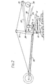
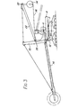
- FIG. 1 An example of a stacker-reclaimer according to the invention is illustrated schematically in the accompanying drawings, in which the machine is shown in Figs. 1-3 with the main boom in horizontal, raised and lowered positions respectively.
- the stacker-reclaimer comprises a carriage of entirely conventional form on which, in known manner, there is a luffing and slewing mounting comprising a slew mounting ring 2, a platform 4 rotatable about the vertical pivot axis of the slew ring 2 and a luffing pivot 6 with an axis intersecting the slew pivot axis.
- a boom structure 8 comprises a mast 10 which is mounted on the platform through the pivot 6 and a luffing drive hydraulic cylinder 12 forwards of the pivot.
- the boom structure Extending forwards from the mast the boom structure includes a main boom 14 supported in a fixed position relative to the mast by a pin connection 16 at its inner end and cables 18 between its outer end and the top of the mast.
- a belt conveyor 19 runs along the length of the boom and a bucket wheel 20 is rotatably mounted at the forward extremity of the boom.
- auxiliary tail boom 22 is attached to the mast and is also supported by cables 24 running from the top of the mast to its outer end.
- the tail boom is disposed thus, considerably higher than the main boom,in order to accommodate below it a conventional elevating conveyor 26 feeding the main boom conveyor through a hopper chute 28 when the machine is working in the stacking mode.
- the tail boom From a pivot 30 at its rear extremity the tail boom has a rigid arm 32 suspended, and a counterbalance weight 34 is fixed to the lower end of the arm.
- a cable 36 attached one end to the weight runs in a direction substantially parallel to the main boom over a pulley 38 on the mast at the level of the tail boom attachment and has its other end attached to an anchorage 40 on the platform 4 forwards of the luffing pivot 6.
- the luffing cylinder will experience greater variations of load to oppose the resulting variations in the cable tension. In general it is thus preferable to design for some variation of the moment of the weight 36 about the luffing pivot and so reduce the variation in cable tension. In this way, although luffing displacements of the boom structure and counterbalance weight will still produce varying loading on the slewing ring, both the luffing cylinder and the slewing ring can be subjected to smaller variations than they would experience if no counterbalance weight were provided and their maximum design loading can be reduced.
- the balance of forces is in any case preferably so arranged that the luffing cylinder is subject to some compression force at all times, as a fail-safe measure.
Landscapes
- Engineering & Computer Science (AREA)
- Mechanical Engineering (AREA)
- Catalysts (AREA)
- Jib Cranes (AREA)
- Framework For Endless Conveyors (AREA)
- Intermediate Stations On Conveyors (AREA)
- Replacement Of Web Rolls (AREA)
- Electrical Discharge Machining, Electrochemical Machining, And Combined Machining (AREA)
- Centrifugal Separators (AREA)
- Specific Conveyance Elements (AREA)
Priority Applications (1)
| Application Number | Priority Date | Filing Date | Title |
|---|---|---|---|
| AT85302467T ATE30568T1 (de) | 1984-04-12 | 1985-04-09 | Absetz- und aufnahmegeraet. |
Applications Claiming Priority (2)
| Application Number | Priority Date | Filing Date | Title |
|---|---|---|---|
| GB848409556A GB8409556D0 (en) | 1984-04-12 | 1984-04-12 | Stacker-reclaimer |
| GB8409556 | 1984-04-12 |
Publications (2)
| Publication Number | Publication Date |
|---|---|
| EP0164191A1 true EP0164191A1 (de) | 1985-12-11 |
| EP0164191B1 EP0164191B1 (de) | 1987-11-04 |
Family
ID=10559589
Family Applications (1)
| Application Number | Title | Priority Date | Filing Date |
|---|---|---|---|
| EP85302467A Expired EP0164191B1 (de) | 1984-04-12 | 1985-04-09 | Absetz- und Aufnahmegerät |
Country Status (11)
| Country | Link |
|---|---|
| US (1) | US4664271A (de) |
| EP (1) | EP0164191B1 (de) |
| JP (1) | JPS60232327A (de) |
| AT (1) | ATE30568T1 (de) |
| AU (1) | AU577497B2 (de) |
| CA (1) | CA1234068A (de) |
| DE (1) | DE3560893D1 (de) |
| GB (1) | GB8409556D0 (de) |
| IN (1) | IN164624B (de) |
| MX (1) | MX160928A (de) |
| ZA (1) | ZA852693B (de) |
Cited By (1)
| Publication number | Priority date | Publication date | Assignee | Title |
|---|---|---|---|---|
| CN103523542A (zh) * | 2013-11-01 | 2014-01-22 | 大连华锐重工集团股份有限公司 | 一种臂式斗轮堆取料机交叉式固定三尾车及其取料方法 |
Families Citing this family (7)
| Publication number | Priority date | Publication date | Assignee | Title |
|---|---|---|---|---|
| US5253771A (en) * | 1991-11-18 | 1993-10-19 | The United States Of America As Represented By The Administrator Of The National Aeronautics And Space Administration | Counter-balanced, multiple cable construction crane |
| US20140183003A1 (en) * | 2012-12-31 | 2014-07-03 | Caterpillar Inc. | Cold Planer with Aligned Transition Zone |
| US9010521B2 (en) | 2013-05-02 | 2015-04-21 | Skarlupka Mfg., Inc. | Counterbalanced elevating conveyor |
| CN103950737B (zh) * | 2014-04-30 | 2016-06-22 | 钦州学院 | 伺服驱动连杆机构式电动斗轮堆取料机 |
| CN106144651A (zh) * | 2016-08-23 | 2016-11-23 | 大连奇重机电成套设备有限公司 | 悬臂式斗轮堆取料机俯仰机构平衡检测装置 |
| JP6955448B2 (ja) * | 2018-01-11 | 2021-10-27 | 川崎重工業株式会社 | 荷役運搬機械 |
| SE2151601A1 (en) * | 2021-12-22 | 2023-06-23 | Wallbergs Aakeri I Hennan Ab | Mobile stacking machine |
Citations (5)
| Publication number | Priority date | Publication date | Assignee | Title |
|---|---|---|---|---|
| DE105168C (de) * | ||||
| GB402344A (en) * | 1933-05-12 | 1933-11-30 | William Hugh Watkins | Improvements in or relating to self-stabilising jib-cranes |
| DE1207284B (de) * | 1964-04-25 | 1965-12-16 | Beteiligungs & Patentverw Gmbh | Lagerplatz-Umschlaganlage |
| US3653486A (en) * | 1970-07-17 | 1972-04-04 | Dravo Corp | Material handling apparatus |
| DE2211078A1 (de) * | 1972-03-08 | 1973-09-13 | Babcock & Wilcox Ag | Kombiniertes geraet zum be- und rueckladen von lagerplaetzen fuer schuettgueter |
Family Cites Families (7)
| Publication number | Priority date | Publication date | Assignee | Title |
|---|---|---|---|---|
| US849078A (en) * | 1904-04-15 | 1907-04-02 | Lincoln Moss | Hoisting apparatus. |
| US2408500A (en) * | 1944-09-13 | 1946-10-01 | Maxwell A West | Automatic counterbalance for boom derricks |
| DE1484726A1 (de) * | 1964-09-10 | 1969-03-13 | Buckau Wolf Maschf R | Schaufelradschwenkbagger |
| US3530999A (en) * | 1967-12-01 | 1970-09-29 | Dravo Corp | Safety device for materials handling structures |
| US4004696A (en) * | 1975-10-17 | 1977-01-25 | Dravo Corporation | Material handling apparatus with load compensated counterweight system |
| US4407419A (en) * | 1981-12-30 | 1983-10-04 | Clements Shannon K | Portable boom support for vehicles |
| DE3207751C2 (de) * | 1982-03-04 | 1985-09-05 | Fried. Krupp Gmbh, 4300 Essen | Schaufelrad-Rückladegerät für Schüttguthalden |
-
1984
- 1984-04-12 GB GB848409556A patent/GB8409556D0/en active Pending
-
1985
- 1985-04-04 IN IN263/MAS/85A patent/IN164624B/en unknown
- 1985-04-09 DE DE8585302467T patent/DE3560893D1/de not_active Expired
- 1985-04-09 EP EP85302467A patent/EP0164191B1/de not_active Expired
- 1985-04-09 AT AT85302467T patent/ATE30568T1/de not_active IP Right Cessation
- 1985-04-09 CA CA000478671A patent/CA1234068A/en not_active Expired
- 1985-04-10 AU AU40976/85A patent/AU577497B2/en not_active Ceased
- 1985-04-10 US US06/721,657 patent/US4664271A/en not_active Expired - Fee Related
- 1985-04-11 MX MX204924A patent/MX160928A/es unknown
- 1985-04-11 ZA ZA852693A patent/ZA852693B/xx unknown
- 1985-04-12 JP JP60079159A patent/JPS60232327A/ja active Pending
Patent Citations (5)
| Publication number | Priority date | Publication date | Assignee | Title |
|---|---|---|---|---|
| DE105168C (de) * | ||||
| GB402344A (en) * | 1933-05-12 | 1933-11-30 | William Hugh Watkins | Improvements in or relating to self-stabilising jib-cranes |
| DE1207284B (de) * | 1964-04-25 | 1965-12-16 | Beteiligungs & Patentverw Gmbh | Lagerplatz-Umschlaganlage |
| US3653486A (en) * | 1970-07-17 | 1972-04-04 | Dravo Corp | Material handling apparatus |
| DE2211078A1 (de) * | 1972-03-08 | 1973-09-13 | Babcock & Wilcox Ag | Kombiniertes geraet zum be- und rueckladen von lagerplaetzen fuer schuettgueter |
Cited By (2)
| Publication number | Priority date | Publication date | Assignee | Title |
|---|---|---|---|---|
| CN103523542A (zh) * | 2013-11-01 | 2014-01-22 | 大连华锐重工集团股份有限公司 | 一种臂式斗轮堆取料机交叉式固定三尾车及其取料方法 |
| CN103523542B (zh) * | 2013-11-01 | 2015-07-08 | 大连华锐重工集团股份有限公司 | 一种臂式斗轮堆取料机交叉式固定三尾车及其取料方法 |
Also Published As
| Publication number | Publication date |
|---|---|
| AU4097685A (en) | 1985-10-17 |
| GB8409556D0 (en) | 1984-05-23 |
| MX160928A (es) | 1990-06-19 |
| CA1234068A (en) | 1988-03-15 |
| JPS60232327A (ja) | 1985-11-19 |
| ATE30568T1 (de) | 1987-11-15 |
| AU577497B2 (en) | 1988-09-22 |
| EP0164191B1 (de) | 1987-11-04 |
| ZA852693B (en) | 1985-11-27 |
| IN164624B (de) | 1989-04-22 |
| DE3560893D1 (en) | 1987-12-10 |
| US4664271A (en) | 1987-05-12 |
Similar Documents
| Publication | Publication Date | Title |
|---|---|---|
| EP0184386B1 (de) | Erdbewegungsmaschine mit Gegengewicht | |
| AU2006202566B2 (en) | Dragline bucket rigging and control apparatus | |
| EP0164191B1 (de) | Absetz- und Aufnahmegerät | |
| GB2109842A (en) | Movable cutting machine | |
| CA1182845A (en) | Installation for two or more step excavating in a discontinuous open cut operation | |
| US3700120A (en) | Apparatus for collecting and discharging lumber | |
| US4004696A (en) | Material handling apparatus with load compensated counterweight system | |
| US2870925A (en) | Apparatus for stocking small logs and picking up same from a stock for loading vehicles | |
| US3298117A (en) | Transloading device, especially bucket wheel transloading device | |
| US3206048A (en) | Shovel excavator | |
| US4260050A (en) | Pick-up and dump machine | |
| AU5352700A (en) | Fairlead mechanism | |
| EP0123466B1 (de) | Transfereinrichtung und Verfahren | |
| US3567049A (en) | Mechanical excavator or loader vehicle | |
| CN1005485B (zh) | 堆取料机 | |
| RU2768067C1 (ru) | Загрузочное устройство и пилон для загрузочного устройства | |
| US4278392A (en) | Log skidder with folding arch | |
| US4446958A (en) | Cross-pit conveyor | |
| US3754633A (en) | Gantry scraper | |
| EP3609824B1 (de) | Vorrichtung und verfahren zum kontinuierlichen entladen von nicht-kohärentem material für schiffsladeräume, lastkähne, lagerungskisten oder dergleichen | |
| US3972405A (en) | Reloading device | |
| JPS60223725A (ja) | 分割型ブームを持つ荷役機械 | |
| SU679519A1 (ru) | Погрузчик дл лесоматериалов | |
| SU899759A1 (ru) | Роторный экскаватор | |
| CN111646245A (zh) | 一种固定式装船输送机 |
Legal Events
| Date | Code | Title | Description |
|---|---|---|---|
| PUAI | Public reference made under article 153(3) epc to a published international application that has entered the european phase |
Free format text: ORIGINAL CODE: 0009012 |
|
| AK | Designated contracting states |
Designated state(s): AT BE DE FR GB IT NL SE |
|
| 17P | Request for examination filed |
Effective date: 19860205 |
|
| 17Q | First examination report despatched |
Effective date: 19860821 |
|
| GRAA | (expected) grant |
Free format text: ORIGINAL CODE: 0009210 |
|
| AK | Designated contracting states |
Kind code of ref document: B1 Designated state(s): AT BE DE FR GB IT NL SE |
|
| REF | Corresponds to: |
Ref document number: 30568 Country of ref document: AT Date of ref document: 19871115 Kind code of ref document: T |
|
| REF | Corresponds to: |
Ref document number: 3560893 Country of ref document: DE Date of ref document: 19871210 |
|
| ET | Fr: translation filed | ||
| ITF | It: translation for a ep patent filed | ||
| PLBE | No opposition filed within time limit |
Free format text: ORIGINAL CODE: 0009261 |
|
| STAA | Information on the status of an ep patent application or granted ep patent |
Free format text: STATUS: NO OPPOSITION FILED WITHIN TIME LIMIT |
|
| 26N | No opposition filed | ||
| PGFP | Annual fee paid to national office [announced via postgrant information from national office to epo] |
Ref country code: GB Payment date: 19890331 Year of fee payment: 5 |
|
| PGFP | Annual fee paid to national office [announced via postgrant information from national office to epo] |
Ref country code: FR Payment date: 19890417 Year of fee payment: 5 |
|
| PGFP | Annual fee paid to national office [announced via postgrant information from national office to epo] |
Ref country code: SE Payment date: 19890419 Year of fee payment: 5 |
|
| PGFP | Annual fee paid to national office [announced via postgrant information from national office to epo] |
Ref country code: DE Payment date: 19890420 Year of fee payment: 5 |
|
| PGFP | Annual fee paid to national office [announced via postgrant information from national office to epo] |
Ref country code: BE Payment date: 19890426 Year of fee payment: 5 |
|
| PGFP | Annual fee paid to national office [announced via postgrant information from national office to epo] |
Ref country code: AT Payment date: 19890428 Year of fee payment: 5 |
|
| ITTA | It: last paid annual fee | ||
| PGFP | Annual fee paid to national office [announced via postgrant information from national office to epo] |
Ref country code: NL Payment date: 19890430 Year of fee payment: 5 |
|
| PG25 | Lapsed in a contracting state [announced via postgrant information from national office to epo] |
Ref country code: GB Effective date: 19900409 Ref country code: AT Effective date: 19900409 |
|
| PG25 | Lapsed in a contracting state [announced via postgrant information from national office to epo] |
Ref country code: SE Effective date: 19900410 |
|
| PG25 | Lapsed in a contracting state [announced via postgrant information from national office to epo] |
Ref country code: BE Effective date: 19900430 |
|
| BERE | Be: lapsed |
Owner name: DRG (UK) LTD Effective date: 19900430 |
|
| PG25 | Lapsed in a contracting state [announced via postgrant information from national office to epo] |
Ref country code: NL Effective date: 19901101 |
|
| GBPC | Gb: european patent ceased through non-payment of renewal fee | ||
| NLV4 | Nl: lapsed or anulled due to non-payment of the annual fee | ||
| PG25 | Lapsed in a contracting state [announced via postgrant information from national office to epo] |
Ref country code: FR Effective date: 19901228 |
|
| PG25 | Lapsed in a contracting state [announced via postgrant information from national office to epo] |
Ref country code: DE Effective date: 19910101 |
|
| REG | Reference to a national code |
Ref country code: FR Ref legal event code: ST |
|
| EUG | Se: european patent has lapsed |
Ref document number: 85302467.7 Effective date: 19910116 |