EP0164332B1 - Elément de construction à épaisseur de paroi substantiellement constante - Google Patents
Elément de construction à épaisseur de paroi substantiellement constante Download PDFInfo
- Publication number
- EP0164332B1 EP0164332B1 EP85890098A EP85890098A EP0164332B1 EP 0164332 B1 EP0164332 B1 EP 0164332B1 EP 85890098 A EP85890098 A EP 85890098A EP 85890098 A EP85890098 A EP 85890098A EP 0164332 B1 EP0164332 B1 EP 0164332B1
- Authority
- EP
- European Patent Office
- Prior art keywords
- building component
- building
- component according
- reinforcement
- concrete
- Prior art date
- Legal status (The legal status is an assumption and is not a legal conclusion. Google has not performed a legal analysis and makes no representation as to the accuracy of the status listed.)
- Expired - Lifetime
Links
Images

Classifications
-
- E—FIXED CONSTRUCTIONS
- E04—BUILDING
- E04B—GENERAL BUILDING CONSTRUCTIONS; WALLS, e.g. PARTITIONS; ROOFS; FLOORS; CEILINGS; INSULATION OR OTHER PROTECTION OF BUILDINGS
- E04B2/00—Walls, e.g. partitions, for buildings; Wall construction with regard to insulation; Connections specially adapted to walls
- E04B2/84—Walls made by casting, pouring, or tamping in situ
- E04B2/86—Walls made by casting, pouring, or tamping in situ made in permanent forms
- E04B2/8611—Walls made by casting, pouring, or tamping in situ made in permanent forms with spacers being embedded in at least one form leaf
-
- E—FIXED CONSTRUCTIONS
- E04—BUILDING
- E04C—STRUCTURAL ELEMENTS; BUILDING MATERIALS
- E04C2/00—Building elements of relatively thin form for the construction of parts of buildings, e.g. sheet materials, slabs, or panels
- E04C2/02—Building elements of relatively thin form for the construction of parts of buildings, e.g. sheet materials, slabs, or panels characterised by specified materials
- E04C2/10—Building elements of relatively thin form for the construction of parts of buildings, e.g. sheet materials, slabs, or panels characterised by specified materials of wood, fibres, chips, vegetable stems, or the like; of plastics; of foamed products
- E04C2/20—Building elements of relatively thin form for the construction of parts of buildings, e.g. sheet materials, slabs, or panels characterised by specified materials of wood, fibres, chips, vegetable stems, or the like; of plastics; of foamed products of plastics
- E04C2/22—Building elements of relatively thin form for the construction of parts of buildings, e.g. sheet materials, slabs, or panels characterised by specified materials of wood, fibres, chips, vegetable stems, or the like; of plastics; of foamed products of plastics reinforced
-
- E—FIXED CONSTRUCTIONS
- E04—BUILDING
- E04B—GENERAL BUILDING CONSTRUCTIONS; WALLS, e.g. PARTITIONS; ROOFS; FLOORS; CEILINGS; INSULATION OR OTHER PROTECTION OF BUILDINGS
- E04B2/00—Walls, e.g. partitions, for buildings; Wall construction with regard to insulation; Connections specially adapted to walls
- E04B2/84—Walls made by casting, pouring, or tamping in situ
- E04B2/86—Walls made by casting, pouring, or tamping in situ made in permanent forms
- E04B2002/8682—Mixed technique using permanent and reusable forms
Definitions
- the invention relates to a component according to the preamble of claim 1, which can be designed not only as a flat component, such as a building board, but also as another component in a flat or spatial shape and in which stiffening ribs are optionally provided in regions or continuously.
- a component according to the preamble of claim 1 is known from DE-U-1 914 808.
- This known component forms a wall or ceiling plate made of foamed plastic, which can be used in particular for living rooms.
- the reinforcement insert can be made of metal or plastic and is preferably glued between two foam sheets. It is assumed that the reinforcement inserts consist of a flexible material which remains in the bent shape after the bending, so that the plate can be deformed by bending and maintains this shape after the release by the bending tool.
- the basic idea is to form a support structure from the reinforcement insert, which essentially determines the strength and here the deformation resistance of the plate. There are hardly any positive interactions to be expected between the plate material and the reinforcement insert, and it is also not intended to use the inserts provided in the middle of the plate thickness for anchoring the plates or for connecting these plates to other elements.
- DE-U-7 707 477 relates to makeshift structures in which a building structure is constructed in accordance with the intended walls, barrel vaults, etc. from nets and supports, in particular metal nets, and then a layer of closed-cell plastic foam, in particular polyurethane foam, is applied to provide thermal insulation to obtain heat-insulating sandwich construction.
- a building board made of grid-reinforced foam is known, in which the grid is located at a distance from the surface of the foam body on the outside of the board and is supported on the foam body by spacers. This grid serves as reinforcement for a subsequent layer of plaster to be applied.
- Building boards made of hardenable synthetic resin reinforced by glass fiber mats or chopped glass fibers are also known.
- pipes made of concrete, stoneware and thermoplastic materials in particular for waste water or aggressive media
- pipes made of hardenable synthetic resin, which can be reinforced with glass fibers are also known.
- the tensile strength of these materials is relatively low and there are therefore greater wall thicknesses with larger pipe dimensions.
- the object of the invention is to provide a component which is versatile, has a favorable strength-weight ratio, is resistant to aggressive media and, if necessary, can be combined with other components to form composite elements.
- the surface reinforcement is preferably made of metal and can be made of structural steel, in particular a structural steel mesh mat.
- the surface reinforcement can also consist wholly or partly of glass fiber strands, in particular rovings or ropes.
- the component can be made in one or more layers, in full or in cavity or sandwich construction.
- Usual resins used for the component z. B. polyester have a much higher coefficient of thermal expansion than most metals and of course also as glass fibers.
- the flat reinforcement in the component according to the invention now prevents the synthetic resin material in which it is embedded from expanding to a greater extent, at the same time stressing the surface reinforcement. This ensures the shape of the component.
- the tensile, compressive and flexural strength of the component is increased compared to an element of the same strength, which was only made from the appropriate synthetic resin.
- the reinforcement is embedded in the material and therefore protected against corrosion.
- the component can be combined with further, flat adjoining components to form a composite or sandwich element.
- a single or multi-layer insert would be present between two plate-shaped components.
- Areas of application for such a component would be use as a cladding element for walls and facades with a possibly differently structured surface, as formwork panel or lost formwork element for concrete or concrete parts, as a protective panel against mechanical or chemical influences, for example as a cover panel in landfills and silos, as a gutter-shaped component Manufacture of irrigation and drainage channels, whereby corresponding gutter sections can also be assembled from several components, as a cover plate for openings and gutters, as a self-supporting structural element of any shape, as a structural element, shape or lost formwork for wall, ceiling and floor constructions and finally as a self-supporting covering irrigation channels or trenches in tropical areas.
- the component has improved impact resistance compared to elements made of concrete, etc.
- the respective component through the channel edges connecting tension members is held in the channel shape.
- the component can also be placed in a still flowable mortar or concrete bed, so that a concreted channel is formed in which the liquid flows on the component, that is, on the plastic part.
- the channel edges can be connected by a film that closes the channel opening.
- This includes an insulating cavity with the gutter, so that when covering irrigation channels or trenches the heating of the water and the air layer located directly above the water on the cover irradiated by the sun is avoided and thus the evaporation losses that otherwise occur are decisive be reduced.
- the component is designed as a pipe or pipe shell, with increased strength being achieved by the surface reinforcement, so that the wall thickness can be significantly reduced compared to the previously known unreinforced pipes for the same tasks and even open up new areas of application.
- the embedded surface reinforcement is a prestressed ring reinforcement. The prestressing is simply done in such a way that the reinforcement is prestressed during manufacture and the prestress is frozen when the synthetic resin is subsequently hardened.
- the reinforcement from the flat part of the component can be connected to the surface reinforcement, which are usually arranged approximately normal to the surface of the element from which they are led out, in principle with this surface if necessary but can include different angles.
- the element is designed as a lost formwork or form in which the entire reinforcement of the composite body to be finished by pouring or pouring concrete or the like is determined by the surface reinforcement and the stiffening elements connected to it.
- This variant opens up a wide range of applications. It becomes possible to predetermine the basic shape of composite components by means of corresponding lost shapes or formwork, it being possible for these latter parts to be manufactured in the factory. Pouring with concrete or the like only takes place at or near the place of use. This allows the advantages of prefabricated components to be achieved for many areas of application without having to accept the previous disadvantages of transporting heavy finished parts over long distances. Compared with precast concrete parts, when using construction elements according to the invention as lost formwork or form, smaller manufacturing tolerances with better shape retention can be achieved with simple means and in particular it is also possible to form connection folds, flanges etc. precisely, the areas of the plastic component intended for connection to other parts can be formed.
- curbs can also be used to manufacture load-bearing concrete parts in composite construction using components according to the invention as formwork or form, with the advantages already mentioned having the decisive advantage that the formwork or form forming a skin of the finished composite body makes the penetration more aggressive Media in the concrete core and in particular also prevents the attack of the metal reinforcement by liquid containing chlorine ions, which has hitherto been practically unavoidable with conventional salt scattering to prevent ice formation.
- the attachment of the entire reinforcement to the prefabricated element also facilitates z. B. in the production of concrete slabs for the construction of silos, landfills, etc. the final production, since it is only necessary to pour the corresponding, prefabricated molds with concrete of a prescribed minimum quality class.
- adjacent elements that form a lost formwork or form can be connected to larger units before the pouring or pouring out via stiffening elements attached in the edge region.
- stiffening elements that protrude from the flat part of the structural element are made of metal, they can be coated with the hardenable synthetic resin and thus be protected from the entry of aggressive media in addition to being embedded in the concrete.
- stiffening elements of the tube can be designed as bi-steels, slot irons or similar elements arranged in the longitudinal direction of the tube and radially aligned.
- the passage opening has a lining made of the plastic component, wherein this is a reinforcement. It is a manufacturer development of the pipes with floor finishers or by centrifugal casting.
- tubular components Another area of application of the tubular components is in the subsequent renovation of already existing channels and pipelines, in particular sewage pipes.
- Combined processes are also possible in which the pipe is attached to the duct opening and the gap to the duct opening is sealed at the pipe end, after which concrete mortar is pressed into the annular gap under pressure, through which the pipe is then drawn into the duct as with the aid of an annular piston .
- the component consists of a plate-shaped, flat body 1 made of glass fiber reinforced, curable synthetic resin, for. B. polyester, which is heated and pressed for the curing process.
- a surface reinforcement for example a structural steel mesh 2, is embedded in the body 1.
- the component 1 has a surface profile 3 on the visible side and is connected flatly to an insulating plate 4 on the other side.
- a series of components 6 according to the invention is provided for covering an irrigation channel 5, which are shaped here to form inverted gutter-shaped, angular, self-supporting components.
- a plate-shaped component 7 can be transported to the place of use as a flat plate and then bent into a channel, the component 7 being held in the intended shape by tension members 8.
- the tension members 8 are connected to the edges of the component 7 by slip-on shoes 9.
- slip-on shoes 9 instead of a plurality of spaced-apart tension members or in addition to the tension members 8, one can also provide a film which closes the entire channel opening and connects the channel edges again, so that it encloses a closed, insulating cavity with the plate 7.
- the shape of the arch formed from the plate 7 can be determined by the length of the tension members 8 and also by the reinforcement or a special cross-sectional shape of the plate 7. If necessary, you can also form predetermined bending points in the plate 7.
- a component 10 again made of synthetic resin, with a flat reinforcement 11 from a structural steel grid forms a lost formwork or a pourable form for a concrete body.
- a surface reinforcement 11 protruding stiffening elements in the form of Bi-steels 12 are connected from the areal part of the component 10, in which one leg 12a is welded to the structural steel grid 11.
- These bi-steels 12 connect the component 10 to the finished concrete body 13, the overall body formed having an overall strength determined by the reinforcement and the strength of the parts 10 and 13.
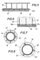
- tubular components 19 which again have a prestressed ring reinforcement 20, if necessary.
- the tubular components are combined to form a closed tube string and centered with the aid of at least three inflatable tubes 21.
- the annular gap 22 is then filled with concrete or mortar under pressure. After the concrete or mortar has been tightened, the hoses 21 are either pulled out, after which the cavities left free by them are sprayed out, or the hoses are left in place and then spray it out with concrete, mortar or sealant.
Landscapes
- Engineering & Computer Science (AREA)
- Architecture (AREA)
- Civil Engineering (AREA)
- Structural Engineering (AREA)
- Life Sciences & Earth Sciences (AREA)
- Electromagnetism (AREA)
- Physics & Mathematics (AREA)
- Wood Science & Technology (AREA)
- Laminated Bodies (AREA)
- Forms Removed On Construction Sites Or Auxiliary Members Thereof (AREA)
- Panels For Use In Building Construction (AREA)
- Reinforcement Elements For Buildings (AREA)
- Transition And Organic Metals Composition Catalysts For Addition Polymerization (AREA)
- Finishing Walls (AREA)
- Manufacturing Of Tubular Articles Or Embedded Moulded Articles (AREA)
Claims (14)
Applications Claiming Priority (2)
| Application Number | Priority Date | Filing Date | Title |
|---|---|---|---|
| AT0185584A AT390632B (de) | 1984-06-06 | 1984-06-06 | Flaechenhaftes bauelement, insbesondere bauplatte |
| AT1855/84 | 1984-06-06 |
Publications (3)
| Publication Number | Publication Date |
|---|---|
| EP0164332A2 EP0164332A2 (fr) | 1985-12-11 |
| EP0164332A3 EP0164332A3 (en) | 1988-06-22 |
| EP0164332B1 true EP0164332B1 (fr) | 1991-01-23 |
Family
ID=3522461
Family Applications (1)
| Application Number | Title | Priority Date | Filing Date |
|---|---|---|---|
| EP85890098A Expired - Lifetime EP0164332B1 (fr) | 1984-06-06 | 1985-04-25 | Elément de construction à épaisseur de paroi substantiellement constante |
Country Status (3)
| Country | Link |
|---|---|
| EP (1) | EP0164332B1 (fr) |
| AT (2) | AT390632B (fr) |
| DE (1) | DE3581427D1 (fr) |
Families Citing this family (5)
| Publication number | Priority date | Publication date | Assignee | Title |
|---|---|---|---|---|
| IT1199777B (it) * | 1986-12-12 | 1988-12-30 | R E In S P A | Procedimento per la coibentazione di facciate di edifici esistenti e pannello prefabbricato utilizzabile per l'attuazione di detto procedimento |
| GB8820915D0 (en) * | 1988-09-06 | 1988-10-05 | Ruswroe Ltd | Constructional member & method |
| US5538785A (en) * | 1990-11-14 | 1996-07-23 | Dingler; Gerhard | Construction element |
| AT395331B (de) * | 1990-01-31 | 1992-11-25 | Schuster Franz | Bauelementensatz zum abdichten von kanaelen u.dgl. |
| US6470639B1 (en) * | 2000-01-21 | 2002-10-29 | Jack Horn | Exterior window shutters |
Family Cites Families (4)
| Publication number | Priority date | Publication date | Assignee | Title |
|---|---|---|---|---|
| DE1914808U (de) * | 1965-02-04 | 1965-04-29 | Alfred Weiler | Wand- oder deckenplatte aus geschaeumtem kunststoff oder gummi fuer wohnraeume u. dgl. |
| DE2024453A1 (de) * | 1970-05-20 | 1971-12-09 | Arbed S.A. Arbed - Feiten & Guilleaume Vereinigte Drahtwerke, 5000 Köln-Mülheim | Hochfestes, stab- oder flächenförmiges Bauteil |
| DE7707477U1 (de) * | 1977-03-11 | 1978-10-12 | Ingeniosa Ag, Chur (Schweiz) | Hochisolierendes selbsttragendes wand- und deckenelement |
| AT370169B (de) * | 1980-03-26 | 1983-03-10 | Joh Fuchs & Sohn Ges M B H | Bauplatte zur mauerwerksverkleidung |
-
1984
- 1984-06-06 AT AT0185584A patent/AT390632B/de not_active IP Right Cessation
-
1985
- 1985-04-25 EP EP85890098A patent/EP0164332B1/fr not_active Expired - Lifetime
- 1985-04-25 DE DE8585890098T patent/DE3581427D1/de not_active Expired - Lifetime
- 1985-04-25 AT AT85890098T patent/ATE60389T1/de not_active IP Right Cessation
Also Published As
| Publication number | Publication date |
|---|---|
| AT390632B (de) | 1990-06-11 |
| DE3581427D1 (de) | 1991-02-28 |
| ATE60389T1 (de) | 1991-02-15 |
| ATA185584A (de) | 1989-11-15 |
| EP0164332A3 (en) | 1988-06-22 |
| EP0164332A2 (fr) | 1985-12-11 |
Similar Documents
| Publication | Publication Date | Title |
|---|---|---|
| EP0757137A1 (fr) | Coffrage | |
| EP3191657B1 (fr) | Coffrage perdu en béton haute performance ou ultra haute performance | |
| WO2019166039A1 (fr) | Module et procédé de fabrication d'un module, d'une paroi de bâtiment et d'un bâtiment | |
| DE2438890A1 (de) | Vorgefertigte elemente fuer trennwaende und mauerwerke und mit derartigen elementen gebaute mauern und waende | |
| DE3602537C2 (de) | Verfahren zum Herstellen mehrschichtiger, plattenförmiger Fertigteilbauelemente | |
| EP1712696B1 (fr) | Mur préfabriqué isolé avec épingles | |
| DE102008017897A1 (de) | Pufferspeicher für den Wärmeträger zumindest eines Wärmeverbrauchers, insbesondere Warmwasserspeicher eines Mehrfamilienhauses | |
| DE69322662T2 (de) | Gebäudewand, verfahren zum errichten einer solchen wand und element hierfür | |
| EP0164332A2 (fr) | Elément de construction à épaisseur de paroi substantiellement constante | |
| DE2946346A1 (de) | Verfahren zur herstellung vorgefertigter platten und danach hergestellte platten | |
| DE10120368B4 (de) | Gebäude oder Gebäudeteil sowie Verfahren zu dessen Herstellung und Abbau | |
| DE2716407A1 (de) | Verfahren und vorrichtung zur herstellung von vorgefertigten wand- und deckenteilen fuer bauwerke | |
| WO1994017258A1 (fr) | Element de construction | |
| EP2122075B1 (fr) | Élément de construction à coffrage intérieur | |
| DE10235044A1 (de) | Verfahren zur Herstellung von Hohlräumen in aushärtbaren Massen, insbesondere in Betonelementen | |
| DE29521347U1 (de) | Wiederverwendbares Schalungssystem für zylinderförmige oder prismatische Betonsäulen | |
| DE29602697U1 (de) | Schalung | |
| DE102024111006B4 (de) | Hohldeckenplatte und Verfahren zu ihrer Herstellung | |
| DE8911453U1 (de) | Flächen-Bauelement, insbesondere zur Herstellung von Decken, Wänden und dergleichen | |
| DE3932058A1 (de) | Verfahren zum herstellen vorgefertigter flaechen-bauelemente | |
| DE102012021213A1 (de) | Randschalungselement und Randschalungs-Verfahren | |
| DE68904776T2 (de) | Bauglied und verfahren. | |
| DE1939150B2 (de) | Verfahren zum Herstellen eines mindestens doppelwandigen Heizölbehälters in sphärischer oJL Form | |
| EP0757141B1 (fr) | Coffrage pour cheminée | |
| EP0063616B1 (fr) | Tuyauterie en béton coulé in-situ et méthode pour sa production |
Legal Events
| Date | Code | Title | Description |
|---|---|---|---|
| PUAI | Public reference made under article 153(3) epc to a published international application that has entered the european phase |
Free format text: ORIGINAL CODE: 0009012 |
|
| AK | Designated contracting states |
Designated state(s): AT BE CH DE FR GB IT LI LU NL SE |
|
| RAP1 | Party data changed (applicant data changed or rights of an application transferred) |
Owner name: BAUER-AGRARTECHNIK GESELLSCHAFT M.B.H. |
|
| PUAL | Search report despatched |
Free format text: ORIGINAL CODE: 0009013 |
|
| AK | Designated contracting states |
Kind code of ref document: A3 Designated state(s): AT BE CH DE FR GB IT LI LU NL SE |
|
| DIN1 | Information on inventor provided before grant (deleted) | ||
| RAP1 | Party data changed (applicant data changed or rights of an application transferred) |
Owner name: SCHUSTER, FRANZ, DIPL.-ING. |
|
| RIN1 | Information on inventor provided before grant (corrected) |
Inventor name: SCHUSTER, FRANZ, DIPL.-ING. |
|
| 17P | Request for examination filed |
Effective date: 19881123 |
|
| 17Q | First examination report despatched |
Effective date: 19891201 |
|
| GRAA | (expected) grant |
Free format text: ORIGINAL CODE: 0009210 |
|
| AK | Designated contracting states |
Kind code of ref document: B1 Designated state(s): AT BE CH DE FR GB IT LI LU NL SE |
|
| REF | Corresponds to: |
Ref document number: 60389 Country of ref document: AT Date of ref document: 19910215 Kind code of ref document: T |
|
| REF | Corresponds to: |
Ref document number: 3581427 Country of ref document: DE Date of ref document: 19910228 |
|
| ITF | It: translation for a ep patent filed | ||
| GBT | Gb: translation of ep patent filed (gb section 77(6)(a)/1977) | ||
| ET | Fr: translation filed | ||
| PLBE | No opposition filed within time limit |
Free format text: ORIGINAL CODE: 0009261 |
|
| STAA | Information on the status of an ep patent application or granted ep patent |
Free format text: STATUS: NO OPPOSITION FILED WITHIN TIME LIMIT |
|
| 26N | No opposition filed | ||
| EPTA | Lu: last paid annual fee | ||
| EAL | Se: european patent in force in sweden |
Ref document number: 85890098.8 |
|
| NLS | Nl: assignments of ep-patents |
Owner name: ANGERLEHNER HOCH- UND TIEFBAU GMBH |
|
| REG | Reference to a national code |
Ref country code: FR Ref legal event code: TP |
|
| REG | Reference to a national code |
Ref country code: CH Ref legal event code: PUE Owner name: DIPL.-ING. FRANZ SCHUSTER TRANSFER- ANGERLEHNER HO |
|
| REG | Reference to a national code |
Ref country code: GB Ref legal event code: 732E |
|
| PGFP | Annual fee paid to national office [announced via postgrant information from national office to epo] |
Ref country code: GB Payment date: 20000313 Year of fee payment: 16 |
|
| PGFP | Annual fee paid to national office [announced via postgrant information from national office to epo] |
Ref country code: SE Payment date: 20000320 Year of fee payment: 16 Ref country code: NL Payment date: 20000320 Year of fee payment: 16 |
|
| PGFP | Annual fee paid to national office [announced via postgrant information from national office to epo] |
Ref country code: CH Payment date: 20000323 Year of fee payment: 16 |
|
| PGFP | Annual fee paid to national office [announced via postgrant information from national office to epo] |
Ref country code: FR Payment date: 20000327 Year of fee payment: 16 |
|
| PGFP | Annual fee paid to national office [announced via postgrant information from national office to epo] |
Ref country code: LU Payment date: 20000404 Year of fee payment: 16 |
|
| PGFP | Annual fee paid to national office [announced via postgrant information from national office to epo] |
Ref country code: BE Payment date: 20000405 Year of fee payment: 16 |
|
| PGFP | Annual fee paid to national office [announced via postgrant information from national office to epo] |
Ref country code: AT Payment date: 20010328 Year of fee payment: 17 |
|
| PGFP | Annual fee paid to national office [announced via postgrant information from national office to epo] |
Ref country code: DE Payment date: 20010421 Year of fee payment: 17 |
|
| PG25 | Lapsed in a contracting state [announced via postgrant information from national office to epo] |
Ref country code: LU Free format text: LAPSE BECAUSE OF NON-PAYMENT OF DUE FEES Effective date: 20010425 Ref country code: GB Free format text: LAPSE BECAUSE OF NON-PAYMENT OF DUE FEES Effective date: 20010425 |
|
| PG25 | Lapsed in a contracting state [announced via postgrant information from national office to epo] |
Ref country code: SE Free format text: LAPSE BECAUSE OF NON-PAYMENT OF DUE FEES Effective date: 20010426 |
|
| PG25 | Lapsed in a contracting state [announced via postgrant information from national office to epo] |
Ref country code: FR Free format text: THE PATENT HAS BEEN ANNULLED BY A DECISION OF A NATIONAL AUTHORITY Effective date: 20010430 Ref country code: BE Free format text: LAPSE BECAUSE OF NON-PAYMENT OF DUE FEES Effective date: 20010430 |
|
| PG25 | Lapsed in a contracting state [announced via postgrant information from national office to epo] |
Ref country code: LI Free format text: LAPSE BECAUSE OF NON-PAYMENT OF DUE FEES Effective date: 20010524 Ref country code: CH Free format text: LAPSE BECAUSE OF NON-PAYMENT OF DUE FEES Effective date: 20010524 |
|
| BERE | Be: lapsed |
Owner name: ANGERLEHNER HOCH- UND TIEFBAU G.M.B.H. Effective date: 20010430 |
|
| PG25 | Lapsed in a contracting state [announced via postgrant information from national office to epo] |
Ref country code: NL Free format text: LAPSE BECAUSE OF NON-PAYMENT OF DUE FEES Effective date: 20011101 |
|
| EUG | Se: european patent has lapsed |
Ref document number: 85890098.8 |
|
| GBPC | Gb: european patent ceased through non-payment of renewal fee |
Effective date: 20010425 |
|
| REG | Reference to a national code |
Ref country code: CH Ref legal event code: PL |
|
| NLV4 | Nl: lapsed or anulled due to non-payment of the annual fee |
Effective date: 20011101 |
|
| REG | Reference to a national code |
Ref country code: FR Ref legal event code: ST |
|
| PG25 | Lapsed in a contracting state [announced via postgrant information from national office to epo] |
Ref country code: AT Free format text: LAPSE BECAUSE OF NON-PAYMENT OF DUE FEES Effective date: 20020425 |
|
| PG25 | Lapsed in a contracting state [announced via postgrant information from national office to epo] |
Ref country code: DE Free format text: LAPSE BECAUSE OF NON-PAYMENT OF DUE FEES Effective date: 20021101 |