EP0164487A1 - Métier à tricoter rectiligne pour la fabrication de tricot intarsia - Google Patents
Métier à tricoter rectiligne pour la fabrication de tricot intarsia Download PDFInfo
- Publication number
- EP0164487A1 EP0164487A1 EP85100157A EP85100157A EP0164487A1 EP 0164487 A1 EP0164487 A1 EP 0164487A1 EP 85100157 A EP85100157 A EP 85100157A EP 85100157 A EP85100157 A EP 85100157A EP 0164487 A1 EP0164487 A1 EP 0164487A1
- Authority
- EP
- European Patent Office
- Prior art keywords
- thread
- thread guide
- knitting machine
- flat knitting
- carriage
- Prior art date
- Legal status (The legal status is an assumption and is not a legal conclusion. Google has not performed a legal analysis and makes no representation as to the accuracy of the status listed.)
- Withdrawn
Links
- 238000009940 knitting Methods 0.000 title claims abstract description 32
- 238000004519 manufacturing process Methods 0.000 title claims description 6
- 238000003825 pressing Methods 0.000 claims description 38
- 230000007704 transition Effects 0.000 abstract description 10
- 230000000717 retained effect Effects 0.000 abstract 1
- 230000000694 effects Effects 0.000 description 4
- 238000003780 insertion Methods 0.000 description 3
- 230000037431 insertion Effects 0.000 description 3
- 238000011161 development Methods 0.000 description 2
- 230000018109 developmental process Effects 0.000 description 2
- 230000000630 rising effect Effects 0.000 description 2
- 230000001174 ascending effect Effects 0.000 description 1
- 230000000994 depressogenic effect Effects 0.000 description 1
- 238000006073 displacement reaction Methods 0.000 description 1
- 239000004744 fabric Substances 0.000 description 1
- 230000005294 ferromagnetic effect Effects 0.000 description 1
- 230000002452 interceptive effect Effects 0.000 description 1
- 230000009191 jumping Effects 0.000 description 1
- 238000012423 maintenance Methods 0.000 description 1
- 238000000926 separation method Methods 0.000 description 1
- 238000003892 spreading Methods 0.000 description 1
- 238000003860 storage Methods 0.000 description 1
Images


Classifications
-
- D—TEXTILES; PAPER
- D04—BRAIDING; LACE-MAKING; KNITTING; TRIMMINGS; NON-WOVEN FABRICS
- D04B—KNITTING
- D04B7/00—Flat-bed knitting machines with independently-movable needles
- D04B7/24—Flat-bed knitting machines with independently-movable needles for producing patterned fabrics
- D04B7/26—Flat-bed knitting machines with independently-movable needles for producing patterned fabrics with colour patterns
-
- D—TEXTILES; PAPER
- D04—BRAIDING; LACE-MAKING; KNITTING; TRIMMINGS; NON-WOVEN FABRICS
- D04B—KNITTING
- D04B15/00—Details of, or auxiliary devices incorporated in, weft knitting machines, restricted to machines of this kind
- D04B15/38—Devices for supplying, feeding, or guiding threads to needles
- D04B15/54—Thread guides
- D04B15/56—Thread guides for flat-bed knitting machines
Definitions
- the thread guides are displaceable and / or pivotable on the thread guide box in question between a lower thread insertion position holding the thread in the thread pull-in area of the needles and an upper rest position.
- the in the thread guide entering the lowered thread-in position must first be raised to its rest position before the thread guide assigned to the adjacent inlaid field and previously in the raised rest position can be lowered into its thread-in position in order to avoid mutual interference of the two thread guides lowered in the thread-in position.
- the invention has for its object to provide a flat knitting machine of the type described in the introduction, in connection with a faultless inlaid knitwear with clean inlaid field transitions and an increased operating speed of the device. and control effort for achieving the transitions from one inlaid field to another is also significantly reduced with any number of inlaid fields.
- thread guides assigned to the individual inlaid fields are fixed to the corresponding thread guide boxes in working positions raised to such an extent that they do not impede one another and that thread counters are provided on the slide of the flat knitting machine, which are in the area of one or more end needles of the inlaid fields, temporarily press the thread running between a needle of the inlaid field and the assigned thread guide stopped in the end position into the needle feed area.
- thread countersinks are additionally provided on the carriage of the flat knitting machine, which thread runs steeply upwards between a needle of the inlaid field and the associated thread guide, which is stopped in the end position against the thread guide limiter, into the needle feed region, that is to say into one position in which this thread can also be gripped by the last needle intended for it.
- the thread countersinks on the carriage of the flat knitting machine can be designed, stored and controlled in any way.
- the thread countersinks consist of at least one thread push-off plate that can be adjusted in each running direction of the slide and that follows the thread guides.
- two thread pressing plates are arranged on the carriage in the longitudinal direction of the needle bed at a distance from one another, which alternately do not engage one with the thread coming rest position and can be moved into a working position that depresses the thread into the feed area of the needles.
- Each thread pressing plate preferably has a thread deflecting edge which is in the front in the assigned running direction of the slide and is in particular beveled stepwise to the rear.
- the thread pressing plates of the thread countersink can be slidably or pivotably mounted on the slide transversely to their plane between a retracted rest position and a projecting working position. However, it is also possible to pivot the thread pressing plates parallel to their plane between a raised rest position and a lowered working position on the slide.
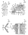
- B denotes the two needle beds of a two-bed flat knitting machine for the production of inlaid knitwear.
- an inlaid knit M is to be knitted with three immediately adjacent inlaid fields Ml, M2 and M3.
- a separate thread guide Gl, G2, G3 is assigned to each inlay field M1, M2, M3.
- Each thread guide Gl, G2, G3 can be moved with its thread guide box 1 between two thread guide limiters El, Ell or E2, E22 or E3, E33 provided in the end areas of the assigned inlay field Ml, M2, M3.
- the outer thread guide limiters El and E33 shown in dashed lines in FIG. 4 determine the lateral edges of the inlaid knit piece M.
- the pairs of thread limiters E2, Ell and E3, E22 determine the separation lines Tl and T2 between the inlaid fields Ml and M2 or M2 and M3 and M3.
- the thread guide limiters El, Ell or E2, E22 or E3, E33 assigned to each thread guide Gl, G2, G3 are arranged on the same side of the thread guide rail 2 on which the thread guide box 1 of the relevant thread guide Gl, G2, G3 also lies.
- 6 is the thread guide box on the right side of the thread guide rail 2 1 of a yarn guide and, more generally denoted by G on the other side of the yarn guide rail 2 with the designated E F aden devisbegrenzer for the thread guide of an adjacent inlaid field represented in general.
- the thread guide box 1 of the thread guide G is shown partly in section along the line VV in FIG. 5 and the thread guide limiter E partly in section along the line VI-VI in FIG. 5.
- the threads running from the individual thread guides Gl, G2, G3 to the inlaid fields M1, M2, M3 in question, for example differently colored threads, are denoted by Al, A2 and A3.
- the two thread guide limiters E2, E11 or E3, E22 assigned to a dividing line T1 or T2 between two intarsia fields M1, M2 or M2, M3 can be adjusted together on the thread guide rail 2 using any adjusting means in order to adjust the position or the course of the relevant dividing line T1 or T2, ie to change the width of the inlay fields Ml, M2, M3.
- the thread guide limiter pairs E2, Ell and E3, E22 e.g. with the aid of adjusting rods 3 which are slidably mounted in corresponding upper and / or lower longitudinal grooves of the thread guide rail 2 and dashed in Fig. 6 or indicated in Fig. 4 with a double arrow and a subsequent dash-dot line.
- the thread guides of neighboring inlaid fields lay their thread together over one or several needles, which creates a stitch weave.
- the thread guide GI assigned to the inlay field MI during the carriage stroke in the running direction Fl, ie to the right in FIG. 3, places its thread AI beyond the dividing line Tl between the two inlay fields Ml and M2 around the adjacent terminating needle N2 of the subsequent inlay field M2, as shown schematically in Fig. 3.
- the threading of the thread guide Gl then begins with the end needle N1 of the assigned inlay field Ml.
- the thread guide G2 assigned to the inlaid field M2 similarly puts its thread A2 over the dividing line Tl between the two inlaid fields M2, Ml around the adjacent terminating needle N1 during the carriage stroke in the direction of travel F2, ie to the left in FIG. 3 of the inlay field Ml.
- the threading of the thread guide G2 begins with the end needle N2 of the inlaid field M2.
- the thread guides G1 and G2 assigned to them therefore place their threads Al and A2 together around the terminating needle N2 of the inlaid field M2 in the carriage running direction Fl and around the terminating needle Nl of the inlaid field Ml in the carriage running direction F2.
- a thread guide box J. of a thread guide G which is mounted in a longitudinally displaceable manner, has on its upper side a rectangular recess delimited by two driving stages 4, 104, into which the spring-loaded driver bolt 6, which is arranged in the vertical direction and can be displaced on the carriage 5 of the flat knitting machine, can engage .
- Attached to the thread guide box 1 is a downward, rod-shaped thread guide holder 7, which carries the actual thread guide G, for example a tube, at its lower end, as is also shown in FIG. 11 for the thread guide G2.
- a lever 21 is pivotally mounted about an axis of rotation 20, the upper end of which engages with a transverse pin 22 in a vertical slot 23 of the slide 15.
- the slide 15 and the lever 21 are in their standby position shown in solid lines in FIG. 5, in which the end of the push rod 24 of the thread guide box 1 stopped in the end position against the stop body 11 lies just before the lower end 121 of the lever 21.
- the lever 21 is also pivoted from its standby position shown in solid lines in FIG. 5 into its feed position shown in dashed and dotted lines, in which it, with its lower end 121, the thread guide box 1 via the bumper 24 connected to it to the left in FIG. 5 presses a needle pitch away from the stop body 11 of the thread guide limiter E into a position in which the thread guide carried by the thread guide holder 7 places the thread Al around the terminating needle Nl of the assigned inlaid field Ml according to FIG. 3.
- the driver pin 6 of the carriage is then pressed upwards by the ramp 214 of the ramp 14 and thereby lifted from the upper driving projection 115 of the slide 15. Subsequently, the driving pin 6 slides on the descending run-up slope 314 of the runner 14, then on the horizontal upper right edge 215 of the drive projection 115 of the slider 15 and finally on the horizontal upper run edge 614 and the descending run-up slope 414 of the runner 14 and leaves it Thread guide limiter E.
- the driver pin 6 of the carriage first meets the thread guide limiter E and is raised resiliently by the ramp slope 414 of the winder 14 rising in this running direction up to its horizontal upper edge 614.
- the lever 21 is correspondingly pivoted from its feed position shown in broken lines in FIG. 5 into its ready position shown with solid lines.
- the working position of the individual thread guides Gl, G2, G3 is so high above the upper edge of the needle beds B that two or more, for example, tubular thread guides Gl, G2, G3 lie next to one another or can pass one another transversely to the vertical longitudinal center plane of the two needle beds B. without interfering with each other, as indicated schematically in Fig. 2.
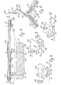
- the thread countersinks consist of two thread push-off plates D1 and D2, which are arranged at a distance from one another above the needle beds B in the direction of movement of the slide and parallel to their planes around an axis of rotation 127 or 227 pivotally mounted on the carriage 5 are.
- the thread pressing plate D1 comes into effect in one running direction F1 of the carriage 5, while the thread pressing plate D2 acts in the other running direction F2 of the carriage 5.
- the two thread pressing plates D1, D2 can be pivoted alternately into a raised, non-contacting position of the thread and into a working position which projects downward in the direction of the needle beds B and depresses the thread into the insertion area of the needles N.
- FIG. 7 shows the state shown in solid lines in FIG. 7, the thread pressing plate D2 is pivoted into its working position, while the thread pressing plate D1 is pivoted up into its rest position.
- the swung-away working position of the thread pull-off plate D1 and the swung-up rest position of the thread pull-off plate D2 are shown in FIG. 7 with dashed lines.
- FIGS. 8 to 11 show the pivoted working position of the thread pressing plate D2.
- the two thread pressing plates D1, D2 are connected to one another with the aid of a hinge plate 28 which is articulated to the two thread pressing plates D1, D2 in 129 and -229.
- This link plate 28 is connected by a link 30 to a shift rod 31 which is parallel to the direction of movement of the slide 5 and which is mounted on the slide 5 so as to be longitudinally displaceable in slide bearings 32.
- the handlebar 30 is articulated in 130 on the joint plate 28 and in 230 on a clamp 33 fastened on the shift rod 31.
- stop collars 34 are provided which cooperate with the plain bearings 32 and limit the longitudinal displacement of the shift rod 31 in both directions.
- the shift rod 31 is held in its two end positions by a spring-loaded detent ball 35 arranged in a slide bearing 32, which engages alternately in two mutually projecting, annular grooves 36, 136 of the shift rod 31.
- the two thread pressing plates D1, D2 are arranged on the carriage 5 of the flat knitting machine at an incline such that their plane includes an angle K with the vertical longitudinal center plane of the needle beds B, as is shown in particular in FIG. 11.
- This angle K is smaller than the angle K 'that each needle bed B forms with the vertical longitudinal center plane of the needle bed pair B-B.
- This thread deflecting edge 37, 137 ends with a pointed or tooth-shaped thread guide nose 38 which projects against the needles N and also somewhat out of the plane of the thread pressing plate D1, D2 in question in the direction of the longitudinal center plane of the two needle beds B.
- the other thread pressing plate Dl has the same operation as described above in the opposite running direction Fl of the carriage 5.
Landscapes
- Engineering & Computer Science (AREA)
- Textile Engineering (AREA)
- Knitting Machines (AREA)
Applications Claiming Priority (2)
| Application Number | Priority Date | Filing Date | Title |
|---|---|---|---|
| IT12521/84A IT1180765B (it) | 1984-05-22 | 1984-05-22 | Macchina rettilinea da maglieria dotata di mezzi che la rendono adatta alla fabbricazione di maglia ad in tarsio senza che i beccucci guidafilo debbano essere sottoposti a movimenti ciclici di abbassamento e di sollevamento |
| IT1252184 | 1984-05-22 |
Publications (1)
| Publication Number | Publication Date |
|---|---|
| EP0164487A1 true EP0164487A1 (fr) | 1985-12-18 |
Family
ID=11141147
Family Applications (1)
| Application Number | Title | Priority Date | Filing Date |
|---|---|---|---|
| EP85100157A Withdrawn EP0164487A1 (fr) | 1984-05-22 | 1985-01-09 | Métier à tricoter rectiligne pour la fabrication de tricot intarsia |
Country Status (2)
| Country | Link |
|---|---|
| EP (1) | EP0164487A1 (fr) |
| IT (1) | IT1180765B (fr) |
Cited By (4)
| Publication number | Priority date | Publication date | Assignee | Title |
|---|---|---|---|---|
| EP0532468A1 (fr) * | 1991-09-11 | 1993-03-17 | TECNIT-Technische Textilien und Systeme GmbH | Elément chauffant électrique |
| EP0679747A1 (fr) * | 1994-04-28 | 1995-11-02 | Shima Seiki Mfg., Ltd. | Procédé pour guider des fils et dispositif pour un métier à tricoter rectiligne |
| EP0754792A1 (fr) * | 1995-07-17 | 1997-01-22 | Tsudakoma Kogyo Kabushiki Kaisha | Procédé pour le tricotage d'un tricot simple |
| DE102011113538B3 (de) * | 2011-09-15 | 2012-08-16 | H. Stoll Gmbh & Co. Kg | Verfahren zur Herstellung eines Gestricks mit Intarsiamuster und Zierstichen |
Citations (3)
| Publication number | Priority date | Publication date | Assignee | Title |
|---|---|---|---|---|
| FR719472A (fr) * | 1931-07-03 | 1932-02-05 | Silbur | Jeteur de fil à fermeture automatique pour machines de bonneterie |
| DE2730306A1 (de) * | 1977-07-05 | 1979-01-25 | H Stoll Gmbh & Co Fa | Verfahren und flachstrickmaschine zur herstellung von fehlerloser intarsienware |
| DE3330317A1 (de) * | 1982-08-24 | 1984-03-01 | Fa. Philipp Mäser, 6850 Dornbirn | Flachstrickmaschine |
-
1984
- 1984-05-22 IT IT12521/84A patent/IT1180765B/it active
-
1985
- 1985-01-09 EP EP85100157A patent/EP0164487A1/fr not_active Withdrawn
Patent Citations (3)
| Publication number | Priority date | Publication date | Assignee | Title |
|---|---|---|---|---|
| FR719472A (fr) * | 1931-07-03 | 1932-02-05 | Silbur | Jeteur de fil à fermeture automatique pour machines de bonneterie |
| DE2730306A1 (de) * | 1977-07-05 | 1979-01-25 | H Stoll Gmbh & Co Fa | Verfahren und flachstrickmaschine zur herstellung von fehlerloser intarsienware |
| DE3330317A1 (de) * | 1982-08-24 | 1984-03-01 | Fa. Philipp Mäser, 6850 Dornbirn | Flachstrickmaschine |
Cited By (5)
| Publication number | Priority date | Publication date | Assignee | Title |
|---|---|---|---|---|
| EP0532468A1 (fr) * | 1991-09-11 | 1993-03-17 | TECNIT-Technische Textilien und Systeme GmbH | Elément chauffant électrique |
| EP0679747A1 (fr) * | 1994-04-28 | 1995-11-02 | Shima Seiki Mfg., Ltd. | Procédé pour guider des fils et dispositif pour un métier à tricoter rectiligne |
| EP0754792A1 (fr) * | 1995-07-17 | 1997-01-22 | Tsudakoma Kogyo Kabushiki Kaisha | Procédé pour le tricotage d'un tricot simple |
| US5819558A (en) * | 1995-07-17 | 1998-10-13 | Tsudakoma Kogyo Kabushiki Kaisha | Method of lowering the yarn height for knitting single knit fabric |
| DE102011113538B3 (de) * | 2011-09-15 | 2012-08-16 | H. Stoll Gmbh & Co. Kg | Verfahren zur Herstellung eines Gestricks mit Intarsiamuster und Zierstichen |
Also Published As
| Publication number | Publication date |
|---|---|
| IT1180765B (it) | 1987-09-23 |
| IT8412521A0 (it) | 1984-05-22 |
Similar Documents
| Publication | Publication Date | Title |
|---|---|---|
| DE4222792B4 (de) | Fadenführerbetätigungsvorrichtung in einer Flachstrickmaschine | |
| DE2910532A1 (de) | Flachstrickmaschine zur herstellung gemusterter strickwaren | |
| DE3343048A1 (de) | Verfahren und vorrichtung zum legen von querschussfaeden fuer eine kettenwirkmaschine | |
| DE3214536C2 (de) | Mascheneinstreichvorrichtung für Flachstrickmaschinen | |
| DE1685151B2 (de) | Fadenzufuehrvorrichtung fuer die nadeln einer tuftingmaschine | |
| CH661539A5 (de) | Flachstrickmaschine. | |
| DE2939639A1 (de) | Flachstrickmaschine | |
| EP0424717A1 (fr) | Machine à tricoter rectiligne | |
| DE1635844B2 (de) | Mustervorrichtung an einer strickmaschine mit zweiteiligen nadeln | |
| DE2730306C2 (de) | Verfahren und Flachstrickmaschine zur Herstellung von Intarsienware | |
| DE3532943C2 (fr) | ||
| DE3813504A1 (de) | Verfahren zum herstellen von intarsien-gestrickstuecken und flachstrickmaschine zur durchfuehrung des verfahrens | |
| DD201710A5 (de) | Schussfadenmagazin mit umkehrschuss fuer eine kettenwirkmaschine | |
| DE102004032270A1 (de) | Strickmaschine mit wenigstens einem Ringelapparat | |
| EP0290008A2 (fr) | Métier à tricoter rectiligne | |
| EP2302118B1 (fr) | Procédé et machine à tricoter destinés à la fabrication de marchandises tricotées selon le motif rayure | |
| DE2531762C2 (de) | Maschenbildende Maschine | |
| DE19505646A1 (de) | Verfahren, Strickmaschine und Platine zur Herstellung von Plüschwaren | |
| DE2541359C2 (de) | Stickmaschine | |
| EP0678127B1 (fr) | Machine a tricoter rectiligne | |
| DE68922764T2 (de) | Vorrichtung zur Halterung des Fadenträgers in einer Flachstrickmaschine. | |
| DE2531705C2 (de) | Strickmaschine | |
| DE2720750C2 (de) | Schloßsystem für Flachstrickmaschinen mit umlaufenden Strickschlitten | |
| EP4326930B1 (fr) | Dispositif et procédé d'alimentation d'une tête de lance d'un métier à tisser en fils de trame | |
| DE3210921C1 (de) | Vorrichtung zum Einziehen von Kettfaeden in bereitgestellte Weblitzen und Lamellen |
Legal Events
| Date | Code | Title | Description |
|---|---|---|---|
| PUAI | Public reference made under article 153(3) epc to a published international application that has entered the european phase |
Free format text: ORIGINAL CODE: 0009012 |
|
| AK | Designated contracting states |
Designated state(s): AT BE CH DE FR GB LI LU NL SE |
|
| STAA | Information on the status of an ep patent application or granted ep patent |
Free format text: STATUS: THE APPLICATION IS DEEMED TO BE WITHDRAWN |
|
| 18D | Application deemed to be withdrawn |
Effective date: 19860819 |
|
| RIN1 | Information on inventor provided before grant (corrected) |
Inventor name: MARTINELLI, CIRO |