EP0164512A1 - Procédé et installation de broyage - Google Patents
Procédé et installation de broyage Download PDFInfo
- Publication number
- EP0164512A1 EP0164512A1 EP85103697A EP85103697A EP0164512A1 EP 0164512 A1 EP0164512 A1 EP 0164512A1 EP 85103697 A EP85103697 A EP 85103697A EP 85103697 A EP85103697 A EP 85103697A EP 0164512 A1 EP0164512 A1 EP 0164512A1
- Authority
- EP
- European Patent Office
- Prior art keywords
- nozzle ring
- air
- mill
- coarse
- constituents
- Prior art date
- Legal status (The legal status is an assumption and is not a legal conclusion. Google has not performed a legal analysis and makes no representation as to the accuracy of the status listed.)
- Granted
Links
- 238000003801 milling Methods 0.000 title claims 3
- 238000000227 grinding Methods 0.000 claims abstract description 27
- 238000000034 method Methods 0.000 claims abstract description 19
- 238000004519 manufacturing process Methods 0.000 claims abstract description 4
- 239000000470 constituent Substances 0.000 claims description 25
- 239000000463 material Substances 0.000 claims description 24
- 238000012216 screening Methods 0.000 claims description 7
- 238000001035 drying Methods 0.000 claims description 3
- 230000003068 static effect Effects 0.000 claims description 3
- 235000021384 green leafy vegetables Nutrition 0.000 claims 1
- 238000009434 installation Methods 0.000 claims 1
- 238000005096 rolling process Methods 0.000 claims 1
- 238000010586 diagram Methods 0.000 description 9
- 238000009423 ventilation Methods 0.000 description 2
- 206010012735 Diarrhoea Diseases 0.000 description 1
- 238000009825 accumulation Methods 0.000 description 1
- 230000007423 decrease Effects 0.000 description 1
- 230000001419 dependent effect Effects 0.000 description 1
- 239000000945 filler Substances 0.000 description 1
- 239000004570 mortar (masonry) Substances 0.000 description 1
- 238000005457 optimization Methods 0.000 description 1
- JTJMJGYZQZDUJJ-UHFFFAOYSA-N phencyclidine Chemical class C1CCCCN1C1(C=2C=CC=CC=2)CCCCC1 JTJMJGYZQZDUJJ-UHFFFAOYSA-N 0.000 description 1
- 230000001376 precipitating effect Effects 0.000 description 1
- 238000007873 sieving Methods 0.000 description 1
- 238000001228 spectrum Methods 0.000 description 1
- 238000003892 spreading Methods 0.000 description 1
- XLYOFNOQVPJJNP-UHFFFAOYSA-N water Substances O XLYOFNOQVPJJNP-UHFFFAOYSA-N 0.000 description 1
Images

Classifications
-
- B—PERFORMING OPERATIONS; TRANSPORTING
- B02—CRUSHING, PULVERISING, OR DISINTEGRATING; PREPARATORY TREATMENT OF GRAIN FOR MILLING
- B02C—CRUSHING, PULVERISING, OR DISINTEGRATING IN GENERAL; MILLING GRAIN
- B02C15/00—Disintegrating by milling members in the form of rollers or balls co-operating with rings or discs
- B02C15/001—Air flow directing means positioned on the periphery of the horizontally rotating milling surface
-
- B—PERFORMING OPERATIONS; TRANSPORTING
- B02—CRUSHING, PULVERISING, OR DISINTEGRATING; PREPARATORY TREATMENT OF GRAIN FOR MILLING
- B02C—CRUSHING, PULVERISING, OR DISINTEGRATING IN GENERAL; MILLING GRAIN
- B02C23/00—Auxiliary methods or auxiliary devices or accessories specially adapted for crushing or disintegrating not provided for in preceding groups or not specially adapted to apparatus covered by a single preceding group
- B02C23/08—Separating or sorting of material, associated with crushing or disintegrating
- B02C23/10—Separating or sorting of material, associated with crushing or disintegrating with separator arranged in discharge path of crushing or disintegrating zone
- B02C23/12—Separating or sorting of material, associated with crushing or disintegrating with separator arranged in discharge path of crushing or disintegrating zone with return of oversize material to crushing or disintegrating zone
-
- B—PERFORMING OPERATIONS; TRANSPORTING
- B02—CRUSHING, PULVERISING, OR DISINTEGRATING; PREPARATORY TREATMENT OF GRAIN FOR MILLING
- B02C—CRUSHING, PULVERISING, OR DISINTEGRATING IN GENERAL; MILLING GRAIN
- B02C23/00—Auxiliary methods or auxiliary devices or accessories specially adapted for crushing or disintegrating not provided for in preceding groups or not specially adapted to apparatus covered by a single preceding group
- B02C23/18—Adding fluid, other than for crushing or disintegrating by fluid energy
- B02C23/24—Passing gas through crushing or disintegrating zone
- B02C23/32—Passing gas through crushing or disintegrating zone with return of oversize material to crushing or disintegrating zone
Definitions
- the invention relates to a grinding method according to the preamble of claim 1 and a plant for performing this method.
- Ring mills are known in particular in the form of roller mills or ball ring mills.
- the grinding tools which are designed as balls or rollers, roll on an annular grinding plate, the grinding pressure being generated by spring force, hydraulic cylinders, by centrifugal force or by the weight of the grinding tools.
- an air stream is fed through a nozzle ring which is arranged in a fixed manner on the outer circumference of the grinding plate and which detects and carries up the fine constituents of the comminuted ground material discharged over the edge of the grinding plate, and carries the coarse constituents downward through the nozzle ring against the air flow fall and, for example, are re-fed to the mill via a mechanical conveyor.
- the invention is therefore based on the object of designing a grinding process of the type required in the preamble of claim 1 (i.e. using an annular mill) in such a way that at least two finished products of different fineness are produced simultaneously in a simple manner.
- At least two finished products of different fineness are produced simultaneously using the same ring mill (roller or ball ring mill), for example a fine finished product with a grain size between 0 and 100 microns and a coarse finished product with a grain size of 0.1 to 2 mm .
- a ring mill roll or ball ring mill
- a fine finished product with a grain size between 0 and 100 microns and a coarse finished product with a grain size of 0.1 to 2 mm .
- the coarse constituents of the ground material which have precipitated through the nozzle ring and are conveyed up by means of a mechanical conveying device are then subjected to a reclassification (sieving or classifying) in the grinding process according to the invention, at least a partial fraction of the coarse constituents being withdrawn as a further finished product and the residual fraction containing the coarsest constituents again the mill can be abandoned.
- a reclassification sieving or classifying
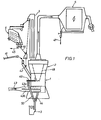
- the grinding system shown in FIG. 1 contains a roller mill 1 with a static classifier 2 arranged above it, a bucket elevator 3, a sieve device 4 and an electrostatic filter 5.
- roller mill 1 The details of the roller mill 1, insofar as they are essential for the understanding of the invention, are first explained in more detail with reference to FIGS. 2 and 3.
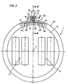
- the roller mill 1 schematically illustrated in FIGS. 1 and 2 contains an annular grinding plate 12 rotating about a vertical axis 11 roll the two pairs of rollers 13, 14.
- a stationary nozzle ring 15 which serves to supply an air flow (see arrow 38 in FIG. 3) which detects the fine constituents of the crushed ground material discharged over the edge of the grinding plate 12 and carries it upwards (Arrow 39), while the coarse constituents of the ground material fall downward against the air flow through the nozzle ring 15 (arrow 40).
- the nozzle ring 15 is divided into several segments, of which the segment 15a is illustrated in detail in FIG.
- the segment 15a of the nozzle ring 15 contains an inner stationary wall part 16, which is connected to the housing 19 of the roller mill 1 via two lateral guide parts 17, 18.
- the stationary inner wall part 16 carries a number of webs 16a which point outwards.
- segment 15a of the nozzle ring 15 contains an outer adjustable wall part 20 which is connected to the push spindle 21 of a pneumatic cylinder 22.
- the thrust spindle 21 is guided radially in slide guides 23, 24.
- the pneumatic cylinder 22 is carried by a flange 25 which is fastened to the housing 19 by means of struts 26, 27.
- the outer wall part 20 of the segment 15a of the nozzle ring 15 is adjustable by means of the spindle 21 of the pneumatic cylinder 22 in the radial direction (double arrow 28), namely between a radially outer position in which the wall part 20 is located near the housing 19 and one Position 20 'indicated by dashed lines, in which the adjustable wall part 20 touches the struts 16a of the stationary inner wall part 16 and in which it limits the clear cross section of the interior 29 of the segment 15a through which the air flows.
- the adjustable wall part 20 of the segment 15a is guided in the region of the ends facing the adjacent segments on parallel guide surfaces 17a, 18a of the guide parts 17, 18.
- a link guide can be provided in the area of these guide surfaces 17a, 18a in order to exclude the risk of the adjustable outer wall part 20 tilting with respect to a horizontal plane.
- the fresh material to be ground from the roller mill 1 is fed in via a conveyor belt 41 and a chute 42.
- the air supply to the roller mill 1 takes place via a line 43 which is divided into sub-lines 43a, 43b and which is connected to a suitable hot air source.
- the coarse constituents of the ground material precipitating through the nozzle ring 15 reach the bucket elevator 3 via a line 44 and are fed by this to the screening device 4.
- At least one partial fraction resulting from the reclassification of the coarse constituents in the screening device 4 (for example the semolina with a grain size between 0 and 4 mm) is drawn off as a finished product (arrow 45), while the residual fraction containing the coarsest constituents (arrow 46) again Mill 1 is fed.
- the fine constituents discharged pneumatically upward from the mill 1 by the air flow are subjected to a sifting in the static sifter 2.
- the fine constituents leaving the classifier 2 with the air stream are separated in the electrostatic filter 5 as a further finished product (arrow 47).
- the grains separated in the classifier 2 can be re-fed to the grinding table 12 of the roller mill 1 in the usual way via the separating funnel 48.
- a selectable portion of this semolina separated in the sifter 2 can be drawn off by a discharge device 49 (for example a screw conveyor) connected to the separating funnel 48 and can also be fed to the bucket elevator 3 via a line 50.
- a discharge device 49 for example a screw conveyor
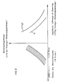
- the diagram according to FIG. 5 explains the relationship between the flow conditions in the nozzle ring and the quantity and fineness of the material falling down through the nozzle ring and conveyed upwards via the bucket elevator.
- the ordinate of the diagram according to FIG. 5 shows the quantity of material in bucket elevator 3 (expressed as a percentage of the quantity of fresh material to be fed into the mill).
- the specific air volume in the nozzle ring is plotted on the abscissa of the right part of the diagram (expressed in m 3 / kg fresh material mill feed quantity).
- the abscissa of the left part of the diagram according to Fig. 5 corresponds to the fineness of the bucket elevator material (expressed in percent residue on a sieve with x mm mesh size). The estate becomes coarser to the left and finer to the right.
- the two curves in the right part of the diagram show the conditions for two different air velocities V 1 and V 2 in the nozzle ring (where V 1 ⁇ V 2 ). It can be seen that as the specific amount of air in the nozzle ring increases, the amount of material in the bucket elevator decreases. If the air speed in the nozzle ring increases while the specific air volume remains the same, the amount of bucket material is also reduced.
- the characteristic curve field in the left part of the diagram is assigned to the two curves in the right part of the diagram. So it can be changed by changing the air speed in the nozzle ring and the specific Air volume achieve different quantities of material in the bucket elevator ("nozzle ring diarrhea") with different grain spectrum.
- the air velocity prevailing in the nozzle ring is primarily influenced by adjusting the outer wall parts 20 of the nozzle ring
- the amount of air supplied to the nozzle ring can be influenced, for example, by adjusting a delivery blower and / or by adjusting adjusting flaps provided in the air feeds to the nozzle ring.
- FIG. 4 shows an embodiment in schematic form, in which four air inlets 60, 61, 62, 63 are provided, to which separately adjustable segments 15'a, 15'b, 15'c and 15'd of a nozzle ring 15 'are assigned.
- These four segments of the nozzle ring 15 ' have, as in the exemplary embodiment already explained with reference to FIGS. 2 and 3, a wall which is adjustable from the outside during operation and which limits and through the clear cross section of the nozzle ring whose adjustment can thus change the flow conditions of the air in the area of the segment concerned.
- the devices for adjusting the cross section of the nozzle ring are likewise not illustrated in FIG.
- adjusting flaps 64 to 67 are provided, which permit a more or less severe throttling of the air flows supplied.
- the air supplied by the air supply lines 60 to 63 is distributed in the manner schematically indicated by the arrows over the circumferential length of the segments 15'a to 15'd of the nozzle ring 15 '.
- the circumferential zones of the grinding plate assigned to the individual segments 15'a to 15'd of the nozzle ring 15 ' can be ventilated differently (with regard to the flow quantities and flow velocities), which is due to the different material accumulation in the individual Zones enables an optimization of the pneumatic material discharge or of the coarse material falling downwards against the air flow through the nozzle ring.
- outer wall parts 20 of the individual segments of the nozzle ring 15 are adjustable by means of pneumatic cylinders 22, within the scope of the invention an adjustment can also be actuated by an electric or hydraulic drive or by means of a handwheel Spindle are provided.
- the number of elements of the nozzle ring 15, each provided with a separate drive, ventilated and adjustable, is adapted to the respective application.
- the nozzle ring can also contain individual non-ventilated segments between ventilated and adjustable segments. For example, a version with eight ventilated, adjustable segments and four non-ventilated segments arranged between them is conceivable.
- the air speed in the nozzle ring is between 30 and 60 m / s, preferably between 35 and 45 m / s in the grinding process according to the invention.
- the amount of coarse constituents falling through the nozzle ring and conveyed up again by the mechanical conveying device is 25 to 200%, preferably 30 to 80%, of the amount of the mill freshly abandoned good.
- the specific amount of air in the nozzle ring is between 0.5 and 4 m 3 / kg, preferably between 0.8 and 2 m 3 / kg, of the material freshly fed to the mill.
- the coarse constituents falling down through the nozzle ring or the partial fractions obtained in the final classification and used as finished product can, if necessary, be subjected to post-drying, for which purpose, for example, a riser dryer, a spreading dryer or a drying drum can be used.
- the flow conditions in the nozzle ring can be changed not only in the manner described by adjusting a wall that limits the cross section of the nozzle ring, by adjusting flaps in the air supply lines and by adjusting a delivery blower, but also, for example, by partially covering the nozzle ring or by partial ventilation or partially different ventilation of the nozzle ring.
- roller mill used in the context of the grinding process according to the invention for the simultaneous production of at least two finished products can, of course, also be used in a conventional manner to produce a single finished product, the devices for influencing The air volume and air speed in the nozzle ring allow the mill to be optimally adapted to the prevailing conditions.
- the specified performance is based on dry product. Effectively, the feed performance due to the water contained - depending on the feed moisture - is higher.
Landscapes
- Engineering & Computer Science (AREA)
- Food Science & Technology (AREA)
- Crushing And Grinding (AREA)
- Disintegrating Or Milling (AREA)
- Air Transport Of Granular Materials (AREA)
- Combined Means For Separation Of Solids (AREA)
Applications Claiming Priority (2)
| Application Number | Priority Date | Filing Date | Title |
|---|---|---|---|
| DE19843418197 DE3418197A1 (de) | 1984-05-16 | 1984-05-16 | Mahlverfahren sowie mahlanlage |
| DE3418197 | 1984-05-16 |
Publications (2)
| Publication Number | Publication Date |
|---|---|
| EP0164512A1 true EP0164512A1 (fr) | 1985-12-18 |
| EP0164512B1 EP0164512B1 (fr) | 1986-12-17 |
Family
ID=6236027
Family Applications (1)
| Application Number | Title | Priority Date | Filing Date |
|---|---|---|---|
| EP85103697A Expired EP0164512B1 (fr) | 1984-05-16 | 1985-03-27 | Procédé et installation de broyage |
Country Status (4)
| Country | Link |
|---|---|
| US (1) | US4927086A (fr) |
| EP (1) | EP0164512B1 (fr) |
| DE (2) | DE3418197A1 (fr) |
| ES (1) | ES8607055A1 (fr) |
Cited By (9)
| Publication number | Priority date | Publication date | Assignee | Title |
|---|---|---|---|---|
| EP0610000A3 (fr) * | 1993-02-04 | 1995-02-01 | Smidth & Co As F L | Procédé de traitement de matières pulvérulentes. |
| FR2746329A1 (fr) * | 1996-03-22 | 1997-09-26 | Fcb | Procede et installation pour la production simultanee et en continu de plusieurs fractions granulometriques d'une matiere minerale |
| EP0979675A1 (fr) | 1998-08-11 | 2000-02-16 | Loesche Gmbh | Procédé et installation de broyage de matières premières |
| CN102861655A (zh) * | 2012-09-23 | 2013-01-09 | 湖南美鑫有机天然植物科技开发有限公司 | 一种精细甘草粉的硬压式研磨方法 |
| CN102861650A (zh) * | 2012-09-20 | 2013-01-09 | 湖南美鑫有机天然植物科技开发有限公司 | 强力硬压式甘草磨粉组合机 |
| WO2013143565A1 (fr) * | 2012-10-17 | 2013-10-03 | Loesche Gmbh | Procédé et dispositif destinés à broyer des matières humides |
| CN107803264A (zh) * | 2017-11-08 | 2018-03-16 | 赵东生 | 一种扰动增强粉碎与表面改性的设备 |
| LU103197B1 (de) * | 2023-09-21 | 2025-03-21 | Thyssenkrupp AG | Vertikalrollenmühle |
| WO2025061554A1 (fr) | 2023-09-21 | 2025-03-27 | thyssenkrupp Polysius GmbH | Laminoir centrifuge vertical |
Families Citing this family (10)
| Publication number | Priority date | Publication date | Assignee | Title |
|---|---|---|---|---|
| DE3801229A1 (de) * | 1988-01-18 | 1989-07-27 | Krupp Polysius Ag | Mahlverfahren sowie mahlanlage |
| DE4002867C1 (fr) * | 1990-02-01 | 1991-08-29 | Evt Energie- Und Verfahrenstechnik Gmbh, 7000 Stuttgart, De | |
| DE4124416A1 (de) * | 1991-07-23 | 1993-01-28 | Krupp Polysius Ag | Einrichtung und verfahren zur zerkleinerung von mahlgut unterschiedlicher koernung |
| US5251826A (en) * | 1992-03-13 | 1993-10-12 | Pennsylvania Crusher Corporation | Tumbling media mill and control system |
| US5667149A (en) * | 1995-07-03 | 1997-09-16 | Foster Wheeler Energy Corporation | Solids pulverizer mill and process utilizing interactive air port nozzles |
| US6213415B1 (en) | 1999-09-13 | 2001-04-10 | W.R. Grace & Co.-Conn. | Process for improving grinding of cement clinker in mills employing rollers |
| FI4856U1 (fi) * | 1999-12-08 | 2001-03-12 | Roxon Oy | Sovitelma liikkuvassa murskauslaitteessa |
| DE102011014592A1 (de) * | 2011-03-21 | 2012-09-27 | Loesche Gmbh | Wälzmühle |
| DE102014014945A1 (de) * | 2014-10-09 | 2016-04-14 | Micro Impact Mill Limited | Vorrichtung und Verfahren zum Erzzerkleinern mit einer hydraulischen Federeinrichtung |
| WO2018016104A1 (fr) * | 2016-07-21 | 2018-01-25 | 株式会社Ihi | Broyeur à rouleaux vertical |
Citations (1)
| Publication number | Priority date | Publication date | Assignee | Title |
|---|---|---|---|---|
| CH435940A (de) * | 1964-02-27 | 1967-05-15 | Georg Claes Fa | Anlage zum Mahlen eines Rohstoffes für die Zementindustrie |
Family Cites Families (10)
| Publication number | Priority date | Publication date | Assignee | Title |
|---|---|---|---|---|
| US1523881A (en) * | 1921-03-17 | 1925-01-20 | Blanton Kreutzberg Company | Pulverizing apparatus |
| DE719987C (de) * | 1938-10-08 | 1942-04-24 | Carbo Union Ind Mij Nv | Federrollenmuehle |
| DE818721C (de) * | 1949-05-11 | 1952-08-04 | Ernst Guenter Loesche | Federrollenmuehle |
| AT189039B (de) * | 1954-05-18 | 1957-02-25 | Combustion Eng | Federrollenmühle |
| US3491954A (en) * | 1966-03-22 | 1970-01-27 | Riley Stoker Corp | Air flow regulator for a pulverizer |
| US3951347A (en) * | 1972-09-21 | 1976-04-20 | Polysius Ag | Apparatus for crushing material containing particles that are hard to pulverize |
| DD106953A1 (fr) * | 1973-10-09 | 1974-07-12 | ||
| DD127023B1 (de) * | 1976-07-28 | 1982-03-31 | Karl Hoeffl | Mahlanlage zur feinzerkleinerung von mineralien |
| US4240586A (en) * | 1978-12-21 | 1980-12-23 | Evans Robert F | Method and apparatus for crushing and classifying particulate material |
| GB2118457B (en) * | 1982-04-13 | 1985-05-22 | Smidth & Co As F L | Edge runner mills |
-
1984
- 1984-05-16 DE DE19843418197 patent/DE3418197A1/de not_active Withdrawn
-
1985
- 1985-03-27 DE DE8585103697T patent/DE3560030D1/de not_active Expired
- 1985-03-27 EP EP85103697A patent/EP0164512B1/fr not_active Expired
- 1985-05-14 ES ES543135A patent/ES8607055A1/es not_active Expired
- 1985-05-14 US US06/733,945 patent/US4927086A/en not_active Expired - Fee Related
Patent Citations (1)
| Publication number | Priority date | Publication date | Assignee | Title |
|---|---|---|---|---|
| CH435940A (de) * | 1964-02-27 | 1967-05-15 | Georg Claes Fa | Anlage zum Mahlen eines Rohstoffes für die Zementindustrie |
Cited By (12)
| Publication number | Priority date | Publication date | Assignee | Title |
|---|---|---|---|---|
| EP0610000A3 (fr) * | 1993-02-04 | 1995-02-01 | Smidth & Co As F L | Procédé de traitement de matières pulvérulentes. |
| FR2746329A1 (fr) * | 1996-03-22 | 1997-09-26 | Fcb | Procede et installation pour la production simultanee et en continu de plusieurs fractions granulometriques d'une matiere minerale |
| WO1997035665A1 (fr) * | 1996-03-22 | 1997-10-02 | Fcb | Procede et installation pour la production simultanee et en continu de plusieurs fractions granulometriques d'une matiere minerale |
| US6042032A (en) * | 1996-03-22 | 2000-03-28 | Fcb Societe Anonyme | Method and apparatus for simultaneously and continuously producing a plurality of size fractions of a mineral material |
| EP0979675A1 (fr) | 1998-08-11 | 2000-02-16 | Loesche Gmbh | Procédé et installation de broyage de matières premières |
| CN102861650A (zh) * | 2012-09-20 | 2013-01-09 | 湖南美鑫有机天然植物科技开发有限公司 | 强力硬压式甘草磨粉组合机 |
| CN102861655A (zh) * | 2012-09-23 | 2013-01-09 | 湖南美鑫有机天然植物科技开发有限公司 | 一种精细甘草粉的硬压式研磨方法 |
| WO2013143565A1 (fr) * | 2012-10-17 | 2013-10-03 | Loesche Gmbh | Procédé et dispositif destinés à broyer des matières humides |
| CN107803264A (zh) * | 2017-11-08 | 2018-03-16 | 赵东生 | 一种扰动增强粉碎与表面改性的设备 |
| CN107803264B (zh) * | 2017-11-08 | 2019-06-18 | 赵东生 | 一种扰动增强粉碎与表面改性的设备 |
| LU103197B1 (de) * | 2023-09-21 | 2025-03-21 | Thyssenkrupp AG | Vertikalrollenmühle |
| WO2025061554A1 (fr) | 2023-09-21 | 2025-03-27 | thyssenkrupp Polysius GmbH | Laminoir centrifuge vertical |
Also Published As
| Publication number | Publication date |
|---|---|
| US4927086A (en) | 1990-05-22 |
| DE3418197A1 (de) | 1985-11-21 |
| ES8607055A1 (es) | 1986-06-01 |
| EP0164512B1 (fr) | 1986-12-17 |
| DE3560030D1 (en) | 1987-01-29 |
| ES543135A0 (es) | 1986-06-01 |
Similar Documents
| Publication | Publication Date | Title |
|---|---|---|
| EP0164512B1 (fr) | Procédé et installation de broyage | |
| EP0525423B1 (fr) | Dispositif et procédé de broyage de matériau avec une granulométrie variable | |
| EP0603481B1 (fr) | Procédé et installation pour le broyage de matière à moudre | |
| EP0325770B1 (fr) | Procédé et installation de broyage | |
| EP0460490B1 (fr) | Séparateur pneumatique | |
| DE9007802U1 (de) | Umlaufmahlanlage | |
| EP0173065A2 (fr) | Broyeur à cylindres | |
| EP0292739B1 (fr) | Procédé et installation pour le broyage de matière à broyer | |
| EP3209423A1 (fr) | Installation de broyage pour pulvériser une matière à broyer et procédé de pulvérisation de matière à broyer | |
| DE2100235C3 (de) | Anlage zum Trockenvermahlen von vorgebrochenen Rohmaterialien in einem gechlossenen Kreislaufsystem | |
| EP0406591B1 (fr) | Procédé et installation de broyage de matière à broyer | |
| WO2016124627A1 (fr) | Installation de broyage à circulation munie de deux dispositifs de broyage et procédé permettant de faire fonctionner l'installation de broyage à circulation | |
| WO2001021328A1 (fr) | Procede et separateur a air servant a separer de la matiere de chargement fractionnee | |
| WO2007054191A1 (fr) | Broyeur a rouleaux | |
| EP0338231B1 (fr) | Installation de broyage | |
| EP0165429B1 (fr) | Procédé pour l'entraînement d'une installation de broyage et dispositif pour l'exécution de ce procédé | |
| EP0237641B1 (fr) | Installation pour le broyage de matière à broyer fragile | |
| DE3538991A1 (de) | Verfahren zur feinstzerkleinerung von mineralischen stoffen und vorrichtung zur durchfuehrung des verfahrens | |
| DE3710602C2 (fr) | ||
| EP0791407A2 (fr) | Séparateur pneumatique | |
| DE19526040A1 (de) | Verfahren und Anlage zur Zerkleinerung von Mahlgut | |
| DE4307230A1 (de) | Verfahren und Anlage zur Gutbettzerkleinerung von sprödem Mahlgut | |
| DE1199107B (de) | Verfahren zum Mahlen von Weizen und Anlage zur Durchfuehrung des Verfahrens | |
| EP3368222B1 (fr) | Séparateur à cascades raccordé pneumatiquement et système de broyage à circulation doté de séparateurs à cascades raccordés pneumatiquement | |
| DE2617274C2 (de) | Mahltrocknungsanlage |
Legal Events
| Date | Code | Title | Description |
|---|---|---|---|
| PUAI | Public reference made under article 153(3) epc to a published international application that has entered the european phase |
Free format text: ORIGINAL CODE: 0009012 |
|
| 17P | Request for examination filed |
Effective date: 19851011 |
|
| AK | Designated contracting states |
Designated state(s): DE FR GB IT |
|
| 17Q | First examination report despatched |
Effective date: 19860610 |
|
| GRAA | (expected) grant |
Free format text: ORIGINAL CODE: 0009210 |
|
| AK | Designated contracting states |
Kind code of ref document: B1 Designated state(s): DE FR GB IT |
|
| REF | Corresponds to: |
Ref document number: 3560030 Country of ref document: DE Date of ref document: 19870129 |
|
| ET | Fr: translation filed | ||
| ITF | It: translation for a ep patent filed | ||
| PLBI | Opposition filed |
Free format text: ORIGINAL CODE: 0009260 |
|
| 26 | Opposition filed |
Opponent name: KLOECKNER-HUMBOLDT-DEUTZ AG, KOELN C/O KHD HUMBOLD Effective date: 19870912 |
|
| PGFP | Annual fee paid to national office [announced via postgrant information from national office to epo] |
Ref country code: FR Payment date: 19900202 Year of fee payment: 6 |
|
| PGFP | Annual fee paid to national office [announced via postgrant information from national office to epo] |
Ref country code: GB Payment date: 19900228 Year of fee payment: 6 |
|
| ITTA | It: last paid annual fee | ||
| PGFP | Annual fee paid to national office [announced via postgrant information from national office to epo] |
Ref country code: DE Payment date: 19900411 Year of fee payment: 6 |
|
| PLBN | Opposition rejected |
Free format text: ORIGINAL CODE: 0009273 |
|
| STAA | Information on the status of an ep patent application or granted ep patent |
Free format text: STATUS: OPPOSITION REJECTED |
|
| 27O | Opposition rejected |
Effective date: 19881014 |
|
| PG25 | Lapsed in a contracting state [announced via postgrant information from national office to epo] |
Ref country code: GB Effective date: 19910327 |
|
| GBPC | Gb: european patent ceased through non-payment of renewal fee | ||
| PG25 | Lapsed in a contracting state [announced via postgrant information from national office to epo] |
Ref country code: FR Effective date: 19911129 |
|
| PG25 | Lapsed in a contracting state [announced via postgrant information from national office to epo] |
Ref country code: DE Effective date: 19920101 |
|
| REG | Reference to a national code |
Ref country code: FR Ref legal event code: ST |
|
| APAH | Appeal reference modified |
Free format text: ORIGINAL CODE: EPIDOSCREFNO |