EP0164529A1 - Vanne a voies multiples - Google Patents
Vanne a voies multiples Download PDFInfo
- Publication number
- EP0164529A1 EP0164529A1 EP85104657A EP85104657A EP0164529A1 EP 0164529 A1 EP0164529 A1 EP 0164529A1 EP 85104657 A EP85104657 A EP 85104657A EP 85104657 A EP85104657 A EP 85104657A EP 0164529 A1 EP0164529 A1 EP 0164529A1
- Authority
- EP
- European Patent Office
- Prior art keywords
- bore
- guide
- annular groove
- webs
- control valve
- Prior art date
- Legal status (The legal status is an assumption and is not a legal conclusion. Google has not performed a legal analysis and makes no representation as to the accuracy of the status listed.)
- Granted
Links
- 239000000853 adhesive Substances 0.000 claims abstract description 9
- 230000001070 adhesive effect Effects 0.000 claims abstract description 9
- 238000007789 sealing Methods 0.000 claims description 4
- 238000009423 ventilation Methods 0.000 claims 2
- 238000000034 method Methods 0.000 claims 1
- 238000011161 development Methods 0.000 description 1
- 230000018109 developmental process Effects 0.000 description 1
Images
Classifications
-
- F—MECHANICAL ENGINEERING; LIGHTING; HEATING; WEAPONS; BLASTING
- F16—ENGINEERING ELEMENTS AND UNITS; GENERAL MEASURES FOR PRODUCING AND MAINTAINING EFFECTIVE FUNCTIONING OF MACHINES OR INSTALLATIONS; THERMAL INSULATION IN GENERAL
- F16K—VALVES; TAPS; COCKS; ACTUATING-FLOATS; DEVICES FOR VENTING OR AERATING
- F16K11/00—Multiple-way valves, e.g. mixing valves; Pipe fittings incorporating such valves
- F16K11/02—Multiple-way valves, e.g. mixing valves; Pipe fittings incorporating such valves with all movable sealing faces moving as one unit
- F16K11/06—Multiple-way valves, e.g. mixing valves; Pipe fittings incorporating such valves with all movable sealing faces moving as one unit comprising only sliding valves, i.e. sliding closure elements
- F16K11/065—Multiple-way valves, e.g. mixing valves; Pipe fittings incorporating such valves with all movable sealing faces moving as one unit comprising only sliding valves, i.e. sliding closure elements with linearly sliding closure members
- F16K11/07—Multiple-way valves, e.g. mixing valves; Pipe fittings incorporating such valves with all movable sealing faces moving as one unit comprising only sliding valves, i.e. sliding closure elements with linearly sliding closure members with cylindrical slides
- F16K11/0712—Multiple-way valves, e.g. mixing valves; Pipe fittings incorporating such valves with all movable sealing faces moving as one unit comprising only sliding valves, i.e. sliding closure elements with linearly sliding closure members with cylindrical slides comprising particular spool-valve sealing means
-
- F—MECHANICAL ENGINEERING; LIGHTING; HEATING; WEAPONS; BLASTING
- F16—ENGINEERING ELEMENTS AND UNITS; GENERAL MEASURES FOR PRODUCING AND MAINTAINING EFFECTIVE FUNCTIONING OF MACHINES OR INSTALLATIONS; THERMAL INSULATION IN GENERAL
- F16K—VALVES; TAPS; COCKS; ACTUATING-FLOATS; DEVICES FOR VENTING OR AERATING
- F16K27/00—Construction of housing; Use of materials therefor
- F16K27/04—Construction of housing; Use of materials therefor of sliding valves
- F16K27/041—Construction of housing; Use of materials therefor of sliding valves cylindrical slide valves
Definitions
- the invention is based on a directional valve according to the type of the main claim.
- the control slide is guided in bores in guide disks. These have a smooth surface on the outer circumference and are glued into the valve housing. This makes it difficult to dose the required amount of adhesive. Excess adhesive can get on the running surfaces of the control spool or on the sealing rings arranged in the guide discs. The sliding ability of the control spool is affected.
- the directional control valve according to the invention with the characterizing features of the main claim has the advantage that the guide disks are firmly arranged in the slide bore before the adhesive is bonded and while the adhesive is curing. This shortens the assembly time.
- the amount of adhesive can be precisely metered, whereby the strength is not reduced by air bubbles becomes.
- the piston running surfaces and the sealing rings are free of adhesive.
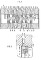
- FIG. 1 shows a longitudinal section through a directional valve and FIG. 2 shows a detail.
- a central, continuous stepped bore 12 is formed in the housing 10 of a 5/2-way valve 11, which is used as a compressed air valve. This is offset six times from each of the two end faces 13, 14 of the housing 10. It has a central section 15 with the smallest diameter and on both sides six sections 16 to 21 with increasing diameters. In section 15, an annular groove is formed, which serves as an inlet chamber 23. On the shoulder 2h formed between sections 15 and 16 and on every second shoulder to the respective end face 13 or respectively. 14 following shoulder 25, 26 of the stepped bore 12 are on both sides of the section 15 guide discs 27, 28, 29. The spaces formed between the guide disks 27, 28, 29 in the region of the sections 17, 19 serve as control chambers 31, 32 and as consumer chambers 33, 34.
- Each guide disk 27 to 29 has an annular groove 36 on its outer circumference, as shown in more detail in FIG.
Landscapes
- Engineering & Computer Science (AREA)
- General Engineering & Computer Science (AREA)
- Mechanical Engineering (AREA)
- Multiple-Way Valves (AREA)
- Sliding Valves (AREA)
Applications Claiming Priority (2)
| Application Number | Priority Date | Filing Date | Title |
|---|---|---|---|
| DE19843420127 DE3420127A1 (de) | 1984-05-30 | 1984-05-30 | Wegeventil |
| DE3420127 | 1984-05-30 |
Publications (2)
| Publication Number | Publication Date |
|---|---|
| EP0164529A1 true EP0164529A1 (fr) | 1985-12-18 |
| EP0164529B1 EP0164529B1 (fr) | 1987-11-04 |
Family
ID=6237190
Family Applications (1)
| Application Number | Title | Priority Date | Filing Date |
|---|---|---|---|
| EP85104657A Expired EP0164529B1 (fr) | 1984-05-30 | 1985-04-17 | Vanne a voies multiples |
Country Status (2)
| Country | Link |
|---|---|
| EP (1) | EP0164529B1 (fr) |
| DE (2) | DE3420127A1 (fr) |
Cited By (3)
| Publication number | Priority date | Publication date | Assignee | Title |
|---|---|---|---|---|
| EP0579379A1 (fr) * | 1992-06-16 | 1994-01-19 | Aqualisa Products Limited | Garniture pour fluides |
| EP0931963A3 (fr) * | 1998-01-22 | 2000-12-20 | Robert Bosch Gmbh | Distributeur |
| EP1950423A1 (fr) * | 2007-01-29 | 2008-07-30 | Peugeot Citroen Automobiles SA | Distributeur hydralique à pilotage proportionnel et procédé de montage d'un tel distributeur |
Families Citing this family (3)
| Publication number | Priority date | Publication date | Assignee | Title |
|---|---|---|---|---|
| DE4314312A1 (de) * | 1993-04-30 | 1994-11-03 | Teves Gmbh Alfred | Elektrohydraulische Druckregelvorrichtung |
| DE19802311A1 (de) | 1998-01-22 | 1999-08-05 | Bosch Gmbh Robert | Wegeventil |
| DE19813981C2 (de) * | 1998-03-28 | 2001-12-06 | Bosch Gmbh Robert | Schiebergesteuertes Wegeventil |
Citations (4)
| Publication number | Priority date | Publication date | Assignee | Title |
|---|---|---|---|---|
| US3246665A (en) * | 1963-04-24 | 1966-04-19 | Fessler Machine Company | Lubricated three way fluid valve |
| FR2035282A5 (fr) * | 1969-02-10 | 1970-12-18 | Norgren Co C A | |
| FR2072357A5 (fr) * | 1970-11-23 | 1971-09-24 | Garcia Jean Claude | |
| FR2329884A1 (fr) * | 1975-10-30 | 1977-05-27 | Kloeckner Humboldt Deutz Ag | Element pour l'assemblage de deux pieces metalliques |
-
1984
- 1984-05-30 DE DE19843420127 patent/DE3420127A1/de not_active Withdrawn
-
1985
- 1985-04-17 EP EP85104657A patent/EP0164529B1/fr not_active Expired
- 1985-04-17 DE DE8585104657T patent/DE3560921D1/de not_active Expired
Patent Citations (4)
| Publication number | Priority date | Publication date | Assignee | Title |
|---|---|---|---|---|
| US3246665A (en) * | 1963-04-24 | 1966-04-19 | Fessler Machine Company | Lubricated three way fluid valve |
| FR2035282A5 (fr) * | 1969-02-10 | 1970-12-18 | Norgren Co C A | |
| FR2072357A5 (fr) * | 1970-11-23 | 1971-09-24 | Garcia Jean Claude | |
| FR2329884A1 (fr) * | 1975-10-30 | 1977-05-27 | Kloeckner Humboldt Deutz Ag | Element pour l'assemblage de deux pieces metalliques |
Cited By (4)
| Publication number | Priority date | Publication date | Assignee | Title |
|---|---|---|---|---|
| EP0579379A1 (fr) * | 1992-06-16 | 1994-01-19 | Aqualisa Products Limited | Garniture pour fluides |
| EP0931963A3 (fr) * | 1998-01-22 | 2000-12-20 | Robert Bosch Gmbh | Distributeur |
| EP1950423A1 (fr) * | 2007-01-29 | 2008-07-30 | Peugeot Citroen Automobiles SA | Distributeur hydralique à pilotage proportionnel et procédé de montage d'un tel distributeur |
| FR2911931A1 (fr) * | 2007-01-29 | 2008-08-01 | Peugeot Citroen Automobiles Sa | Distributeur hydraulique a pilotage proportionnel et procede de montage d'un tel distributeur |
Also Published As
| Publication number | Publication date |
|---|---|
| DE3560921D1 (en) | 1987-12-10 |
| EP0164529B1 (fr) | 1987-11-04 |
| DE3420127A1 (de) | 1985-12-05 |
Similar Documents
| Publication | Publication Date | Title |
|---|---|---|
| DE19960305A1 (de) | Ventilelement und Verfahren zum Herstellen desselben | |
| EP0164529B1 (fr) | Vanne a voies multiples | |
| DE1204478B (de) | Hahn mit Abdichtung durch Profilring | |
| EP0195178B1 (fr) | Vanne d'écoulement et d'arrêt | |
| DE4418524C2 (de) | Vorgesteuertes 3-Wege-Druckminderventil | |
| DE3540997C2 (fr) | ||
| DE2311720C2 (de) | Ventil für Kolbenverdichter | |
| EP0108951B1 (fr) | Vanne à voies multiples | |
| DE3910381A1 (de) | Sammelanschlussplatte | |
| EP0152620B1 (fr) | Soupape directionnelle | |
| DE3210209A1 (de) | Kraftstoff-einspritzduese fuer brennkraftmaschinen | |
| DE2628371A1 (de) | Druck-regulierventil hoechster feinfuehligkeit und genauigkeit mit ausgeglichener hochdruckseite | |
| DE3410017A1 (de) | Farbwechselventil | |
| DE3838684C1 (en) | Valve, particularly for compressors or vacuum pumps | |
| DE1296909B (de) | Mehrwegeventil | |
| EP0389776B1 (fr) | Corps de raccordement en forme de bloc | |
| EP0151330A2 (fr) | Soupape à voies multiples | |
| DE2903902A1 (de) | Ventil fuer unter druck stehende gasfoermige oder fluessige medien | |
| DE3018482A1 (de) | Absperrmembran | |
| DE2005287B2 (de) | Funktionswahlvorrichtung für ein Hydraulik- oder Pneumatikventil | |
| DE2251244B2 (de) | Vorrichtung zum Versprühen eines flüssigen Kühlmediums zur Abkühlung von wärmebehandeltem Draht in kontinuierlichem Durchlauf | |
| DE3016003A1 (de) | Ringfoermiges plattenventil | |
| DE1550383C2 (de) | Dreiwegeventil mit elastischen Verschlußteilen | |
| DE1000199B (de) | Rueckschlagventil als Fluessigkeitsabscheider | |
| EP0204031A1 (fr) | Soupape à plusieurs voies |
Legal Events
| Date | Code | Title | Description |
|---|---|---|---|
| PUAI | Public reference made under article 153(3) epc to a published international application that has entered the european phase |
Free format text: ORIGINAL CODE: 0009012 |
|
| 17P | Request for examination filed |
Effective date: 19850417 |
|
| AK | Designated contracting states |
Designated state(s): DE FR GB IT |
|
| 17Q | First examination report despatched |
Effective date: 19860716 |
|
| GRAA | (expected) grant |
Free format text: ORIGINAL CODE: 0009210 |
|
| AK | Designated contracting states |
Kind code of ref document: B1 Designated state(s): DE FR GB IT |
|
| REF | Corresponds to: |
Ref document number: 3560921 Country of ref document: DE Date of ref document: 19871210 |
|
| ET | Fr: translation filed | ||
| GBT | Gb: translation of ep patent filed (gb section 77(6)(a)/1977) | ||
| ITF | It: translation for a ep patent filed | ||
| PLBE | No opposition filed within time limit |
Free format text: ORIGINAL CODE: 0009261 |
|
| STAA | Information on the status of an ep patent application or granted ep patent |
Free format text: STATUS: NO OPPOSITION FILED WITHIN TIME LIMIT |
|
| 26N | No opposition filed | ||
| ITTA | It: last paid annual fee | ||
| PGFP | Annual fee paid to national office [announced via postgrant information from national office to epo] |
Ref country code: FR Payment date: 19930429 Year of fee payment: 9 |
|
| PGFP | Annual fee paid to national office [announced via postgrant information from national office to epo] |
Ref country code: DE Payment date: 19930624 Year of fee payment: 9 |
|
| PGFP | Annual fee paid to national office [announced via postgrant information from national office to epo] |
Ref country code: GB Payment date: 19940407 Year of fee payment: 10 |
|
| PG25 | Lapsed in a contracting state [announced via postgrant information from national office to epo] |
Ref country code: FR Effective date: 19941229 |
|
| PG25 | Lapsed in a contracting state [announced via postgrant information from national office to epo] |
Ref country code: DE Effective date: 19950103 |
|
| REG | Reference to a national code |
Ref country code: FR Ref legal event code: ST |
|
| PG25 | Lapsed in a contracting state [announced via postgrant information from national office to epo] |
Ref country code: GB Effective date: 19950417 |
|
| GBPC | Gb: european patent ceased through non-payment of renewal fee |
Effective date: 19950417 |