EP0164644A2 - Gerät zum Auftragen kosmetischer Flüssigkeiten - Google Patents
Gerät zum Auftragen kosmetischer Flüssigkeiten Download PDFInfo
- Publication number
- EP0164644A2 EP0164644A2 EP85106564A EP85106564A EP0164644A2 EP 0164644 A2 EP0164644 A2 EP 0164644A2 EP 85106564 A EP85106564 A EP 85106564A EP 85106564 A EP85106564 A EP 85106564A EP 0164644 A2 EP0164644 A2 EP 0164644A2
- Authority
- EP
- European Patent Office
- Prior art keywords
- ball
- housing
- capillary material
- liquid
- bearing seat
- Prior art date
- Legal status (The legal status is an assumption and is not a legal conclusion. Google has not performed a legal analysis and makes no representation as to the accuracy of the status listed.)
- Withdrawn
Links
- 239000007788 liquid Substances 0.000 title claims abstract description 42
- 239000002537 cosmetic Substances 0.000 title claims abstract description 10
- 239000000463 material Substances 0.000 claims abstract description 17
- 239000002304 perfume Substances 0.000 claims abstract description 5
- 239000012528 membrane Substances 0.000 description 6
- 238000007789 sealing Methods 0.000 description 4
- 238000005096 rolling process Methods 0.000 description 3
- 239000004809 Teflon Substances 0.000 description 1
- 229920006362 Teflon® Polymers 0.000 description 1
- 239000000356 contaminant Substances 0.000 description 1
- 238000011109 contamination Methods 0.000 description 1
- 239000002781 deodorant agent Substances 0.000 description 1
- 230000005489 elastic deformation Effects 0.000 description 1
- 239000002657 fibrous material Substances 0.000 description 1
- 239000006260 foam Substances 0.000 description 1
- 239000004519 grease Substances 0.000 description 1
- 239000012535 impurity Substances 0.000 description 1
- 239000002184 metal Substances 0.000 description 1
- 238000000034 method Methods 0.000 description 1
- 239000004033 plastic Substances 0.000 description 1
- 230000036316 preload Effects 0.000 description 1
- 239000011347 resin Substances 0.000 description 1
- 229920005989 resin Polymers 0.000 description 1
- 229910001220 stainless steel Inorganic materials 0.000 description 1
- 239000010935 stainless steel Substances 0.000 description 1
- 239000012209 synthetic fiber Substances 0.000 description 1
- 229920002994 synthetic fiber Polymers 0.000 description 1
Images
Classifications
-
- A—HUMAN NECESSITIES
- A45—HAND OR TRAVELLING ARTICLES
- A45D—HAIRDRESSING OR SHAVING EQUIPMENT; EQUIPMENT FOR COSMETICS OR COSMETIC TREATMENTS, e.g. FOR MANICURING OR PEDICURING
- A45D34/00—Containers or accessories specially adapted for handling liquid toiletry or cosmetic substances, e.g. perfumes
- A45D34/04—Appliances specially adapted for applying liquid, e.g. using roller or ball
- A45D34/041—Appliances specially adapted for applying liquid, e.g. using roller or ball using a roller, a disc or a ball
Definitions
- the invention relates to a device for applying cosmetic liquids, in particular perfume, with a housing for receiving a liquid supply and with a rotatably mounted ball in a bearing seat at the application end of the housing, which protrudes with a part of its surface from the application end.
- the need to rotatably support the ball in order to be able to effect the application process allows the use of only relatively viscous liquids in the known devices of this type, if a reliable seal should be guaranteed when not in use.
- the known devices are less suitable for low-viscosity cosmetic liquids, such as perfume, because the bearing seat of the ball does not provide sufficient tightness against them, so that leakage must be feared in the lying and unused state.
- devices for applying cosmetic liquids which do not belong to the above-mentioned genus are also known, in which the application surface is formed by a fixed membrane made of tissue or foam permeable to the liquid, below which a spring-loaded valve with a valve body which can be actuated through the membrane is arranged. By pressing the membrane against the skin, the valve is opened so that liquid can escape, penetrate the membrane and be applied to the skin.
- the arrangement of the valve means that these devices are leak-proof, but they are applied through rubbing contact with the skin ', as a result of which impurities in the skin, grease and the like are deposited on the outer surface of the membrane over time. This is perceived as unsanitary.
- a common disadvantage of the two known devices discussed above is that the amount of liquid applied to the skin depends on the amount of liquid supplied to the ball bearing seat or the back of the membrane, which in turn depends on the position of the device (more or less tilting). fluctuates.
- the invention is therefore based on the object of providing a leak-proof device of the type mentioned which can also be used for low-viscosity cosmetic liquids, in particular for perfume, and which allows the liquid to be applied evenly to the skin regardless of the position of the device.
- this object is achieved in that the ball is in contact with at least part of its surface facing the housing interior with a body made of capillary material connected to the liquid supply.
- the cosmetic liquid is not supplied directly to the spherical surface facing the interior of the housing, but via the capillary material of the body in contact with the sphere, i.e. -so controlled according to the eligibility of this body. Liquid is only sucked out of the body and fed back from the liquid supply due to its capillary action, as long as liquid is released on the skin by a rolling movement of the ball. If no liquid is dispensed, there is essentially no liquid supply through the body made of capillary material. As a result, the sealability of the ball in its bearing seat is sufficient even when using relatively low-viscosity cosmetic liquids.
- Another significant advantage is that the contact of the ball with the body made of capillary material means that any contaminants absorbed by the skin are constantly stripped off the body and remain inside the device. As a result, the spherical surface itself always remains clean and hygienic.
- the body made of capillary material forms part of the bearing seat of the ball and expediently rests against the ball under elastic prestress.
- This system can either be caused by the fact that the body is slidably arranged and under a spring load or due to the fact that the body held immovably in the application end of the housing consists of an elastically deformable material and is installed in deformation against the ball.
- the body either has a spherical bearing recess for the ball or forms it on account of its elastic deformability, so that the ball is sufficiently wetted with liquid for a strong application.
- the elastic preload of the ball causes it to be pressed against the sealing lip of the bearing seat on the application side, which further improves the seal when not in use.
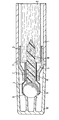
- a wick 2 made of capillary material is accommodated as a liquid reservoir.
- the open end of the housing 1 is closed by a guide cap 3 fitted with a tight fit, which tapers conically towards the front and holds a holder 4 made of thin stainless steel sheet.
- the guide cap 3 has on its inside a number of radially inwardly projecting ribs 5, the rear-facing end faces serve as a stop for the wick 2 and the radially inward-facing longitudinal sides form a continuation of the receiving bore 6 for the socket 4.
- the socket 4 sits with a neck-like part-7 sealed in the receiving bore 6 and widens outside of this for receiving a ball 8, preferably made of Teflon.
- the ball 8 is held in a bearing seat, which is formed on the one hand by a bent circumferential sealing lip 9 of the socket 4 and on the other hand by the front end face of a body 10 made of capillary material.
- the body 10 is held in the neck part 7 of the holder 4 and, with its rear end, projects a piece immovably into the wick 2. It consists of an elastically deformable fiber material, for example synthetic fibers, which are bound together by means of a resin, and presses the ball 8 against the sealing lip 9 due to an elastic deformation. As a result, the front end face of the body 10 rests in the form of a dome on the back of the ball 8 .
- the guide cap 3 has a circumferential collar 11 with which it is supported on the end face of the housing 1 and which also serves to support a closure cap 12 of the device.
- the outwardly widened part of the holder 4 allows the mounting of a ball 8 which is large in relation to the diameter of the housing and whose diameter is, for example, 1 cm. With a releasable fastening of the socket 4 in the guide cap 3, it is possible, after the consumption of the liquid contained in the wick 2. amount to refill and use the device again.
- the part of the ball 8 protruding beyond the lip 9 is placed on the skin and the ball is rotated by rubbing. Since the ball 8 is supplied with liquid on the back by the body 10 made of capillary material, it remains constantly wetted during the rolling process, so that through the contact liquid can be released onto the skin. In the unused state, ie when no liquid is removed from the spherical end face of the body 10, no liquid flows through this body either. Possibly. liquid accumulating behind the bearing seat over time is prevented from escaping by the pressure of the ball 8 on the sealing lip 9.
- Liquid on the surface of the ball which for some reason has not been applied to the skin and is returned to the inside of the bearing seat, is wiped off, along with any contamination that may be present, on the edge of the spherical end face of the body 10, so that it always remains on the ball only that amount of liquid is present which corresponds to the supply through the body 10.
Landscapes
- Closures For Containers (AREA)
Abstract
Description
- Die Erfindung betrifft ein Gerät zum Auftragen kosmetischer Flüssigkeiten, insbesondere Parfüm, mit einem Gehäuse zur Aufnahme eines Flüssigkeitsvorrates und mit einer in einem Lagersitz am Auftragende des Gehäuses drehbar gelagerten Kugel, die mit einem Teil ihrer Fläche aus dem Auftragende herausragt.
- Geräte mit den vorstehend angegebenen konstruktiven Merkmalen sind zum Auftragen von beispielsweise Deodorant-Flüssigkeiten bereits bekannt. Die als Auftragfläche auf die Haut dienende Kugel ist bei diesen bekannten Geräten in einer Ausnehmung am Auftragende des Gehäuses unter einer gewissen Vorspannung so gehalten, daß sie einerseits an einer einen Teil des Lagersitzes bildenden Lippe am Auftragende dichtend anliegt und dadurch ein Austreten der Flüssigkeit in unbenutztem Zustand verhindert, andererseits jedoch durch den Reibkontakt mit der Haut noch drehbar ist. Durch ein Kippen des Geräts gelangt Flüssigkeit in den Lagersitz der Kugel, so daß diese auf ihrer dem Gehäuseinneren zugewendeten Fläche davon benetzt wird und im Zuge des Anrollvorganges Flüssigkeit auf die Haut abgibt.
- Die Notwendigkeit, die Kugel drehbar zu lagern, um den Auftragvorgang bewirken zu können, erlaubt bei den bekannten Geräten dieser Art die-Anwendung lediglich verhältnismässig viskoser Flüssigkeiten, wenn eine sichere Abdichtung im unbenutzten Zustand gewährleistet sein soll. Für dünnflüssige Kosmetikflüssigkeiten, z.B. Parfüm, sind die bekannten Geräte weniger geeignet, weil gegenüber diesen der Lagersitz der Kugel keine ausreichende Dichtheit gewährt, so daß im liegenden und unbenutzten Zustand ein Auslaufen befürchtet werden muß.
- Es sind weiterhin auch nicht zu der vorstehend behandelten Gattung zählende Geräte zum Auftragen kosmetischer Flüssigkeiten bekannt, bei denen die Auftragfläche durch eine für die Flüssigkeit durchlässige feststehende Membran aus Gewebe oder Schaumstoff gebildet ist, unter der ein federbelastetes Ventil mit einem durch die Membran hindurch betätigbaren Ventilkörper angeordnet ist. Durch das Andrücken der Membran an die Haut wird das Ventil geöffnet, so daß Flüssigkeit austreten, die Membran durchsetzen und auf die Haut aufgetragen werden kann. Durch die Anordnung des Ventils sind diese Geräte zwar auslaufsicher, jedoch erfolgt das Auftragen durch reibenden Kontakt mit der Haut', wodurch Unreinheiten der Haut, Fett und dgl. im Laufe der Zeit auf der Außenfläche der Membran abgelagert werden. Das wird als unhygienisch empfunden. Ein gemeinsamer Nachteil der beiden vorstehend besprochenen bekannten Geräte besteht darin, daß die auf die Haut aufgetragene Flüssigkeitsmenge von der dem Lagersitz der Kugel bzw. der Rückseite der Membran zugeführten Flüssigkeitsmenge abhängt, die wiederum je nach der Haltung des Geräts (mehr oder weniger starkes Kippen) schwankt.
- Der Erfindung liegt daher die Aufgabe zugrunde, ein auslaufsicheres Gerät der eingangs genannten Gattung zu schaffen, das auch für dünnflüssige Kosmetikflüssigkeiten, insbesondere für Parfüm, brauchbar ist und unabhängig von der Haltung des Geräts ein gleichmässiges Auftragen der Flüssigkeit auf die Haut gestattet.
- Erfindungsgemäß wird diese Aufgabe dadurch gelöst, daß die Kugel zumindest mit einem Teil ihrer dem Gehäuseinneren zugewendeten Fläche mit einem mit dem Flüssigkeitsvorrat verbundenen Körper aus kapillarem Material in Kontakt steht.
- Bei dem erfindungsgemässen Gerät erfolgt die Zuführung der kosmetischen Flüssigkeit zu der dem Gehäuseinneren zugewendeten Kugelfläche nicht direkt, sondern über das kapillare Material des an der Kugel anliegenden Körpers, d.h. -also gesteuert entsprechend der Förderfähigkeit dieses Körpers. Flüssigkeit wird aus dem Körper nur abgesaugt und durch dessen Kapillarwirkung von dem Flüssigkeitsvorrat wieder zugeführt, solange durch eine Abrollbewegung der Kugel auf der Haut Flüssigkeit abgegeben wird. Erfolgt keine Flüssigkeitsabgabe, so unterbleibt auch im wesentlichen eine Flüssigkeitszufuhr durch den Körper aus kapillarem Material. Folglich reicht die Dichtfähigkeit der Kugel in ihrem Lagersitz auch bei Anwendung verhältnismässig dünnflüssiger Kosmetikflüssigkeiten aus.
- Ein weiterer wesentlicher Vorteil besteht darin, daß durch den Kontakt der Kugel mit dem Körper aus kapillarem Material evtl. von der Haut aufgenommene Verunreinigungen ständig an dem Körper abgestreift werden und im Inneren des Geräts verbleiben. Die Kugelfläche selbst bleibt dadurch immer sauber und hygienisch.
- Nach einer besonders vorteilhaften Weiterbildung der Erfindung ist vorgesehen; daß der Körper aus kapillarem Material einen Teil des Lagersitzes der Kugel bildet und zweckmässigerweise unter elastischer Vorspannung an der Kugel anliegt. Diese Anlage kann entweder dadurch bewirkt werden, daß der Körper verschiebbar angeordnet ist und unter einer Federbelastung steht oder dadurch, daß der unverschieblich im Auftragende des Gehäuses gehaltene Körper aus einem elastisch verformbaren Werkstoff besteht und unter Verformung in Anlage an die Kugel eingebaut ist. Der Körper weist bei dieser Ausgestaltung entweder eine kalottenförmige Lagerausnehmung für die Kugel auf oder bildet diese aufgrund sei-ner elastischen Verformbarkeit, so-daß hierdurch die Kugel ausreichend für einen kräftigen Auftrag mit Flüssigkeit benetzt ist. Darüber hinaus bewirkt die elastische Vorspannung der Kugel deren Andrücken an die auftragseitige Dichtlippe des Lagersitzes, wodurch die Abdichtung im unbenutzten Zustand noch verbessert wird.
- Ein Ausführungsbeispiel der Erfindung ist nachfolgend anhand der beiliegenden Zeichnung näher erläutert. Die Zeichnung zeigt in stark vergrössertem Maßstab einen Längsschnitt durch das auftragseitige Ende des (abgebrochen dargestellten) Gehäuses des Geräts.
- In dem aus Kunststoff oder Metall bestehenden Gehäuse 1, das vorzugsweise die Abmessungen eines herkömmlichen Füllfederhalters oder Schreibstiftes hat, ist als Flüssigkeitsspeicher ein aus kapillarem Werkstoff bestehender Docht 2 aufgenommen. Das offene Ende des Gehäuses 1 ist durch eine mit strengem Sitz eingepasste Führungskappe 3 verschlossen, die sich nach vorne kegelförmig verjüngt und eine aus dünnem Edelstahlblech bestehende Fassung 4 haltert. Die Führungskappe 3 weist auf ihrer Innenseite eine Anzahl von radial nach innen vorspringenden Rippen 5 auf, deren nach hinten zeigende Stirnseiten als Anschlag für den Docht 2 dienen und deren radial nach innen weisende Längsseiten eine Fortsetzung der Aufnahmebohrung 6 für die Fassung 4 bilden.
- Die Fassung 4 sitzt mit einem halsartigen Teil-7 abgedichtet in der Aufnahmebohrung 6 und erweitert sich außerhalb dieser zur Aufnahme einer vorzugsweise aus Teflon bestehenden Kugel 8. Die Kugel 8 ist in einem Lagersitz gehalten, der einerseits durch eine eingebogene umlaufende Dichtlippe 9 der Fassung 4 und andererseits durch die vordere Stirnfläche eines Körpers 10 aus kapillarem Material gebildet ist. Der Körper 10 ist in dem Halsteil 7 der Fassung 4 gehalten und ragt mit seinem hinteren Ende ein Stück unverschieblich in den Docht 2 hinein. Er besteht aus einem elastisch verformbaren Fasermaterial, z.B. aus Kunstfasern, die mittels eines Harzes aneinandergebunden sind, und drückt auf grund einer elastischen Verformung die Kugel 8 gegen die Dichtlippe 9. Hierdurch liegt die vordere Stirnfläche des Körpers 10 kalottenförmig an der Rückseite der Kugel 8 an.
- Die Führungskappe 3 weist einen umlaufenden Bund 11 auf, mit dem sie sich an der Stirnseite des Gehäuses 1 abstützt und der zugleich zur Abstützung einer Verschlußkappe 12 des Geräts dient.
- Der nach außen erweiterte Teil der Fassung 4 erlaubt die Lagerung einer im Verhältnis zu dem-Durchmesser des Gehäuses groß bemessenen Kugel 8, deren Durchmesser beispielsweise 1 cm beträgt. Bei einer lösbaren Befestigung der Fassung 4 in der Führungskappe 3 ist es möglich, nach dem Verbrauch der in dem Docht 2 enthaltenen Flüssigkeits- . menge diesen erneut zu füllen und das Gerät wieder zu verwenden.
- Bei der Benutzung des Geräts wird der über die Lippe 9 hinausragende Teil der Kugel 8 auf die Haut aufgesetzt und die Kugel durch Anreiben in Drehung versetzt. Da die Kugel 8 auf der Rückseite durch den Körper 10 aus kapillarem Material Flüssigkeit zugefördert erhält, bleibt sie während des Abrollvorganges ständig benetzt, so daß durch den Kontakt mit der Haut Flüssigkeit auf diese abgegeben werden kann. In unbenutztem Zustand, d.h. wenn keine Flüssigkeit aus der kalottenförmigen Stirnseite des Körpers 10 entfernt wird, strömt durch diesen Körper auch keine Flüssigkeit nach. Evtl. sich hinter dem Lagersitz im Laufe der Zeit ansammelnde Flüssigkeit wird durch den Andruck der Kugel 8 an die Dichtlippe 9 an einem Austreten gehindert. Flüssigkeit auf der Kugeloberfläche, die aus irgendeinem Grund nicht auf die Haut aufgetragen worden ist und wieder in das Innere des Lagersitzes zurückgeführt wird, wird zusammen mit evtl. vorhandenen Verunreinigungen an der Kante der kalottenförmigen Stirnfläche des Körpers 10 abgestreift, so daß auf der Kugel stets nur diejenige Flüssigkeitsmenge vorhanden ist, die der Zuführung durch den Körper 10 entspricht.
Claims (5)
Applications Claiming Priority (2)
| Application Number | Priority Date | Filing Date | Title |
|---|---|---|---|
| DE19848418176 DE8418176U1 (de) | 1984-06-15 | 1984-06-15 | Gerät zum Auftragen kosmetischer Flüssigkeiten |
| DE8418176U | 1984-06-15 |
Publications (2)
| Publication Number | Publication Date |
|---|---|
| EP0164644A2 true EP0164644A2 (de) | 1985-12-18 |
| EP0164644A3 EP0164644A3 (de) | 1986-11-26 |
Family
ID=6767929
Family Applications (1)
| Application Number | Title | Priority Date | Filing Date |
|---|---|---|---|
| EP85106564A Withdrawn EP0164644A3 (de) | 1984-06-15 | 1985-05-29 | Gerät zum Auftragen kosmetischer Flüssigkeiten |
Country Status (2)
| Country | Link |
|---|---|
| EP (1) | EP0164644A3 (de) |
| DE (1) | DE8418176U1 (de) |
Cited By (4)
| Publication number | Priority date | Publication date | Assignee | Title |
|---|---|---|---|---|
| EP0249042A1 (de) * | 1986-05-13 | 1987-12-16 | Edding AG | Auftragsgerät |
| GB2255052A (en) * | 1991-04-23 | 1992-10-28 | Ahrens Hans Joachim | Ball applicator for cosmetics |
| WO1995013046A1 (en) * | 1993-11-08 | 1995-05-18 | The Gillette Company | Antiperspirants and method of applying antiperspirant using a shaped article |
| GB2304644A (en) * | 1995-08-30 | 1997-03-26 | Tsubota Pearl Co Ltd | Ball type perfume applicator |
Families Citing this family (2)
| Publication number | Priority date | Publication date | Assignee | Title |
|---|---|---|---|---|
| DE19635262C2 (de) * | 1996-08-30 | 1998-07-23 | Jungnickel Jens Uwe | Auftragsvorrichtung für Toilettenwasser, Parfüm und dergleichen hochviskose und flüchtige Flüssigkeiten |
| DE10156531B4 (de) * | 2001-11-14 | 2007-04-12 | Dehn, Michael C. | Deoroller |
Family Cites Families (10)
| Publication number | Priority date | Publication date | Assignee | Title |
|---|---|---|---|---|
| GB638709A (en) * | 1947-05-12 | 1950-06-14 | George Augustus Davis | Improvements in devices for applying liquids to surfaces |
| FR948655A (fr) * | 1947-06-30 | 1949-08-08 | Appareil pour l'application des fards | |
| FR58429E (fr) * | 1947-12-31 | 1953-11-27 | Bâton de touche de parfum | |
| FR1007270A (fr) * | 1948-03-13 | 1952-05-05 | Perfectionnements apportés aux tubes pour l'application du rouge à lèvres liquide | |
| US2654108A (en) * | 1948-03-17 | 1953-10-06 | Lee J Scelsi | Revolvable ball type liquid applicator |
| DE1461620A1 (de) * | 1964-09-01 | 1969-04-17 | Georg Linz | Schreibspitze fuer Kugelschreiber,insbesondere Tintenkugelschreiber |
| GB1237043A (en) * | 1969-02-18 | 1971-06-30 | Le Foyer Formerly Le Foyer Et | Writing device |
| NL7513107A (en) * | 1975-11-07 | 1977-05-10 | Edward Bok Burgemeester Amersf | Fountain pen ink control system - has flexible reservoir compressed by fitting cap in place |
| DE2934695C2 (de) * | 1979-08-28 | 1984-08-09 | Fa. J.S. Staedtler, 8500 Nürnberg | Schreibgerät, sowie Verfahren zur Herstellung einer sicheren Verbindung von Schreibgeräteteilen miteinander |
| DE3302528A1 (de) * | 1982-02-04 | 1983-08-04 | Scribex S.A., Agno | Mine fuer kugelschreiber |
-
1984
- 1984-06-15 DE DE19848418176 patent/DE8418176U1/de not_active Expired
-
1985
- 1985-05-29 EP EP85106564A patent/EP0164644A3/de not_active Withdrawn
Cited By (6)
| Publication number | Priority date | Publication date | Assignee | Title |
|---|---|---|---|---|
| EP0249042A1 (de) * | 1986-05-13 | 1987-12-16 | Edding AG | Auftragsgerät |
| GB2255052A (en) * | 1991-04-23 | 1992-10-28 | Ahrens Hans Joachim | Ball applicator for cosmetics |
| WO1995013046A1 (en) * | 1993-11-08 | 1995-05-18 | The Gillette Company | Antiperspirants and method of applying antiperspirant using a shaped article |
| US5843413A (en) * | 1993-11-08 | 1998-12-01 | The Gillette Company | Antiperspirants and method of applying antiperspirant using a shaped article |
| GB2304644A (en) * | 1995-08-30 | 1997-03-26 | Tsubota Pearl Co Ltd | Ball type perfume applicator |
| GB2304644B (en) * | 1995-08-30 | 1999-04-28 | Tsubota Pearl Co Ltd | Applicator |
Also Published As
| Publication number | Publication date |
|---|---|
| DE8418176U1 (de) | 1984-10-04 |
| EP0164644A3 (de) | 1986-11-26 |
Similar Documents
| Publication | Publication Date | Title |
|---|---|---|
| DE4015152A1 (de) | Geraet zum auftrag von fluessigkeiten | |
| DE3941380A1 (de) | Geraet zum auftrag von fluessigkeiten | |
| WO2008028619A1 (de) | Abgabevorrichtung | |
| EP0969972B1 (de) | Flüssigkeitsregler zur versorgung eines verbrauchers mit flüssigkeit aus einem flüssigkeitsvorrat | |
| DE69421534T2 (de) | Kugelauftragvorrichtung | |
| DE2208111A1 (de) | Schreibgeraet mit einer schreibspitze aus poroesem oder kapillarem werkstoff | |
| DE3346805A1 (de) | Make-up-buerste | |
| DE2309738C3 (de) | Markier- oder Schreibgerät | |
| DE69607980T2 (de) | Spenderkappe für flüssigkeitsbehälter | |
| DE8418176U1 (de) | Gerät zum Auftragen kosmetischer Flüssigkeiten | |
| EP1830965A1 (de) | Vorrichtung zum dosierten ausbringen eines mediums | |
| DE3402614A1 (de) | Dosier- und auftragvorrichtung fuer fluessigkeiten | |
| DE3009587A1 (de) | Koerperpflegegeraet zum auftragen von koerperpflegemittel | |
| DE102010045653A1 (de) | Ölspender | |
| EP0072772A2 (de) | An einem Schreibgerät angebrachter Befeuchter für Briefmarken | |
| DE4138148A1 (de) | Schreibspitzenkoerper fuer ein geraet zum auftragen von fluessigkeiten | |
| DE2152512A1 (de) | Zahnbuerstenfuellhalter | |
| DE958995C (de) | Fluessigkeitsspender, insbesondere Leimspender, in Taschenformat | |
| DE841277C (de) | Anfeuchtgeraet fuer Klebeflaechen | |
| DE652877C (de) | Auftragevorrichtung fuer Faerbfluessigkeiten | |
| Högel | Schweißen, Prüfen, Handhaben im Verbund. | |
| DE2264488A1 (de) | Schreibgeraet mit einer schreibspitze aus poroesem oder kapillarem werkstoff | |
| DE1267136B (de) | Fuellvorrichtung fuer Fuellfederhalter | |
| CH269816A (de) | Schreibeinrichtung. | |
| DE20220567U1 (de) | Spender für fließfähige Medien |
Legal Events
| Date | Code | Title | Description |
|---|---|---|---|
| PUAI | Public reference made under article 153(3) epc to a published international application that has entered the european phase |
Free format text: ORIGINAL CODE: 0009012 |
|
| 17P | Request for examination filed |
Effective date: 19850921 |
|
| AK | Designated contracting states |
Designated state(s): DE FR GB IT |
|
| ITCL | It: translation for ep claims filed |
Representative=s name: STUDIO TORTA SOCIETA' SEMPLICE |
|
| EL | Fr: translation of claims filed | ||
| PUAL | Search report despatched |
Free format text: ORIGINAL CODE: 0009013 |
|
| AK | Designated contracting states |
Kind code of ref document: A3 Designated state(s): DE FR GB IT |
|
| STAA | Information on the status of an ep patent application or granted ep patent |
Free format text: STATUS: THE APPLICATION IS DEEMED TO BE WITHDRAWN |
|
| 18D | Application deemed to be withdrawn |
Effective date: 19870527 |
|
| RIN1 | Information on inventor provided before grant (corrected) |
Inventor name: MOECK, GERHARD |