EP0164762A2 - Récipient pour produits aromatiques - Google Patents
Récipient pour produits aromatiques Download PDFInfo
- Publication number
- EP0164762A2 EP0164762A2 EP85108350A EP85108350A EP0164762A2 EP 0164762 A2 EP0164762 A2 EP 0164762A2 EP 85108350 A EP85108350 A EP 85108350A EP 85108350 A EP85108350 A EP 85108350A EP 0164762 A2 EP0164762 A2 EP 0164762A2
- Authority
- EP
- European Patent Office
- Prior art keywords
- devices
- lid
- rotating ring
- box according
- ring
- Prior art date
- Legal status (The legal status is an assumption and is not a legal conclusion. Google has not performed a legal analysis and makes no representation as to the accuracy of the status listed.)
- Granted
Links
Images
Classifications
-
- B—PERFORMING OPERATIONS; TRANSPORTING
- B65—CONVEYING; PACKING; STORING; HANDLING THIN OR FILAMENTARY MATERIAL
- B65D—CONTAINERS FOR STORAGE OR TRANSPORT OF ARTICLES OR MATERIALS, e.g. BAGS, BARRELS, BOTTLES, BOXES, CANS, CARTONS, CRATES, DRUMS, JARS, TANKS, HOPPERS, FORWARDING CONTAINERS; ACCESSORIES, CLOSURES, OR FITTINGS THEREFOR; PACKAGING ELEMENTS; PACKAGES
- B65D83/00—Containers or packages with special means for dispensing contents
- B65D83/76—Containers or packages with special means for dispensing contents for dispensing fluent contents by means of a piston
- B65D83/768—Containers or packages with special means for dispensing contents for dispensing fluent contents by means of a piston the piston or movable bottom being pulled upwards to dispense the contents
Definitions
- the invention relates to a can for aromatic substances.
- Cans of this type are used to store substances with a strong aroma, such as coffee, tea, tobacco or spices.
- a strong aroma such as coffee, tea, tobacco or spices.
- the air space above the filled substances increases with the gradual emptying. The result of this is that the air circulation caused by temperature differences between the interior and the outside environment in the air space above this filling material increases considerably and the aroma therefore suffers considerably.
- EP-A-0 135 974 describes a can in which a stamp, which is attached to the lid, is pressed onto the filling material from above.
- DE-GM 72 32 726 shows a can, in which a lid also rests on the contents. The Contents are removed from the area of the can base. The lid slides further down when the product is removed.
- the present invention has for its object to provide a can for flavored substances in which, regardless of the level of the fill level, the aroma is completely preserved even on the top layer of the filling material, in which the filling material can be removed conveniently and easily in a conventional manner and which is inexpensive to manufacture.
- a can for aromatic substances with a height-displaceable device for minimizing the air volume located above the filling material, in which the device is a base carrying the filling material.
- This box ensures that the air volume above the product can always be kept as small as possible. This prevents turbulence in the air and the resulting removal of aromas.
- the bottom of the can is height-adjustable by turning the lid.
- pulling devices can be provided which are attached to a rotating ring which is rotatably mounted in the plane perpendicular to the moving device of the floor, the tangential pull applied by the pulling devices being deflectable in one pull in the direction of movement of the floor by a deflection device.
- a preferred embodiment of the box has at least three pulling devices, which all have the same length) and can be attached to the rotating ring with an axial offset, the respective azimuthal distances between the fastening points of the pulling devices on the rotating ring and the associated deflection devices for compensation of the axial offset are of different sizes.
- the base can be moved upwards by means of upper rotating and pulling devices as well as by means of lower rotating and pulling devices.
- the base has a sealing device, which is preferably directed upwards and, when loaded from above, bears against the inner wall of the can.
- the inside diameter of the space intended for receiving the filling material tapers at the upper end in order to bring the upper layers of the filling material into the middle when the bottom moves upward and thus prevent the filling material from sticking in the corners.
- the lid of the box can be used to operate the rotating ring.
- the cover preferably has at least two driver devices which interact with corresponding counterparts in the rotating ring and at the same time define the angular position of the cover in relation to the rotating ring.
- the driver device and the corresponding counterparts can be designed such that the rotary ring can only be rotated in one direction by the cover.
- the driver devices can have overload safeguards that respond before a torque that overloads the pulling devices is applied to the rotating ring through the cover.
- the can has a fill level indicator, which in particular consists of a pointer connected to the lid and a mark made on the outside of the can.
- the angular and axial position of the rotating ring can be fixed by suitable fixing devices that interact with counterparts in the can wall.
- the lower end of the can can have an air outlet opening in order to facilitate the downward movement of the movable base, which is necessary before the can is refilled.
- the can can have guide grooves or channels for the pulling devices.
- the pulling devices are designed as plastic threads, each having a first cross-sectional enlargement at both ends and a second cross-sectional enlargement at the end of the first cross-sectional enlargement.
- the lid of the can has a surface that extends as far as the filling material. This surface can be formed by a filler or a pot-shaped recess in the lid.
- the lid has an edge which projects beyond the outside of the can and is provided with slots and is held on the can by spring force. This allows the lid on the can to be easily turned and removed with a simple pull.
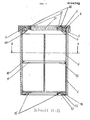
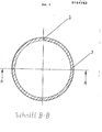
- the box is a hollow cylinder open at both ends, in which a bottom 10 is located.
- This base can preferably be designed as a piston.
- This bottom carries an upwardly facing sealing lip 11, which bears against the can wall 1.
- the sealing lip 11 is pressed against the can wall 1 by its own elasticity and by the weight of the filling material.
- the floor is moved by means of traction devices 3, which are guided in grooves 2 in the can wall 1.
- the traction devices are, for example, plastic threads which have a first cross-sectional enlargement at both ends and a second cross-sectional enlargement at the end of the first cross-section enlargement. This allows them to be easily attached to the floor during manufacture, which has a device for this attachment, for example a projection, in which there is a slot, the width of which corresponds to the diameter of the central part of the plastic cord and a bore is located at the lower end thereof whose diameter is equal to the first cross-sectional enlargement of the plastic filament. With this device, the plastic thread can be easily fixed.
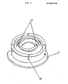
- a fixed ring 4 in which a movable rotary ring 5 is rotatably mounted in the plane perpendicular to the direction of movement of the base.
- the traction devices 3 are guided through slots' in a fixed ring 4 and are attached to the rotating ring 5.
- the fixed ring 4 thus fulfills the function of a deflection device.
- the pulling devices 3 are wound onto this rotating ring 5.
- the fixed ring 4 serving as a deflection device, the tangential pull, to which the pulling device is exposed due to the rotation of the rotating ring 5, is converted into an axial pull, and thus the floor moves axially.
- a cover ring 6 is provided so that the pulling devices 3 cannot inadvertently move away from the rotating ring 5.
- the fixed ring 4 has a bevel on its side facing the base 10, as a result of which the inside diameter of the space intended for receiving the filling material is reduced. As a result, the filling material at the upper end of the can is pressed inwards during the upward movement of the base and no filling material can become lodged in the upper edge of the can.
- lower pulling devices are provided which are similar to the upper pulling devices.
- a cover ring 14 is identical to the upper cover ring 6, a lower rotary ring 13 is identical to the upper rotary ring 5 and a lower fixed ring 12, which also fulfills the function of a deflection device, corresponds to the upper fixed ring 4, only the bevel on the Bottom-facing side is not necessary here.
- the fixed ring 4, 12 can be fixed in its angular and axial position relative to the can wall 1 by means of suitable fixing devices, for example grooves and projections.
- Fastening points 17 of the traction devices are offset in the azimuthal direction on the rotary ring 5 so that they compensate for the axial offset. If, for example, the bottom 10 is in its lowermost position, then the fastening point 17 of the pulling device 3, which is attached to the top of the rotating ring 5, lies opposite the associated slot in the fixed ring 4. The fastening points 17 of the other pulling devices 3, are arranged further down on the rotating ring 5, are so far removed in the direction of rotation from the associated slot in the fixed ring 4 that they compensate for the axial offset.
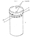
- the rotating ring 5 can be moved with the aid of a can lid 7.
- the can lid has driver devices 16 which cooperate with associated counterparts 15 in the rotating ring 5.
- These counterparts 15 can be designed as projections with steep front flanks and gently sloping back flanks, so that the rotating ring can only be rotated in one direction by the cover 7. If the lid is rotated in the other direction, the driver devices 16 find no resistance in the lid, but slide upwards on the gently sloping flank of the projections.
- the driver devices 16 in the cover advantageously have overload protection devices which respond before a moment is applied to the rotary ring 5, 13 by the cover 7, which overstresses the pulling devices 3.
- the angular position of the cover with respect to the rotary ring 5, 13 can be defined by suitable measures, for example in which two projections 15 are provided in the rotary ring 5, 13, which lie on two separate circular rings.
- Each height of the base 10 in the can corresponds to a specific angular position of the rotating ring 5. Since the cover 7 assumes a defined position relative to the rotating ring 5, the position of the cover 7 provides information about the height of the base 10. This is used for a level indicator in which one on the The pointer 7 located on the lid 7 points to a mark 19 on the outside of the can, from which the fill level of the can can be read directly.
- the lid 7 can have a cup-shaped depression or a filler 21, the lower surface of which extends to the filling material. This results in an additional reduction in the air volume above the product.
- the lid 7 has an edge 8 projecting over the outer wall of the can. This edge has slots 22. As a result, the individual sections of the lid edge 8, which are formed by the slots 22, can be provided with a certain spring force, which hold the lid 7 on the can. The lid 7 can then be easily rotated and removed by a simple pull.
- the lower end face of the can which is essentially formed from the lower fixed ring 12, has an opening through which the air can escape when the base 10 is moved downwards.
- the upward movement of the base which takes place only after the filling material has been removed, is generally so slow that the excess air can escape through the small number of leaks between the lid 7 and the can. Is the can completely empty, i.e. once the bottom 10 has reached its uppermost position, to refill the can it is necessary to return the bottom to its lowest position.
- the lid 7 is placed on the underside of the can. By simply turning the cover 7, which cooperates with the projections 15 of the lower rotating ring 13, the bottom 10 is pulled downwards. Since the sealing lip 11 of the base 10 is directed upwards, it is not damaged when the base 10 is actuated.
- a second sealing ring can also be attached below the base 10.
Landscapes
- Engineering & Computer Science (AREA)
- Mechanical Engineering (AREA)
- Closures For Containers (AREA)
- Organic Low-Molecular-Weight Compounds And Preparation Thereof (AREA)
- Disinfection, Sterilisation Or Deodorisation Of Air (AREA)
- Packages (AREA)
Priority Applications (1)
| Application Number | Priority Date | Filing Date | Title |
|---|---|---|---|
| AT85108350T ATE51200T1 (de) | 1984-09-14 | 1985-07-05 | Dose fuer aromatische stoffe. |
Applications Claiming Priority (2)
| Application Number | Priority Date | Filing Date | Title |
|---|---|---|---|
| DE8427192U | 1984-09-14 | ||
| DE19848427192U DE8427192U1 (de) | 1984-09-14 | 1984-09-14 | Aromahaltende gebrauchsdose fuer kaffee, tee, kakao, gewuerze, tabak, medikamente usw. |
Publications (3)
| Publication Number | Publication Date |
|---|---|
| EP0164762A2 true EP0164762A2 (fr) | 1985-12-18 |
| EP0164762A3 EP0164762A3 (en) | 1987-05-13 |
| EP0164762B1 EP0164762B1 (fr) | 1990-03-21 |
Family
ID=6770724
Family Applications (1)
| Application Number | Title | Priority Date | Filing Date |
|---|---|---|---|
| EP85108350A Expired - Lifetime EP0164762B1 (fr) | 1984-09-14 | 1985-07-05 | Récipient pour produits aromatiques |
Country Status (4)
| Country | Link |
|---|---|
| US (1) | US4646919A (fr) |
| EP (1) | EP0164762B1 (fr) |
| AT (1) | ATE51200T1 (fr) |
| DE (2) | DE8427192U1 (fr) |
Cited By (1)
| Publication number | Priority date | Publication date | Assignee | Title |
|---|---|---|---|---|
| NL1010050C2 (nl) * | 1998-09-10 | 2000-03-13 | Sara Lee De Nv | Samenstel omvattende een houder en een met een poedervormig materiaal gevuld pak dat in de houder is opgenomen. |
Families Citing this family (3)
| Publication number | Priority date | Publication date | Assignee | Title |
|---|---|---|---|---|
| US4938377A (en) * | 1989-11-02 | 1990-07-03 | Jarvis Robert B | Device for preserving aroma and flavor of potable liquid including a buoyant lid |
| DE4316716C1 (de) * | 1993-05-19 | 1994-07-28 | Berno Zimmer | Vorratsbehälter für Kaffeepulver |
| CN109969562B (zh) * | 2019-04-02 | 2020-05-26 | 陈艳 | 一种妇产科临床用胎心仪 |
Family Cites Families (14)
| Publication number | Priority date | Publication date | Assignee | Title |
|---|---|---|---|---|
| US654031A (en) * | 1900-04-03 | 1900-07-17 | Willard Putnam Smith | Tobacco-holder. |
| US1181611A (en) * | 1915-02-09 | 1916-05-02 | Raymel C Purcell | Tobacco-can. |
| GB257474A (en) * | 1925-11-14 | 1926-09-02 | William Henry Gregory Geake | Improvements in semi-fluid dispensing device |
| US1945805A (en) * | 1929-11-14 | 1934-02-06 | Briggs & Stratton Corp | Cigar, cigarette, or the like receptacle |
| US1945141A (en) * | 1931-12-17 | 1934-01-30 | Roger R Fenska | Receptacle |
| US2190163A (en) * | 1938-09-14 | 1940-02-13 | Handy Containers Inc | Container |
| US2281251A (en) * | 1940-02-21 | 1942-04-28 | Ernest S Mitchell | Container |
| US2346087A (en) * | 1942-10-09 | 1944-04-04 | Eleftheria Sevastopulos | Container for tobacco, cigarettes, and pipe cleaners, and the like articles |
| FR1002929A (fr) * | 1946-11-04 | 1952-03-12 | Récipient distributeur de pâtes | |
| US2599071A (en) * | 1950-09-19 | 1952-06-03 | Schwarz John | Dispensing container for mustard, ketchup, and the like, having a slidable piston with hollow stem |
| US3027052A (en) * | 1958-07-14 | 1962-03-27 | Leonard L Marraffino | Dial operated dispenser |
| FR1307952A (fr) * | 1961-09-12 | 1962-11-03 | Récipient distributeur à fond mobile | |
| DE7232726U (de) * | 1972-09-05 | 1972-11-30 | Sauter F | Behälter mit Spender insbesondere für aromatische Stoffe |
| EP0135974A3 (fr) * | 1983-09-26 | 1986-06-11 | Thomassen & Drijver-Verblifa N.V. | Procédé pour le stockage étanche à l'air d'un produit non-gazeux dans un récipient, ce produit étant destiné à être enlevé par portions de ce récipient; dispositif pour la mise en oeuvre de ce procédé |
-
1984
- 1984-09-14 DE DE19848427192U patent/DE8427192U1/de not_active Expired
-
1985
- 1985-07-05 DE DE8585108350T patent/DE3576674D1/de not_active Expired - Fee Related
- 1985-07-05 EP EP85108350A patent/EP0164762B1/fr not_active Expired - Lifetime
- 1985-07-05 AT AT85108350T patent/ATE51200T1/de not_active IP Right Cessation
- 1985-09-11 US US06/774,937 patent/US4646919A/en not_active Expired - Fee Related
Cited By (1)
| Publication number | Priority date | Publication date | Assignee | Title |
|---|---|---|---|---|
| NL1010050C2 (nl) * | 1998-09-10 | 2000-03-13 | Sara Lee De Nv | Samenstel omvattende een houder en een met een poedervormig materiaal gevuld pak dat in de houder is opgenomen. |
Also Published As
| Publication number | Publication date |
|---|---|
| DE8427192U1 (de) | 1984-12-20 |
| EP0164762B1 (fr) | 1990-03-21 |
| EP0164762A3 (en) | 1987-05-13 |
| DE3576674D1 (de) | 1990-04-26 |
| ATE51200T1 (de) | 1990-04-15 |
| US4646919A (en) | 1987-03-03 |
Similar Documents
| Publication | Publication Date | Title |
|---|---|---|
| DE69025261T2 (de) | Trinkspenderanordnung für getränkebehälter | |
| DE69227520T2 (de) | Drehhülse mit besonderen dichtungen für den kolben und verfahren zum füllen der drehhülse | |
| DE69312716T2 (de) | Spendergerät mit hebewerk und gewindestange für stiftförmiges gut und ersatzpatrone dafür | |
| EP0098939B1 (fr) | Atomiseur ou pompe de dosage | |
| DE3323287A1 (de) | Fuer quetschflaschen geeignetes ventil fuer die abgabe von zaehfluessigen fuellguetern | |
| DE60130373T2 (de) | Messstreifenspenderanordnung | |
| DE69106181T2 (de) | Behälter mit Messbecherverschluss. | |
| DE69710257T2 (de) | Produktspender mit einem drehbaren Betätigungsorgan und Verfahren zur Herstellung desselben | |
| DE69308912T2 (de) | Spender für Kosmetika mit flexibler Haltezunge für die Innenhülse | |
| CH686994A5 (de) | Gewuerzmuehle. | |
| DE2707499A1 (de) | Behaelter fuer luftbehandlungsstoff | |
| DE8713851U1 (de) | Ventil für Aerosolbehälter | |
| DE69309397T2 (de) | Spenderkappe für einen flüssige Substanzen enthaltenden Behälter mit einem beweglichen Ausgiesser | |
| DE69810275T2 (de) | Dosierpumpe zur abgabe flüssiger oder zähflüssiger stoffe aus behältern | |
| DE3118893A1 (de) | Huelle fuer insbesondere deodorantstifte | |
| EP0164762B1 (fr) | Récipient pour produits aromatiques | |
| EP0047447A1 (fr) | Dispositif de vidange et d'enroulement pour tubes, notamment en plastique | |
| DE3619455A1 (de) | Fluessigkeitsspender zum wiederholten ausgeben von zugemessenen mengen eines fluessigen produktes | |
| CH435556A (de) | Tropfeinsatz für einen Behälter | |
| DE19501213C2 (de) | Vorrichtung zur Aufnahme und Abgabe eines streichfähigen Materials | |
| DE3726729A1 (de) | Spender | |
| DE8609918U1 (de) | Dose für aromatisches Schüttgut | |
| DE2528006C3 (de) | Dosierverschluß für Streugutspender | |
| DE69534260T2 (de) | Produktausgabebehälter, insbesondere für kosmetische Erzeugnisse, mit einem drehbaren Betätigungsorgan | |
| DE3331529A1 (de) | Fuer quetschflaschen geeignetes ventil fuer die abgabe von zaehfluessigen fuellguetern |
Legal Events
| Date | Code | Title | Description |
|---|---|---|---|
| PUAI | Public reference made under article 153(3) epc to a published international application that has entered the european phase |
Free format text: ORIGINAL CODE: 0009012 |
|
| AK | Designated contracting states |
Designated state(s): AT BE CH DE FR GB IT LI LU NL SE |
|
| PUAL | Search report despatched |
Free format text: ORIGINAL CODE: 0009013 |
|
| AK | Designated contracting states |
Kind code of ref document: A3 Designated state(s): AT BE CH DE FR GB IT LI LU NL SE |
|
| 17P | Request for examination filed |
Effective date: 19871027 |
|
| 17Q | First examination report despatched |
Effective date: 19880805 |
|
| GRAA | (expected) grant |
Free format text: ORIGINAL CODE: 0009210 |
|
| AK | Designated contracting states |
Kind code of ref document: B1 Designated state(s): AT BE CH DE FR GB IT LI LU NL SE |
|
| PG25 | Lapsed in a contracting state [announced via postgrant information from national office to epo] |
Ref country code: SE Effective date: 19900321 Ref country code: IT Free format text: LAPSE BECAUSE OF FAILURE TO SUBMIT A TRANSLATION OF THE DESCRIPTION OR TO PAY THE FEE WITHIN THE PRESCRIBED TIME-LIMIT;WARNING: LAPSES OF ITALIAN PATENTS WITH EFFECTIVE DATE BEFORE 2007 MAY HAVE OCCURRED AT ANY TIME BEFORE 2007. THE CORRECT EFFECTIVE DATE MAY BE DIFFERENT FROM THE ONE RECORDED. Effective date: 19900321 |
|
| REF | Corresponds to: |
Ref document number: 51200 Country of ref document: AT Date of ref document: 19900415 Kind code of ref document: T |
|
| REF | Corresponds to: |
Ref document number: 3576674 Country of ref document: DE Date of ref document: 19900426 |
|
| GBT | Gb: translation of ep patent filed (gb section 77(6)(a)/1977) | ||
| ET | Fr: translation filed | ||
| PG25 | Lapsed in a contracting state [announced via postgrant information from national office to epo] |
Ref country code: LU Free format text: LAPSE BECAUSE OF NON-PAYMENT OF DUE FEES Effective date: 19900731 |
|
| PLBE | No opposition filed within time limit |
Free format text: ORIGINAL CODE: 0009261 |
|
| STAA | Information on the status of an ep patent application or granted ep patent |
Free format text: STATUS: NO OPPOSITION FILED WITHIN TIME LIMIT |
|
| 26N | No opposition filed | ||
| PGFP | Annual fee paid to national office [announced via postgrant information from national office to epo] |
Ref country code: BE Payment date: 19910717 Year of fee payment: 7 |
|
| PGFP | Annual fee paid to national office [announced via postgrant information from national office to epo] |
Ref country code: GB Payment date: 19910723 Year of fee payment: 7 |
|
| PGFP | Annual fee paid to national office [announced via postgrant information from national office to epo] |
Ref country code: FR Payment date: 19910726 Year of fee payment: 7 |
|
| PGFP | Annual fee paid to national office [announced via postgrant information from national office to epo] |
Ref country code: AT Payment date: 19910730 Year of fee payment: 7 |
|
| PGFP | Annual fee paid to national office [announced via postgrant information from national office to epo] |
Ref country code: NL Payment date: 19910731 Year of fee payment: 7 |
|
| PGFP | Annual fee paid to national office [announced via postgrant information from national office to epo] |
Ref country code: CH Payment date: 19910805 Year of fee payment: 7 |
|
| PGFP | Annual fee paid to national office [announced via postgrant information from national office to epo] |
Ref country code: DE Payment date: 19910822 Year of fee payment: 7 |
|
| PG25 | Lapsed in a contracting state [announced via postgrant information from national office to epo] |
Ref country code: GB Effective date: 19920705 Ref country code: AT Effective date: 19920705 |
|
| PG25 | Lapsed in a contracting state [announced via postgrant information from national office to epo] |
Ref country code: LI Effective date: 19920731 Ref country code: CH Effective date: 19920731 Ref country code: BE Effective date: 19920731 |
|
| BERE | Be: lapsed |
Owner name: ZIMI KONSTRUKTIONS- UND PRODUKTIONSG.- FUR TECHNI Effective date: 19920731 |
|
| PG25 | Lapsed in a contracting state [announced via postgrant information from national office to epo] |
Ref country code: NL Effective date: 19930201 |
|
| GBPC | Gb: european patent ceased through non-payment of renewal fee |
Effective date: 19920705 |
|
| NLV4 | Nl: lapsed or anulled due to non-payment of the annual fee | ||
| PG25 | Lapsed in a contracting state [announced via postgrant information from national office to epo] |
Ref country code: FR Effective date: 19930331 |
|
| REG | Reference to a national code |
Ref country code: CH Ref legal event code: PL |
|
| PG25 | Lapsed in a contracting state [announced via postgrant information from national office to epo] |
Ref country code: DE Effective date: 19930401 |
|
| REG | Reference to a national code |
Ref country code: FR Ref legal event code: ST |