EP0164791A1 - Bague de cerclage et de stockage pour bobine de ruban d'enregistrement - Google Patents
Bague de cerclage et de stockage pour bobine de ruban d'enregistrement Download PDFInfo
- Publication number
- EP0164791A1 EP0164791A1 EP85200794A EP85200794A EP0164791A1 EP 0164791 A1 EP0164791 A1 EP 0164791A1 EP 85200794 A EP85200794 A EP 85200794A EP 85200794 A EP85200794 A EP 85200794A EP 0164791 A1 EP0164791 A1 EP 0164791A1
- Authority
- EP
- European Patent Office
- Prior art keywords
- stud
- strip
- split
- ring
- shaped part
- Prior art date
- Legal status (The legal status is an assumption and is not a legal conclusion. Google has not performed a legal analysis and makes no representation as to the accuracy of the status listed.)
- Granted
Links
- 238000007789 sealing Methods 0.000 title abstract 2
- 230000000717 retained effect Effects 0.000 claims description 5
- 239000000463 material Substances 0.000 claims description 3
- 239000000725 suspension Substances 0.000 claims description 3
- 238000005452 bending Methods 0.000 claims 1
- 230000001747 exhibiting effect Effects 0.000 abstract 1
- 210000002445 nipple Anatomy 0.000 description 4
- 229920000122 acrylonitrile butadiene styrene Polymers 0.000 description 2
- -1 polyethylene Polymers 0.000 description 2
- 239000004698 Polyethylene Substances 0.000 description 1
- 239000004743 Polypropylene Substances 0.000 description 1
- XECAHXYUAAWDEL-UHFFFAOYSA-N acrylonitrile butadiene styrene Chemical compound C=CC=C.C=CC#N.C=CC1=CC=CC=C1 XECAHXYUAAWDEL-UHFFFAOYSA-N 0.000 description 1
- 239000004676 acrylonitrile butadiene styrene Substances 0.000 description 1
- 230000014759 maintenance of location Effects 0.000 description 1
- 238000000465 moulding Methods 0.000 description 1
- 229920000573 polyethylene Polymers 0.000 description 1
- 229920001155 polypropylene Polymers 0.000 description 1
- 230000000452 restraining effect Effects 0.000 description 1
- 229920002994 synthetic fiber Polymers 0.000 description 1
Images

Classifications
-
- G—PHYSICS
- G11—INFORMATION STORAGE
- G11B—INFORMATION STORAGE BASED ON RELATIVE MOVEMENT BETWEEN RECORD CARRIER AND TRANSDUCER
- G11B23/00—Record carriers not specific to the method of recording or reproducing; Accessories, e.g. containers, specially adapted for co-operation with the recording or reproducing apparatus ; Intermediate mediums; Apparatus or processes specially adapted for their manufacture
- G11B23/02—Containers; Storing means both adapted to cooperate with the recording or reproducing means
- G11B23/027—Containers for single reels or spools
Definitions
- the present invention relates to a strapping and storage ring for reel of audio, video, data recording tape, etc., intended to be used with a reel comprising a hub and a pair of circular parallel flanges, ring comprising a strip of material flexible extensible provided on one of its faces with longitudinal ribs intended to engage on either side of the flanges of the coil and provided, at one of its ends, with a loop associated with tensioning means and, at the other end, of a shaped part having on the one hand a point of attachment for said loop and on the other hand a suspension hook, this shaped part being fixed to the strip by two projecting parts crossing the strip and retained thereon by enlargements, one of these projecting parts being constituted by a split stud.
- a ring of this type is described in US Pat. No. 3,696,935.
- one of the projecting parts of the shaped part is retained by a bent part extending parallel to the strip, the other projecting part being constituted by a circular split stud.
- the restraining force on the bent part creates a torque so that the hollow of the elbow constitutes a critical point.
- the split nipple it is retained by two narrow crescent-shaped facets.
- the retaining surface is very small given the elasticity of the materials used, in this case polyethylene for the strip and another synthetic material for the shaped part, such as polypropylene or the known acrylonitrile-butadiene-styrene terpolymer. under the name of ABS.
- the object of the present invention is to improve the retention of the shaped part on the strip.
- the split stud and the corresponding hole of the strip are of square section, the enlargement of the stud having two spans of rectangular section, and the other projecting part of the shaped part and the corresponding hole constitutes a bayonet attachment. .
- the bayonet attachment alone provides a locked attachment.
- the effort is distributed over two arms and the moments of force are reduced.
- the use of a nipple of square section cooperating with a square hole makes it possible to have two spans of rectangular retainer with a surface appreciably greater than that of the crescents of a nipple of circular shape.
- the walls of the slot of the split stud facing each other have a depression near their ends and the end of one of the parts of the split stud is connected to a stud by a radial arm, the diameter of this stud being greater than the width of the slot of the stud, so that the stud can be forced into said slot, in the depressions, by folding said radial arm.
- the strapping and storage ring partially shown in FIG. 1 consists of a band 1, one end of which comes in one piece with a loop 2 articulated at the end of the band 1 by means of a link 3.
- the loop 2 in the form of a hood, has a front edge 4 which hooks onto the spout 5 of a shaped part fixed to the other end of the strip 1 and having a hook 6 intended for the suspension of the ring. on a storage support. In the position shown in FIG. 1, the ring is closed, the two ends of the strip 1 meeting at 7.
- the end of the strip 1 carrying the shaped part has a hole 8 formed by the intersection of a longitudinal rectangular slot and a circular hole and a square hole 9 ( Figure 6).
- the shaped part is fixed in these holes 8 and 9 by two projecting parts 10 and 11.
- the projecting part 10 consists of a cylindrical central foot 12 of diameter very slightly less than the diameter of the cylindrical part of the hole 8, this foot 12 having two radial arms 13 and 14 ( Figure 4) of essentially rectangular section and whose length total is slightly less than the length of the slot 8.
- the projection 10 and the hole 8 together constitute a bayonet attachment.
- the split stud 11 is of square section. As shown felt in Figures 2 and 5, it has a first part 15 of section slightly smaller than that of the square hole 9 of the strip 1 and a second part 16 of maximum section substantially greater than that of the square hole 9, but tapering towards the end of the stud whose slot 17 extends to the base of the stud.
- the end of one of the parts of the split stud 11 is connected to a cylindrical stud 18, of diameter greater than the width of the slot 17, by a radial arm 19.
- the whole thing of course came from a molding part .
- the walls of the slot 17 also have two depressions 20 and 21 corresponding to a cylindrical surface with a diameter slightly less than the diameter of the stud 18.
- the projection 10 is introduced into the hole 8 of the strip by placing the shaped piece transversely to the strip, then the latter is rotated by 90 * and the stud is pushed in. split 11 in the hole 9.
- the shaped part is thus retained on the one hand by the arms 13 and 14 of its projection 10 and, on the other hand, by the two rectangular bearings 22 and 23 of the split stud 11. It is pressed then the cylindrical stud 18- in the slot 17, this stud 18 being housed in the cylindrical depressions 20 and 21.
- the elasticity slot of the split stud is thus eliminated and the fixing of the shaped part by this split stud is perfectly assured.
Landscapes
- Storage Of Web-Like Or Filamentary Materials (AREA)
- Gasket Seals (AREA)
- Packaging Of Annular Or Rod-Shaped Articles, Wearing Apparel, Cassettes, Or The Like (AREA)
- Springs (AREA)
- Packages (AREA)
- Package Frames And Binding Bands (AREA)
- Magnetic Record Carriers (AREA)
- Closures For Containers (AREA)
- Paints Or Removers (AREA)
- Clamps And Clips (AREA)
- Adhesive Tapes (AREA)
- Multiple-Way Valves (AREA)
Abstract
Description
- La présente invention concerne une bague de cerclage et de stockage pour bobine de ruban d'enregistrement audio, vidéo, données,etc, destinée à être utilisée avec une bobine comprenant un moyeu et une paire de flasques parallèles circulaires, bague comprenant une bande en matière flexible extensible munie sur l'une de ses faces de nervures longitudinales destinées à s'engager de part et d'autre des flasques de la bobine et munie, à l'une de ses extrémités, d'une boucle associée à des moyens de tension et, à l'autre extrémité, d'une pièce de forme présentant d'une part un point d'accrochage pour ladite boucle et d'autre part un crochet de suspension, cette pièce de forme étant fixée à la bande par deux parties saillantes traversant la bande et retenue sur celle-ci par des élargissements, l'une de ces parties saillantes étant constituée par un téton fendu.
- Une bague de ce type est décrite dans le brevet US.3.696.935. Dans cette bague, l'une des parties saillantes de la pièce de forme est retenue par une partie coudée s'étendant parallèlement à la bande, l'autre partie saillante étant constituée par un téton fendu circulaire. L'effort de retenue sur la partie coudée crée un moment de torsion de telle sorte que le creux du coude constitue un point critique. Quant au téton fendu il est retenu par deux étroites facettes en forme de croissant. La surface de retenue est très faible compte tenu de l'élasticité des matériaux utilisés, en l'occurrence du polyéthylène pour la bande et une autre matière synthétique pour la pièce de forme, telle que du polypropylène ou du terpolymère acrylonitrile-butadiène-styréne connu sous le nom de ABS.
- La présente invention a pour but d'améliorer la retenue de la pièce de forme sur la bande.
- A cet effet le téton fendu et le trou correspondant de la bande sont de section carrée, l'élargissement du téton présentant deux portées de section rectangulaire, et l'autre partie saillante de la pièce de forme et le trou correspondant constitue une fixation à baionnette.
- La fixation à baïonnette assure à elle seule une fixation verrouillée. L'effort est réparti sur deux bras et les moments de force sont réduits. L'utilisation d'un téton de section carrée coopérant avec un trou carré permet d'avoir deux portées de retenue rectangulaire de surface sensiblement supérieure à celle des croissants d'un téton de forme circulaire.
- Selon une forme d'exécution particulière de l'invention, les parois de la fente du téton fendu en regard l'une de l'autre présentent une dépression près de leurs extrémités et l'extrémité de l'une des parties du téton fendu est reliée à un plot par un bras radial, le diamètre de ce plot étant supérieur à la largeur de la fente du téton, de telle sorte que le plot peut être introduit à force dans ladite fente, dans les dépressions, par pliage dudit bras radial. Ceci permet de neutraliser l'élasticité du téton fendu et d'augmenter encore la sécurité de la fixation de la pièce de forme.
- Le dessin annexé représente, à titre d'exemple, une forme d'exécution de l'invention.
- La figure 1 est une vue de profil de la pièce de forme montée sur une bande représentée en coupe axiale.
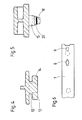
- La figure 2 est une vue de détail du téton fendu.
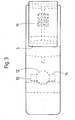
- La figure 3 est une vue de dessus de la pièce de forme.
- La figure 4 est une section selon III-III de la pièce de forme selon figure 1.
- La figure 5 est une vue en coupe selon IV-IV de la figure 1.
- La figure 6 est une vue en plan de l'extrémité de la bande à laquelle est fixée la pièce de forme, avant la fixation de celle-ci.
- La bague de cerclage et de stockage partiellement représentée à la figure 1 est constituée d'une bande 1 dont une extrémité est venue d'une pièce avec une boucle 2 articulée à l'extrémité de la bande 1 au moyen d'une biellette 3. La boucle 2, en forme de capot, présente un bord frontal 4 venant s'accrocher sur le bec 5 d'une pièce de forme fixée à l'autre extrémité de la bande 1 et présentant un crochet 6 destiné à la suspension de la bague sur un support de rangement. Dans la position représentée à la figure 1 la bague est fermée, les deux extrémités de la bande 1 se rejoignant en 7.
- L'extrémité de la bande 1 portant la pièce de forme présente un trou 8 constitué par l'intersection d'une fente rectangulaire longitudinale et d'un trou circulaire et un trou carré 9 (figure 6). La pièce de forme est fixée dans ces trous 8 et 9 par deux parties saillantes 10 et 11.
- La partie saillante 10 est constituée d'un pied central cylindrique 12 de diamètre très légèrement inférieur au diamètre de la partie cylindrique du trou 8, ce pied 12 présentant deux bras radiaux 13 et 14 (figure 4) de section essentiellement rectangulaire et dont la longueur totale est legèrement inférieure à la longueur de la fente 8. La saillie 10 et le trou 8 constituent ensemble une fixation à baionnette.
- Le téton fendu 11 est de section carrée. Comme représenté aux figures 2 et 5, il présente une première partie 15 de section légèrement inférieure à celle du trou carré 9 de la bande 1 et une seconde partie 16 de section maximale sensiblement supérieure à celle du trou carré 9, mais allant en se rétrécissant vers l'extrémité du téton dont la fente 17 s'étend jusqu'à la base du téton. L'extrémité de l'une des parties du téton fendu 11 est reliée à un plot cylindrique 18, de diamètre supérieur à la largeur de la fente 17, par un bras radial 19. Le tout est bien entendu venu d'une pièce de moulage. Les parois de la fente 17 présentent en outre deux dépressions 20 et 21 correspondant à une surface cylindrique de diamètre légèrement inférieur au diamètre du plot 18.
- Pour fixer la pièce de forme à la bande 1, on introduit la saillie 10 dans le trou 8 de la bande en plaçant la pièce de forme transversalement à la bande puis on fait tourner celle-ci de 90* et l'on enfonce le téton fendu 11 dans le trou 9. La pièce de forme est ainsi retenue d'une part par les bras 13 et 14 de sa saillie 10 et, d'autre part, par les deux portées rectangulaires 22 et 23 du téton fendu 11. On enfonce ensuite le plot cylindrique 18- dans la fente 17, ce plot 18 venant se loger dans les dépressions cylindriques 20 et 21. La fente d'élasticité du téton fendu est ainsi supprimée et la fixation de la pièce de forme par ce téton fendu est parfaitement assurée.
Claims (2)
Priority Applications (1)
| Application Number | Priority Date | Filing Date | Title |
|---|---|---|---|
| AT85200794T ATE31837T1 (de) | 1984-05-29 | 1985-05-20 | Verschluss- und speicherring fuer aufzeichnungsbandspule. |
Applications Claiming Priority (2)
| Application Number | Priority Date | Filing Date | Title |
|---|---|---|---|
| FR8408423 | 1984-05-29 | ||
| FR8408423A FR2565393B1 (fr) | 1984-05-29 | 1984-05-29 | Bague de cerclage et de stockage pour bobine de ruban d'enregistrement |
Publications (2)
| Publication Number | Publication Date |
|---|---|
| EP0164791A1 true EP0164791A1 (fr) | 1985-12-18 |
| EP0164791B1 EP0164791B1 (fr) | 1988-01-07 |
Family
ID=9304500
Family Applications (1)
| Application Number | Title | Priority Date | Filing Date |
|---|---|---|---|
| EP85200794A Expired EP0164791B1 (fr) | 1984-05-29 | 1985-05-20 | Bague de cerclage et de stockage pour bobine de ruban d'enregistrement |
Country Status (11)
| Country | Link |
|---|---|
| EP (1) | EP0164791B1 (fr) |
| JP (1) | JPS6157088A (fr) |
| AT (1) | ATE31837T1 (fr) |
| AU (1) | AU4288885A (fr) |
| BR (1) | BR8502447A (fr) |
| CA (1) | CA1250256A (fr) |
| DE (1) | DE3561366D1 (fr) |
| ES (1) | ES287097Y (fr) |
| FR (1) | FR2565393B1 (fr) |
| MX (1) | MX157188A (fr) |
| SU (1) | SU1449029A3 (fr) |
Cited By (2)
| Publication number | Priority date | Publication date | Assignee | Title |
|---|---|---|---|---|
| EP0259554A3 (fr) * | 1986-09-09 | 1989-07-26 | Gefitec S.A. | Bague de cerclage et de stockage pour bobine de ruban d'enregistrement |
| EP0994282A3 (fr) * | 1998-10-16 | 2002-01-02 | Officina Stagnoli di Stagnoli Laurina | Sections crémaillère droites ou courbées pour fixation à crochets sur une barre de support |
Citations (2)
| Publication number | Priority date | Publication date | Assignee | Title |
|---|---|---|---|---|
| US3696935A (en) * | 1969-12-24 | 1972-10-10 | Wright Barry Corp | Reel sealing and storage apparatus |
| US4388991A (en) * | 1981-07-09 | 1983-06-21 | Price Macy J | Sealing and storage ring with latch apparatus |
-
1984
- 1984-05-29 FR FR8408423A patent/FR2565393B1/fr not_active Expired
-
1985
- 1985-05-20 DE DE8585200794T patent/DE3561366D1/de not_active Expired
- 1985-05-20 AT AT85200794T patent/ATE31837T1/de not_active IP Right Cessation
- 1985-05-20 EP EP85200794A patent/EP0164791B1/fr not_active Expired
- 1985-05-23 JP JP60109463A patent/JPS6157088A/ja active Pending
- 1985-05-24 BR BR8502447A patent/BR8502447A/pt unknown
- 1985-05-27 AU AU42888/85A patent/AU4288885A/en not_active Abandoned
- 1985-05-27 ES ES1985287097U patent/ES287097Y/es not_active Expired
- 1985-05-28 MX MX205414A patent/MX157188A/es unknown
- 1985-05-28 CA CA000482530A patent/CA1250256A/fr not_active Expired
- 1985-05-28 SU SU853899850A patent/SU1449029A3/ru active
Patent Citations (2)
| Publication number | Priority date | Publication date | Assignee | Title |
|---|---|---|---|---|
| US3696935A (en) * | 1969-12-24 | 1972-10-10 | Wright Barry Corp | Reel sealing and storage apparatus |
| US4388991A (en) * | 1981-07-09 | 1983-06-21 | Price Macy J | Sealing and storage ring with latch apparatus |
Cited By (2)
| Publication number | Priority date | Publication date | Assignee | Title |
|---|---|---|---|---|
| EP0259554A3 (fr) * | 1986-09-09 | 1989-07-26 | Gefitec S.A. | Bague de cerclage et de stockage pour bobine de ruban d'enregistrement |
| EP0994282A3 (fr) * | 1998-10-16 | 2002-01-02 | Officina Stagnoli di Stagnoli Laurina | Sections crémaillère droites ou courbées pour fixation à crochets sur une barre de support |
Also Published As
| Publication number | Publication date |
|---|---|
| AU4288885A (en) | 1985-12-05 |
| FR2565393B1 (fr) | 1986-09-26 |
| EP0164791B1 (fr) | 1988-01-07 |
| MX157188A (es) | 1988-10-31 |
| FR2565393A1 (fr) | 1985-12-06 |
| DE3561366D1 (en) | 1988-02-11 |
| BR8502447A (pt) | 1986-01-28 |
| ES287097Y (es) | 1986-07-16 |
| JPS6157088A (ja) | 1986-03-22 |
| ES287097U (es) | 1985-12-16 |
| SU1449029A3 (ru) | 1988-12-30 |
| ATE31837T1 (de) | 1988-01-15 |
| CA1250256A (fr) | 1989-02-21 |
Similar Documents
| Publication | Publication Date | Title |
|---|---|---|
| FR1450241A (fr) | Perfectionnements aux boîtes d'emballages | |
| CH388181A (fr) | Dispositif de fermeture inviolable d'un récipient | |
| FR2586652A1 (fr) | Emballage pour une paire de ciseaux | |
| FR2610906A1 (fr) | Boite de rangement de bobines de films pour photographe | |
| FR2857709A1 (fr) | Mousqueton a deux doigts opposes | |
| EP0346177B1 (fr) | Dispositif de fixation d'un tableau ou similaire à l'intérieur d'un cadre | |
| EP0574284B1 (fr) | Boîtier muni d'un dispositif de fermeture ne comportant pas d'organe mobile | |
| EP0286561B1 (fr) | Collier à vis de serrage pivotante | |
| EP0164791B1 (fr) | Bague de cerclage et de stockage pour bobine de ruban d'enregistrement | |
| CH420968A (fr) | Caissette repliable | |
| EP2766288B1 (fr) | Dispositif manuel d'application par ruban d'un revetement sur un support a embout ameliore | |
| FR2504858A1 (fr) | Cassette de ruban encreur pour machines a ecrire, imprimantes ou machines analogues | |
| FR2814138A1 (fr) | Pret-a-monter de fixation d'un porte-bidon | |
| FR2690486A1 (fr) | Pince à serrage instantané et à ouverture et à force de serrage réglables, et porte-copie équipé d'une telle pince. | |
| EP0164790A1 (fr) | Bague de cerclage et de stockage pour bobine de ruban d'enregistrement | |
| FR2540078A1 (fr) | Fut non metallique rigide perfectionne | |
| FR2693885A1 (fr) | Porte-pinceaux. | |
| FR2797798A1 (fr) | Boite destinee a contenir des objets allonges | |
| FR2737388A1 (fr) | Porte moulinet pour canne a peche | |
| EP0675050A1 (fr) | Dispositif de bouchage pour récipient à parois souples | |
| FR2677340A1 (fr) | Epsilonnrouleur de sangle d'arrimage. | |
| BE1006944A6 (fr) | Outil pour vider des tubes contenant une substance liquide ou pateuse. | |
| EP4527755A1 (fr) | Loquet pour palette, kit de montage d'un loquet, procédé d'installation d'un loquet et palette associée | |
| BE557389A (fr) | ||
| FR2492519A1 (fr) | Dispositif de mesure a ruban comprenant des moyens d'accrochage |
Legal Events
| Date | Code | Title | Description |
|---|---|---|---|
| PUAI | Public reference made under article 153(3) epc to a published international application that has entered the european phase |
Free format text: ORIGINAL CODE: 0009012 |
|
| AK | Designated contracting states |
Designated state(s): AT BE CH DE GB IT LI NL SE |
|
| 17P | Request for examination filed |
Effective date: 19851114 |
|
| 17Q | First examination report despatched |
Effective date: 19870511 |
|
| GRAA | (expected) grant |
Free format text: ORIGINAL CODE: 0009210 |
|
| AK | Designated contracting states |
Kind code of ref document: B1 Designated state(s): AT BE CH DE GB IT LI NL SE |
|
| REF | Corresponds to: |
Ref document number: 31837 Country of ref document: AT Date of ref document: 19880115 Kind code of ref document: T |
|
| REF | Corresponds to: |
Ref document number: 3561366 Country of ref document: DE Date of ref document: 19880211 |
|
| ITF | It: translation for a ep patent filed | ||
| GBT | Gb: translation of ep patent filed (gb section 77(6)(a)/1977) | ||
| PLBE | No opposition filed within time limit |
Free format text: ORIGINAL CODE: 0009261 |
|
| STAA | Information on the status of an ep patent application or granted ep patent |
Free format text: STATUS: NO OPPOSITION FILED WITHIN TIME LIMIT |
|
| 26N | No opposition filed | ||
| PGFP | Annual fee paid to national office [announced via postgrant information from national office to epo] |
Ref country code: DE Payment date: 19900319 Year of fee payment: 6 |
|
| PGFP | Annual fee paid to national office [announced via postgrant information from national office to epo] |
Ref country code: CH Payment date: 19900330 Year of fee payment: 6 |
|
| PGFP | Annual fee paid to national office [announced via postgrant information from national office to epo] |
Ref country code: GB Payment date: 19900420 Year of fee payment: 6 |
|
| PGFP | Annual fee paid to national office [announced via postgrant information from national office to epo] |
Ref country code: SE Payment date: 19900511 Year of fee payment: 6 |
|
| PGFP | Annual fee paid to national office [announced via postgrant information from national office to epo] |
Ref country code: AT Payment date: 19900515 Year of fee payment: 6 |
|
| ITTA | It: last paid annual fee | ||
| PGFP | Annual fee paid to national office [announced via postgrant information from national office to epo] |
Ref country code: NL Payment date: 19900531 Year of fee payment: 6 |
|
| PGFP | Annual fee paid to national office [announced via postgrant information from national office to epo] |
Ref country code: BE Payment date: 19900601 Year of fee payment: 6 |
|
| PG25 | Lapsed in a contracting state [announced via postgrant information from national office to epo] |
Ref country code: GB Effective date: 19910520 Ref country code: AT Effective date: 19910520 |
|
| PG25 | Lapsed in a contracting state [announced via postgrant information from national office to epo] |
Ref country code: SE Effective date: 19910521 |
|
| PG25 | Lapsed in a contracting state [announced via postgrant information from national office to epo] |
Ref country code: LI Effective date: 19910531 Ref country code: CH Effective date: 19910531 Ref country code: BE Effective date: 19910531 |
|
| BERE | Be: lapsed |
Owner name: S.A. GEFITEC Effective date: 19910531 |
|
| PG25 | Lapsed in a contracting state [announced via postgrant information from national office to epo] |
Ref country code: NL Effective date: 19911201 |
|
| GBPC | Gb: european patent ceased through non-payment of renewal fee | ||
| NLV4 | Nl: lapsed or anulled due to non-payment of the annual fee | ||
| REG | Reference to a national code |
Ref country code: CH Ref legal event code: PL |
|
| PG25 | Lapsed in a contracting state [announced via postgrant information from national office to epo] |
Ref country code: DE Effective date: 19920303 |
|
| EUG | Se: european patent has lapsed |
Ref document number: 85200794.7 Effective date: 19911209 |