EP0164824A2 - Mécanisme de serrage du couteau d'un microtome - Google Patents
Mécanisme de serrage du couteau d'un microtome Download PDFInfo
- Publication number
- EP0164824A2 EP0164824A2 EP85301935A EP85301935A EP0164824A2 EP 0164824 A2 EP0164824 A2 EP 0164824A2 EP 85301935 A EP85301935 A EP 85301935A EP 85301935 A EP85301935 A EP 85301935A EP 0164824 A2 EP0164824 A2 EP 0164824A2
- Authority
- EP
- European Patent Office
- Prior art keywords
- cutter
- clamping
- clamping mechanism
- body portion
- mechanism according
- Prior art date
- Legal status (The legal status is an assumption and is not a legal conclusion. Google has not performed a legal analysis and makes no representation as to the accuracy of the status listed.)
- Granted
Links
- 230000007246 mechanism Effects 0.000 title claims abstract description 54
- 239000011521 glass Substances 0.000 claims description 23
- 230000000295 complement effect Effects 0.000 claims description 7
- 239000000463 material Substances 0.000 description 4
- 239000002184 metal Substances 0.000 description 4
- 229920003023 plastic Polymers 0.000 description 4
- 239000004033 plastic Substances 0.000 description 4
- 229910000831 Steel Inorganic materials 0.000 description 3
- 238000010276 construction Methods 0.000 description 3
- 239000010959 steel Substances 0.000 description 3
- 238000009966 trimming Methods 0.000 description 3
- 239000000919 ceramic Substances 0.000 description 2
- 239000012634 fragment Substances 0.000 description 2
- 241000078511 Microtome Species 0.000 description 1
- 210000000988 bone and bone Anatomy 0.000 description 1
- 210000001519 tissue Anatomy 0.000 description 1
Images


Classifications
-
- G—PHYSICS
- G01—MEASURING; TESTING
- G01N—INVESTIGATING OR ANALYSING MATERIALS BY DETERMINING THEIR CHEMICAL OR PHYSICAL PROPERTIES
- G01N1/00—Sampling; Preparing specimens for investigation
- G01N1/02—Devices for withdrawing samples
- G01N1/04—Devices for withdrawing samples in the solid state, e.g. by cutting
- G01N1/06—Devices for withdrawing samples in the solid state, e.g. by cutting providing a thin slice, e.g. microtome
-
- G—PHYSICS
- G01—MEASURING; TESTING
- G01N—INVESTIGATING OR ANALYSING MATERIALS BY DETERMINING THEIR CHEMICAL OR PHYSICAL PROPERTIES
- G01N1/00—Sampling; Preparing specimens for investigation
- G01N1/02—Devices for withdrawing samples
- G01N1/04—Devices for withdrawing samples in the solid state, e.g. by cutting
- G01N1/06—Devices for withdrawing samples in the solid state, e.g. by cutting providing a thin slice, e.g. microtome
- G01N2001/061—Blade details
Definitions
- This invention relates to a clamping mechanism for the cutter of a microtome, wherein the cutter is clampable in a cutter mounting located on a base.
- Cutters having the widest variety of cutting edge geometries, and made of different materials, are known for the various specimens required to be cut into thin sections. Such specimens include tissue fragments, bone fragments, plastic parts, metal parts and the like embedded in plastic material. Suitable cutters are made of glass, ceramics, hard metal or steel, for example. Due to their different cutting edge geometries, it is necessary to clamp the different cutters in clamping mechanisms specifically adapted to them. Exchanging one clamping mechanism for another clamping mechanism is relatively complicated, so that known microtomes require relatively long down times in order to perform the exchange operation. It becomes still more complicated when the microtome clamping mechanism is constructed in such a way that the cutting angle of the cutter is adjustable relative to the microtome base plate.
- a cutting angle adjustment facility gives the advantage that a cutter clamped into the clamping mechanism can be optimally adjusted relative to the specimen to be thinly sectioned in order to perform an excellent thin sectioning operation.
- different bases adapted in shape to the different cutter mountings are required for each of the known cutters, which include for example triangular glass cutters, Ralph glass cutters, standard microtome cutters, blade-shaped one-way cutters, hard metal blades and steel blades. In this context it is not only complicted to change the bases and the corresponding cutter mountings, but it is also necessary to keep a large stock of the widest variety of bases.
- a clamping mechanism for a microtome cutter wherein the cutter is clampable in a cutter mounting located on a base, the cutter mounting being mounted pivotably upon a uniformly curved sliding surface formed in the base, and the axis of rotation of the mounting on the base being coincident with the cutting edge of the cutter.
- the clamping mechanism according to the invention has the particular advantage that only a single base, about which the various cutter mountings are pivotable in order to adjust to any desired cutting angle, is necessary for the widest variety of cutter mountings.
- this precise cutting angle adjustment which is also simple to perform, it is possible for the first time to utilise the various cutters optimally in conjunction with one base on the microtome.
- Such a precise adjustment of a desired cutting angle gives the further advantage that the thin sections obtained exhibit an excellent quality of cut.
- the base may be provided with at least one locking means, preferably passing through the sliding mechanism, by which the cutter mounting is clampable on the sliding surface of the base.
- This locking means can be extremely simple both in construction and in operation, so that the various cutter mountings can be changed rapidly when required, without prejudicing the precise positioning of the cutter mounting and hence of a cutter clamped in the mounting.
- the clamping mechanism according to the invention advantageously creates an integral clamping system between the base, which may be fastened rigidly to the microtome, and the various cutter mountings, so that manipulation is substantially simplified and improved compared to known systems with bases adapted to the various cutter mountings.
- the locking means may comprise a radially adjustable, resiliently mounted tension piece having a transverse bore, an eccentric bar mounted in the cutter mounting and extending through the bore and through at least one side of the cutter mounting, and actuating means for the eccentric bar. Due to the radial adjustability of the tension piece, it is possible to simply adjust and readjust the tension piece for the various cutter mountings, even at the user's own premises. It is thus also possible extremely simply to compensate for dimensional tolerances in the various cutter mountings.
- the eccentric bar permits the locking device to be of extremely simple construction and to be quick and easy to operate.
- the cutter mounting may comprise a body portion having a rear surface complementary to the sliding surface in the base, and a recess for the tension piece in the rear surface thereof, the body portion being provided with means remote from the rear surface for clamping the cutter. Due to the rear surface of each of the various cutter mountings being complementary to the sliding surface in the base, it is simple to combine the various cutter mountings with one and the same base. A further advantage lies in the fact that these various cutter mountings are all pivotable upon the sliding surface in the base in the same way for adjusting the cutter to a desired cutting angle. Due to the recess for the tension piece of the locking means in the rear surface of each of the various cutter mountings, the clamping system is uniform for all the various cutter mountings.
- cutter mountings used for the various cutters can all be combined equally well and equally rapidly with a single base on the microtome, whilst all the cutter mountings are adjustable through the desired cutting angles in the same manner. The correct adjustment of the clearance angle allows individual thin sections of excellent quality to be achieved.
- the cutter mounting may include means for adjusting the cutter.
- the cutter may be adjusted both in a direction parallel to the cutting edge and also in a direction perpendicular thereto.
- These adjusting means permit the cutting edge to be aligned relative to the sliding surface in the base with such accuracy that the cutting edge comes to lie precisely along the axis of rotation of the cutter. In this position the cutter can be positioned at any desired cutting angle without problems, so that thin section specimens consisting of the widest variety of materials can be sectioned extremely accurately and precisely. Excellent thin sections are obtained by this means.
- the means for adjusting the cutter may comprise screws which are axially adjustable relative to the body portion of the cutter mounting, whilst the cutter may have opposite its cutting edge a narrow rear surface which lies against the leading ends of the screws.
- Two screws are preferably arranged with a lateral spacing between them, so that it is a simple matter to align and/or adjust the inclination of the cutter and particularly the inclination of the cutting edge to the horizontal, and/or to the thin section specimen.
- the body portion of the cutter mounting has a flat surface on that side opposite the rear surface and is provided with a straight guide means carrying an adjustable slide, which carries on its side opposite the straight guide means, an arcuate guide means in which a cutter trough is rotatably mounted.
- a clamping mechanism can be both slid in a straight line and also angled. This is particularly important for the initial trimming of thin section specimens embedded in plastics. It is possible in a very simple manner, with such a clamping mechanism, to slide a cutter straight to one side and to rotate it through up to 45°, for example. It is also possible with this embodiment of the clamping mechanism to adjust a desired cutting angle of the cutter with extreme precision.
- a cutter which is tensioned in such a clamping mechanism usually a triangular glass cutter, is adjustable in all three directions of space.
- the straight and the arcuate guide means may be dovetail guides.
- the adjusting means may be a worm drive mounted in the body portion, and the cutter trough for clamping a triangular glass cutter may be provided with two mutually opposed clamping jaws and a clamping screw arranged perpendicularly to, and engaged with, the clamping jaws.
- the cutter can be adjusted laterally with extreme precision by such a worm drive.
- the cutter trough can also be adjusted to any desired angle with equal precision. This is particularly necessary for the initial trimming of a thin section specimen.
- the cutter mounting comprises a body portion containing a guide cavity for a clamping jaw for a lamellar glass cutter, the jaw being actuable by eccentric means to clamp the glass cutter against the body portion.
- Glass cutters of this type are known as Ralph glass cutters, and are broken off from a glass strip 6 mm thick and -25 mm or 38 mm wide, for example.
- the clamping jaw can be drawn towards the body portion extremely simply and extremely rapidly by the eccentric device. Extremely efficacious and advantageous rapid tensioning of this type of cutter is achieved in this way.
- the body portion may include a backing flange, which the cutter abuts areally over its rear surface, and clamping means opposite the flange for clamping the cutter against the flange.
- Such a backing flange is provided particularly in clamping mechanisms for standard cutters, which are ground in grinding patterns c and d, for example.
- the areal contact of the standard cutter produces highly stable clamping in the clamping mechanism of the invention, and any desired cutting angle can be stably adjusted.
- the clamping means may comprise screws located in lateral uprights on the body portion.
- the clamping device comprises a wedge element guided in lateral uprights, which is adjustably movable towards and away from the cutting edge by eccentric means. Because of this eccentric means it is possible in very simple manner to clamp the wedge element between the lateral uprights and the cutter and to clamp the cutter firmly and reliably.
- the body portion may also be constructed as a wedge which includes a cutter mounting part with a recess on the one wedge surface and a clamping device on the second wedge surface, which is adjustable in at least in one direction relative to the body portion.
- a gap which is particuarly appropriate for mounting a bladeshaped cutter, can be formed between the recess of the cutter, mounting part fastened to the body portion and the adjustable clamping device in the region of the front edge of the body portion.
- Blade-shaped cutters of this type include those known as one-way blades, which may consist of hard metal, of steel or of ceramics.
- This clamping mechanism similarly to the various clamping mechanisms described above, may also advantageously be combined with a base and be pivoted relative to the base in order to adjust a desired cutting angle.
- the clamping device may be adjustable in one direction by eccentric means, and in a direction perpendicular thereto by means of at least one screw.
- the adjustment of the clamping device by the eccentric means takes place in the direction of the second wedge surface. It serves for tightening down or clamping fast a blade-shaped cutter between the cutter mounting part and the clamping device.
- the screw serves for adjusting the clamping device perpendicularly to the second wedge surface, that is to say it serves to adjust, or adapt to the thickness of a blade-shaped cutter, the gap formed between the recess in the cutter mounting part and the clamping device.
- Figures 1 and 2 show a clamping mechanism 10 for a microtome cutter 12.
- the cutter is clampable in a cutter mounting 16 located on a base 14.
- the cutter mounting is mounted pivotably upon a uniformly curved sliding surface 18 formed in the base. The axis of rotation of the surface 18 is coincident with the cutting edge 20 of the cutter. In this manner the cutter mounting can be turned on the sliding surface in order to adjust to a desired cutting angle.
- the base 14 is provided with at least one locking device 22 extending beyond the sliding surface 18 for clamping the cutter mounting 16 on the sliding surface.
- the locking device 22 comprises a tension piece 28 which is radially adjustable by means of a screw 24, is resiliently mounted by virtue of a coil spring 26, and has a transverse bore 30.
- An eccentric bar 32 is mounted in the cutter mounting 16 and extends through the bore and through at least one side of the cutting mounting 16, and is provided with an actuating member 34.
- the cutter mounting 16 comprises a body portion 36 with a rear surface complementary to the sliding surface 18 in the base 14 and in which a recess -38 for the tension piece 28 is provided.
- the body portion 36 is provided with means remote from the rear surface for clamping the cutter 12.
- the body portion 36 of the cutter mounting 16 has a flat surface on its side opposite the rear surface, and is provided with a straight guide means 40.
- the slide 42 carries, on its side opposite the guide means 40, an arcuate guide means 46 in which a cutter trough 48 is rotatably mounted.
- the straight and the arcuate guide means 40 and 46 are constructed as dovetail guides.
- the adjusting means 44 in this embodiment is a worm drive mounted in the body portion 36.
- the cutter trough 48 is provided with two opposed clamping jaws 50 and a clamping screw 52 arranged perpendicularly to and engaged with these clamping jaws for clamping a triangular glass cutter 12.
- triangular glass cutters 12 with a thickness in the range between 6 mm and 12 mm can be clamped between the clamping jaws 50 by means of the clamping screws 52.
- the triangular glass cutter 12 is slidable laterally along the straight guide means 40, and can be angled, for example through 45° in each direction, around the second guide means 46, for the initial trimming of a thin section specimen embedded in plastics and designated by the reference numeral 56 in Figure 1.
- the straight lateral sliding is indicated by the double arrow A in Figure 1, and the angular movement to each side by the double arrow B.
- the slide 42 can be moved in the direction of the arrow A along the guide means 40 by the adjusting means 44, which comprises a screwthreaded spindle, by turning the rotary knobs 58 in the direction of the arrows C. Adjustment of the cutting angle, which is indicated by the arrow D in Figure 2, is made possible by the arcuate sliding surface 18 of the base - 14.
- FIGs 3 and 4 show a clamping mechanism 10 for a Ralph glass cutter 12 which is clampable in a cutter mounting 16 located on a base 14.
- the cutter mounting is again, as in the clamping mechanism shown in Figures 1 and 2, mounted pivotably upon a uniformly curved sliding surface 18 formed in the base, the axis of rotation of the surface being coincident with the cutting edge 20 of the cutter.
- the base 14 is provided with a locking device 22 extending beyond the sliding surface 18 for clamping the cutter mounting 16 on the sliding surface after adjusting the Ralph glass cutter 12 to a desired cutting angle.
- the locking device 22 comprises a tension piece 28 having a transverse bore 30, a screw 24 engaged with the tension piece, and a coil spring 26. In this manner the tension piece is radially adjustable and is resiliently mounted.
- An eccentric bar 32 is mounted in the cutter mounting and extends through the bore 30 and through one side of the cutter mounting, and is provided with an actuating member 34.
- the eccentric bar is rotated in the transverse bore of the tension piece so that either the body portion 36 of the cutter mounting is clamped by its rear surface against the sliding surface 18 of the base 14, or the locking between the body portion and the base is released, assisted by the coil spring 26.
- the cutter mounting 16 comprises a body portion 36 with a rear surface complementary to the sliding surface 18 in the base 14 and in which a recess 38 for the tension piece 28 is provided.
- the body portion 36 is provided with means remote from the rear surface for clamping the cutter 12.
- the cutter mounting also comprises means for adjusting the Ralph cutter 12. These means for adjusting the cutter comprise screws 60, which are axially adjustable relative to the body portion 36, whilst the cutter rests by its narrow rear surface 64, opposite its cutting edge 20, upon the leading ends 62 of the screws. It is simple to adjust the inclination of the cutting edge relative to the horizontal by means of these screws.
- the body portion 36 of the cutter mounting 16 contains a guide cavity 66 for a clamping jaw 68 for mounting a Ralph glass cutter 12, whilst the jaw is actuable by eccentric means 70 to clamp the glass cutter against the body portion.
- the movement of the clamping jaw to clamp the glass cutter in the clamping mechanism 10 is indicated by the double arrow E in Figure 3.
- the clamping jaw is slidable on the eccentric means 70 in the direction of the double arrow F shown in Figure 3, so that the cutting edge 20 of the cutter can be utilised across its entire width.
- the eccentric means 70 is provided with a rotary actuating knob 72.
- Figures 5 and 6 show a clamping mechanism 10 for a standard cutter 12, which is clampable in a cutter mounting 16 located on a base 14.
- the cutter mounting is mounted pivotably upon a uniformly curved sliding surface 18 formed in the base. The axis of rotation of the surface 18 is coincident with the cutting edge 20 of the standard cutter.
- the base 14 is provided with a locking device 22 which extends beyond the sliding surface 18 of the base 14.
- the cutter mounting 16 is clampable on the sliding surface by this locking device.
- the locking device comprises a tension piece 28 with a transverse bore 30, through which extends an eccentric bar 32 provided with an actuating member 34.
- the eccentric bar can be rotated in the transverse bore by means of this actuating member so that the body portion 36 of the cutter mounting is either clamped or pivotable on the sliding surface of the base.
- the body portion of the cutter mounting comprises a rear surface, complementary to the sliding surface 18, provided with a recess 38 for the tension piece 28.
- the body portion 36 is also provided with means remote from the rear surface for clamping the cutter 12.
- the cutter mounting 16 comprises means for adjusting the cutter.
- the means for adjusting the cutter 12 are constructed as screws 60, which are axially adjustable relative to the body portion 36 in the direction of the double arrow G, whilst the cutter 12 rests by its narrow rear surface 64, opposite its cutting edge 20, upon the leading ends 62 of the screws 60.
- the body portion 36 includes a backing flange 74, which the cutter 12 abuts areally over its rear surface.
- a clamping means 76 is provided on the body portion opposite the backing flange for clamping the standard cutter against the backing flange.
- the clamping means 76 is formed by screws which are located in lateral uprights 78 on the body portion of the mounting.
- the clamping means may also comprise a wedge element, adjustable by eccentric means towards and away from the cutting edge and guided in lateral uprights.
- a wedge element cooperating with eccentric means produces a rapid clamping means of simple construction.
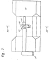
- FIGs 7 and 8 show a base 14 with a locking device 22 extending beyond the sliding surface 18, by which each of the cutter mountings 16 previously- described and illustrated in the Figures 1 to 6 are clampable on the sliding surface of the base 14.
- the locking device 22 comprises a tension piece 28, which is radially adjustable by means of a screw 24 and resiliently- mounted by means of the coil spring 26, with a transverse bore 30 through which an eccentric bar 32 extends.
- the bar is sufficiently long, at least on one side, that it extends over the base 14 and is connected at its end to an actuating member 34.
Landscapes
- Physics & Mathematics (AREA)
- Health & Medical Sciences (AREA)
- Life Sciences & Earth Sciences (AREA)
- Chemical & Material Sciences (AREA)
- Analytical Chemistry (AREA)
- Biochemistry (AREA)
- General Health & Medical Sciences (AREA)
- General Physics & Mathematics (AREA)
- Immunology (AREA)
- Pathology (AREA)
- Sampling And Sample Adjustment (AREA)
Priority Applications (1)
| Application Number | Priority Date | Filing Date | Title |
|---|---|---|---|
| AT85301935T ATE80946T1 (de) | 1984-04-07 | 1985-03-20 | Klemmvorrichtung fuer das messer eines mikrotomes. |
Applications Claiming Priority (2)
| Application Number | Priority Date | Filing Date | Title |
|---|---|---|---|
| DE19843413278 DE3413278C2 (de) | 1983-07-30 | 1984-04-07 | Klemmvorrichtung für das Schneidmesser eines Mikrotomes |
| DE3413278 | 1984-04-07 |
Publications (3)
| Publication Number | Publication Date |
|---|---|
| EP0164824A2 true EP0164824A2 (fr) | 1985-12-18 |
| EP0164824A3 EP0164824A3 (en) | 1987-01-07 |
| EP0164824B1 EP0164824B1 (fr) | 1992-09-23 |
Family
ID=6233040
Family Applications (1)
| Application Number | Title | Priority Date | Filing Date |
|---|---|---|---|
| EP85301935A Expired - Lifetime EP0164824B1 (fr) | 1984-04-07 | 1985-03-20 | Mécanisme de serrage du couteau d'un microtome |
Country Status (3)
| Country | Link |
|---|---|
| EP (1) | EP0164824B1 (fr) |
| JP (1) | JPH0678972B2 (fr) |
| AT (1) | ATE80946T1 (fr) |
Families Citing this family (1)
| Publication number | Priority date | Publication date | Assignee | Title |
|---|---|---|---|---|
| DE102015204013B3 (de) * | 2015-03-05 | 2016-04-14 | Pfm Medical Ag | Vorrichtung zum positionsgenauen Halten eines Messers oder einer Klinge auf dem Schlitten eines Schlittenmikrotoms und Schlittenmikrotom |
Family Cites Families (9)
| Publication number | Priority date | Publication date | Assignee | Title |
|---|---|---|---|---|
| DE1247685B (de) * | 1963-11-11 | 1967-08-17 | Compur Werk Gmbh & Co | Einstellvorrichtung fuer Mikrotom-Messer |
| AT267217B (de) * | 1967-07-27 | 1968-12-27 | Reichert Optische Werke Ag | Einrichtung zum Justieren des Flüssigkeitsspiegels in Schnittsammelbecken von Ultramikrotomen |
| GB1307974A (en) * | 1968-10-16 | 1973-02-21 | Nat Res Dev | Microtomes |
| JPS485912U (fr) * | 1971-05-31 | 1973-01-23 | ||
| DE2143529C3 (de) * | 1971-08-31 | 1979-07-05 | R. Jung, Zweigniederlassung Der Fritz Schwarzer Gmbh, 6901 Nussloch | Mikrotom |
| JPS51134489A (en) * | 1975-05-19 | 1976-11-20 | Hitachi Ltd | Microtome |
| DE3224375C2 (de) * | 1982-06-30 | 1984-09-20 | C. Reichert Optische Werke Ag, Wien | Vorrichtung zur Überprüfung der Qualität des Messers an einem Mikrotom, insbesondere Ultramikrotom |
| EP0158484A3 (fr) * | 1984-04-07 | 1987-01-07 | Cambridge Instruments GmbH | Mécanisme de serrage du couteau d'un microtome |
| EP0159155A3 (fr) * | 1984-04-07 | 1987-01-21 | Cambridge Instruments GmbH | Mécanisme de serrage du couteau d'un microtome |
-
1985
- 1985-03-20 EP EP85301935A patent/EP0164824B1/fr not_active Expired - Lifetime
- 1985-03-20 AT AT85301935T patent/ATE80946T1/de not_active IP Right Cessation
- 1985-04-08 JP JP60074146A patent/JPH0678972B2/ja not_active Expired - Lifetime
Also Published As
| Publication number | Publication date |
|---|---|
| JPS60235034A (ja) | 1985-11-21 |
| EP0164824B1 (fr) | 1992-09-23 |
| EP0164824A3 (en) | 1987-01-07 |
| ATE80946T1 (de) | 1992-10-15 |
| JPH0678972B2 (ja) | 1994-10-05 |
Similar Documents
| Publication | Publication Date | Title |
|---|---|---|
| US5431068A (en) | Blade sharpener | |
| US5582542A (en) | Apparatus and method for sharpening a cutting tool | |
| US4142332A (en) | Drill grinding fixture | |
| EP0278154B1 (fr) | Machine pour couper obliquement des nattes | |
| US5148730A (en) | Sawmark guide | |
| US4700600A (en) | Microtome disposable blade apparatus | |
| US5379669A (en) | Precision miter gauge | |
| US7549910B2 (en) | Blade sharpening holder | |
| US20040154448A1 (en) | Fine-adjustment mechanism to preset a miter saw for precision miter cuts | |
| US3733948A (en) | Self aligning base clamp and holder for disposable blade and water bath for microtomes and method | |
| GB2298498A (en) | Blade holding device for microtomes | |
| US5964138A (en) | Clamping device for a blade-shaped cutting knife of a microtome | |
| JPH0526792A (ja) | ミクロトーム | |
| US3599523A (en) | Disposable blade and holder for microtome | |
| US20120304829A1 (en) | Chain Saw Sharpener | |
| US5099735A (en) | Versatile knife holder for microtome knives | |
| EP0159155A2 (fr) | Mécanisme de serrage du couteau d'un microtome | |
| EP0164824A2 (fr) | Mécanisme de serrage du couteau d'un microtome | |
| US6058824A (en) | Cutter holder for accommodating wedge-shaped microtome cutters | |
| GB2182881A (en) | A blade holder for a microtome | |
| GB2145241A (en) | Clamping mechanism for the cutter of a microtome | |
| CA2500495A1 (fr) | Jauge d'assemblage a onglet et cloture de guidage du betail | |
| GB2148528A (en) | Clamping mechanism for a cutter of a microtome | |
| US3952459A (en) | Drill grinder | |
| US4628642A (en) | Device for sharpening circular knives |
Legal Events
| Date | Code | Title | Description |
|---|---|---|---|
| PUAI | Public reference made under article 153(3) epc to a published international application that has entered the european phase |
Free format text: ORIGINAL CODE: 0009012 |
|
| AK | Designated contracting states |
Designated state(s): AT FR SE |
|
| PUAL | Search report despatched |
Free format text: ORIGINAL CODE: 0009013 |
|
| AK | Designated contracting states |
Kind code of ref document: A3 Designated state(s): AT FR SE |
|
| 17P | Request for examination filed |
Effective date: 19870622 |
|
| 17Q | First examination report despatched |
Effective date: 19881214 |
|
| RAP1 | Party data changed (applicant data changed or rights of an application transferred) |
Owner name: CAMBRIDGE INSTRUMENTS GMBH |
|
| RAP1 | Party data changed (applicant data changed or rights of an application transferred) |
Owner name: LEICA INSTRUMENTS GMBH |
|
| GRAA | (expected) grant |
Free format text: ORIGINAL CODE: 0009210 |
|
| AK | Designated contracting states |
Kind code of ref document: B1 Designated state(s): AT FR SE |
|
| REF | Corresponds to: |
Ref document number: 80946 Country of ref document: AT Date of ref document: 19921015 Kind code of ref document: T |
|
| ET | Fr: translation filed | ||
| PLBE | No opposition filed within time limit |
Free format text: ORIGINAL CODE: 0009261 |
|
| STAA | Information on the status of an ep patent application or granted ep patent |
Free format text: STATUS: NO OPPOSITION FILED WITHIN TIME LIMIT |
|
| 26N | No opposition filed | ||
| PGFP | Annual fee paid to national office [announced via postgrant information from national office to epo] |
Ref country code: FR Payment date: 19940325 Year of fee payment: 10 |
|
| PGFP | Annual fee paid to national office [announced via postgrant information from national office to epo] |
Ref country code: SE Payment date: 19940329 Year of fee payment: 10 |
|
| PGFP | Annual fee paid to national office [announced via postgrant information from national office to epo] |
Ref country code: AT Payment date: 19940331 Year of fee payment: 10 |
|
| EAL | Se: european patent in force in sweden |
Ref document number: 85301935.4 |
|
| PG25 | Lapsed in a contracting state [announced via postgrant information from national office to epo] |
Ref country code: AT Effective date: 19950320 |
|
| PG25 | Lapsed in a contracting state [announced via postgrant information from national office to epo] |
Ref country code: SE Effective date: 19950321 |
|
| PG25 | Lapsed in a contracting state [announced via postgrant information from national office to epo] |
Ref country code: FR Free format text: LAPSE BECAUSE OF NON-PAYMENT OF DUE FEES Effective date: 19951130 |
|
| EUG | Se: european patent has lapsed |
Ref document number: 85301935.4 |
|
| REG | Reference to a national code |
Ref country code: FR Ref legal event code: ST |