EP0164897A2 - Dispositif pour le dosage d'un liquide - Google Patents
Dispositif pour le dosage d'un liquide Download PDFInfo
- Publication number
- EP0164897A2 EP0164897A2 EP85303296A EP85303296A EP0164897A2 EP 0164897 A2 EP0164897 A2 EP 0164897A2 EP 85303296 A EP85303296 A EP 85303296A EP 85303296 A EP85303296 A EP 85303296A EP 0164897 A2 EP0164897 A2 EP 0164897A2
- Authority
- EP
- European Patent Office
- Prior art keywords
- bladder
- vessel
- pipeline
- conduit
- valve
- Prior art date
- Legal status (The legal status is an assumption and is not a legal conclusion. Google has not performed a legal analysis and makes no representation as to the accuracy of the status listed.)
- Withdrawn
Links
Images



Classifications
-
- C—CHEMISTRY; METALLURGY
- C02—TREATMENT OF WATER, WASTE WATER, SEWAGE, OR SLUDGE
- C02F—TREATMENT OF WATER, WASTE WATER, SEWAGE, OR SLUDGE
- C02F1/00—Treatment of water, waste water, or sewage
- C02F1/68—Treatment of water, waste water, or sewage by addition of specified substances, e.g. trace elements, for ameliorating potable water
- C02F1/685—Devices for dosing the additives
- C02F1/686—Devices for dosing liquid additives
-
- B—PERFORMING OPERATIONS; TRANSPORTING
- B01—PHYSICAL OR CHEMICAL PROCESSES OR APPARATUS IN GENERAL
- B01J—CHEMICAL OR PHYSICAL PROCESSES, e.g. CATALYSIS OR COLLOID CHEMISTRY; THEIR RELEVANT APPARATUS
- B01J4/00—Feed or outlet devices; Feed or outlet control devices
- B01J4/008—Feed or outlet control devices
-
- C—CHEMISTRY; METALLURGY
- C02—TREATMENT OF WATER, WASTE WATER, SEWAGE, OR SLUDGE
- C02F—TREATMENT OF WATER, WASTE WATER, SEWAGE, OR SLUDGE
- C02F2103/00—Nature of the water, waste water, sewage or sludge to be treated
- C02F2103/42—Nature of the water, waste water, sewage or sludge to be treated from bathing facilities, e.g. swimming pools
Definitions
- the present invention seeks to alleviate the problems referred to above.
- the invention provides an apparatus comprising a rigid, hollow, spherical vessel, a collapsible bladder inside the vessel for containing the dosant li q uic, the bladder being spherical when full, means for location in the pipeline for creating an adjustable pressure differential across the means when liquid flows in the pipeline, the pressure upstream of the means being greater than the pressure downstream of the means, a first conduit for placing the interior of the vessel outside the bladder in communication with the pioeline upstream of the means, and a second conduit for placing the interior of the bladder in communication with the pipeline downstream of the means so that the pressure differential acts on the bladder to collapse it and expel its contents through the second conduit into the pipeline at a rate dependent on a chosen pressure differential created by the means.
- the bladder is adapted to collapse, when subjected to the pressure differential at a uniform rate.
- the bladder comprises a series of panels which are sealed together and which are eacn defined between curvilinear edges.
- valved outlet from the vessel for the escape of liquid from the vessel, the outlet being situated at a level above that of the operatively lowest point cf the vessel.
- air release valve communicating the intericr of the vessel outside the bladder with the ambient atmosphere at a level near tc the operatively uppermost point of the vessel.
- the means for creating the pressure differential in the pipeline includes a squeeze valve.
- the squeeze valve includec a circular cross-section tube of resilient material for connection Into the pipellne, and a squeezing device for varying the flow area through the tube while maintaining the circular cross-section of the tube.
- the invention also provides swimming pool chlorination apparatus fcr use with a swimming pool reticulation system in which water is pumped along a pipeline through a filter, the chlorination apparatus including a rigid, hollow, spherical vessel, a collapsible bladder inside the vessel for containing a chlorinating dosant liquid, the bladder being spherical when full, a first conduit for placing the interior of the vessel outside the bladder in communication with the pipeline upstream of the filter, and a second conduit for placing the interior of the bladder in communication with the pipeline downstream of the filter so that the pressure differential created in the pipeline by the filter acts on the bladder to expel its contents into the pipeline downstream of the filter.
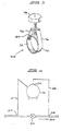
- an apparatus of the invention includes a vessel 10 which is formed of rigid plastics material sucn as polypropylene and which has a spherical shape. Three legs 11 are formed integrally with tne vessel 10 to support it on a level surface.
- the vessel 10 has an internally threaded outlet 12 into which is screwed a conduit leading to a manally operable ball valve 14 naving an operating handle 16.
- the vessel 10 Near to its highest point, the vessel 10 has a conventional, manually operable air release valve 18 which communicates with the interior of the vessel.
- a nipple 20 is screwed through the wall of the vesspl 10 near to its highest point and is of a conventional type suitable for confection of à flexible pressure line 21 leading from a process pipeline 52 (see Figures 6,7 and 9).
- the vessel 10 has an integral, externally threaded neck 22 onto which is screwed a cap 24 having an internal O-rirg seal and a nip d le 26 of the same type as the nipple 20.
- the nipple 26 has connected to it a flexible line 28 (see Figures 6,7 and 9) leading to the pipeline 52.
- a flexible bladder 30 formed of laminated PVC (polyvinyl chloride).
- the bladden is composed of a series of panels 32 which are heat-seamed to one another. Each panel is defined by edges of curvilinear shape and the bladder has patches 34,36 heat-seemed to the panels 32 at the points of convergence of the edges.
- the bladder When the bladder is full. it has a perfectly spherical shape.
- a space 38 surrounds the bladder when it is full in the vessel 10.
- a spigot 40 Communicating with the interior of the bladder through the upper patch 34 is a spigot 40 to which is fixed a hollow plug 42 having an annular recess accommodating an 0-ring seal 44,
- the upper end of the plug has a lip 46 which seats on the upper edge of the neck 22 with a chamfered surface 48 of the lip bearing against the O-ring seal 26.
- Figure 6 shows one application of the apparatus where continuous dosing of a liquid conveyed in a pipeline 52 by means of a dosant is to be carried out.
- the bladder 30 is filled with the dosant and the lines 21 and 28 are connected to the pipeline at points 54 and 56 upstream and downstream respectively of a manually operable valve 58.
- the direction of liquid flow in the pipeline is indicated in Figure 5 by the arrow 60.
- valve 58 If the valve 58 is partially closed, a pressure differential is created across the valve, with the upstream pressure being higher than the downstream pressure. Pressure liquid flows through the line 21 anc fills the space 38, exerting pressure on the bladder which gradually collapses it and expels its contents through the line 28 into the pipeline 52 downstream of the valve 58, The rate of dosing is proportional to the pressure differential, so by correctly setting the valve 58, the user is able to control the dosing rate accurately.
- the function of the air release valve 18 is to permit air to escape from the space 38 when liquid first flows into the space through the line 21.
- a manually operable gate valve or other conventional valve can be used for the valve 58.
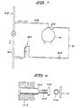
- a squeeze valve such as that seen in Figure 4.
- This valve includes a tube 62 of flexible material, such as silicon rubber.
- Two spaced, integral nipples 64,66 communicate with the tube 62.
- An annular squeezing device 68 is fitted about the tube 62 between the nipples 64 and 66.
- This device is seen in Figure 5 to include a single band 70 of stainless steel which is arranged tc form two loops 72 and 74.
- a screw 76 is threaded through a nut 78 fixed to the outer loop anc bears on a plate 80 fixed to the inner loop.
- the inner loop gets Smaller and smaller, at all times remaining circular in shape.
- the bore of the tube 62 beneath tne device 68 remains circular at all times, but is variable in diameter. Since the circular shape of the length 62 is maintained as the ciameter is varied, smooth laminar flow is also maintained, and hence there is a uniform pressure drop.
- the tube 62 is connected into the pipeline, and the lines 21 and 28 are connected up to the nipples 64 anc 66, respeetivaly.
- close control can be maintained over the dosing rate.
- Figure 7 shows another application of the apparatus where continuous dosinc takes place.
- a squeeze valve 58 of the Figure 4 type is again used to create the desired pressure differential, but there is also a conventional needle valve 82 associated with a rotameter 83 in the pressure line 21.
- the needle valve By appropriate setting of the needle valve, the flow rate in the pressure line can be controlled, and the rotameter enables an operator to determine the flow rate with accuracy.
- the apparatus of Figure 7 is identical to that of Figure 6. Note that the rotameter will also give an immediate indication if flow in the pipeline 52 should cease for any reason.
- the appropriate setting of the valve 58 will be made to achieve the correct dosing rate.
- an operator will be able to determine how long the apparatus can remain in operation before the contents of the bladder will have to be replenislied.
- the bladder will be refilled through the plug 42 once the outlet 12 has been opened to permit liquid to escace from the space 38.
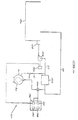
- FIG 9 illustrates one apparatus suitable for intermittent dosinc.
- a tank 86 holding a large volume of dosant liquid is connected to the nipple 20 via a line 88 cortro led by a sclenoid valve 90 which receives control signals from a microprccessor 92, The microprocessor 92 also sends control signals to solenoic valves 94, 96 located in the lines 21 and 28 and a solencig valve 98 controlling the outlet 12 form the vessel 10.
- a manually operable valve 58 of Figure 4 type is used to set the pressure reduction in the pipeline 52.
- valves 90 and 98 are closed. When a dosing cycle is completed, all valves are closed. When the bladder in the vessel 10 requires replenisnment, the valves 90 and 98 are opened and the other valves are closed. Water in the vessel 10 surrounding the bladder can run out of the vessel, and replenishment of the bladder takes place through the line 88. In each situation, the opening and closing of the various valves is controlled in accordance with a predetermined sequence, by the microprocessor 92.
- Figure 8 illustrates one form of solenoid valve suitable for use in this type of application.
- the solenoid valve has an armature 100 surrounded by a coil 102 whicn is energised or de-energised in accordance with signals from the microprocessor 92.
- the armature is drawn into the coil against the force of a compression spring 104 and, when it is de-energised, the spring urges the armature out of the coil so that a plate 106 at its end squepzes a flexible tube 108 connected intc the relevant line dgainst a ifxed plate 110.
- the tube 108 is formed of silicon rubber, and the spring force is chosen so that it will be overcome if line pressure should be excessive.
- valve 58 in Figure 9 could also be a solenoid or other valve which is adapted to be contrclled automatically in accordance with the predetermined cycle.
- FIG 10 illustrates schematically a chlorination system for a swimming pool 120.
- the pool 20 has an cverflow weir 122 from which water is drawn by a pump 124 driven by a motor 126. From the pump, the water is passed to a filter 128 after whicn it is returned to the pool.
- a chlorine dosing acparatus 130 is incorporated into the normal swimming pool water recirculation system.
- a pressure line 21 is connected to the process line 52 between the pump 124 and the filter 128, and proceeds to the vessel 10 of a dosing apparatus of the type described previously.
- the bladder 30 is filled with sodium hypochlorite solution at the correct ccncertration.
- the pressure drop across the filter causes the dosant liquid to be expelled into the line 52 downstream of the filter 128 at a rate depending on the pressure drop and on the setting of a solenoid valve 130 in the line 28.
- the setting of the solenoid valve 130 is controlled by the microprccesson
- the setting of the solenoid valve 130 is controlled by the microprocesson 132.
- the pump 124 is operated intermittently in accordance with a predetermined timing cycle.
- the microprocessor therefore includes a first timer unit 134 which receives a start-up signal from the motor 126 and which keeps the valve 130 closed until a precetermined time interval, sufficient to allow priming and pressurisation to take place, has passed. The valve is then opened for dosing tc commence.
- the microprocessor 132 also includes a second, manually adjustable timer unit 136 which takes over control of the solenoid valve to control opening and closing thereof in accordance with a predetermined sequence.
- a control unit 38 which can be actuated at the start of winter to halve the cosaqe.
- the microprocessor therefore includes a further control unit 140 which can be actuated to hold the solenoid valve 130 fully open for a pregetermined period sufficient to snock-dcse the pool.
- the pladder 30 should be of a material which is resistant to chemical attacx by the cosant PVC is a suitable material. Also, it should be possible for a small amount of reverse osmosis to take place between the interior of the ladder and the space 38, toinhibit algae growth in the space 36.
- the outlet 12 is positioned some distance above the lowest level of the vessel. It will, in fact, be above the level of the bottom end of the bladder 30 when the bladder is collapsed. With the outlet 12 so positioned, the vessel 10 will not be emptied completely during refilling operations, end the volume of liquid remaining in the vessel will provide some suppert to the bladder as it is refilled.
- An advantage of the invention over other types of dosing apparatus using venturis is the fact that it will dose efficiently even where there are very low liquid flow rates in the system supply line.
Landscapes
- Chemical & Material Sciences (AREA)
- Organic Chemistry (AREA)
- Health & Medical Sciences (AREA)
- Medicinal Chemistry (AREA)
- Life Sciences & Earth Sciences (AREA)
- Hydrology & Water Resources (AREA)
- Engineering & Computer Science (AREA)
- Environmental & Geological Engineering (AREA)
- Water Supply & Treatment (AREA)
- Chemical Kinetics & Catalysis (AREA)
- Nozzles (AREA)
- Feeding, Discharge, Calcimining, Fusing, And Gas-Generation Devices (AREA)
Applications Claiming Priority (2)
| Application Number | Priority Date | Filing Date | Title |
|---|---|---|---|
| ZA843488 | 1984-05-09 | ||
| ZA843488 | 1984-05-09 |
Publications (2)
| Publication Number | Publication Date |
|---|---|
| EP0164897A2 true EP0164897A2 (fr) | 1985-12-18 |
| EP0164897A3 EP0164897A3 (fr) | 1987-06-03 |
Family
ID=25577297
Family Applications (1)
| Application Number | Title | Priority Date | Filing Date |
|---|---|---|---|
| EP85303296A Withdrawn EP0164897A3 (fr) | 1984-05-09 | 1985-05-09 | Dispositif pour le dosage d'un liquide |
Country Status (3)
| Country | Link |
|---|---|
| EP (1) | EP0164897A3 (fr) |
| AU (1) | AU4222685A (fr) |
| ES (1) | ES8607462A1 (fr) |
Cited By (4)
| Publication number | Priority date | Publication date | Assignee | Title |
|---|---|---|---|---|
| US5582718A (en) * | 1994-06-14 | 1996-12-10 | Sobczak; Donald J. | Non-pressurized algaecide feeder method and apparatus for swimming pools and the like |
| CN101865359A (zh) * | 2010-06-24 | 2010-10-20 | 李慧岭 | 一种向管道内加注降尘剂的装置 |
| CN103452915A (zh) * | 2013-09-13 | 2013-12-18 | 侯康生 | 精密压差式加药装置 |
| CN115453135A (zh) * | 2022-09-22 | 2022-12-09 | 深圳大学 | 一种液体精确定量量取装置 |
Families Citing this family (4)
| Publication number | Priority date | Publication date | Assignee | Title |
|---|---|---|---|---|
| CN109607235B (zh) * | 2018-12-29 | 2021-07-13 | 航天神洁(北京)科技发展有限公司 | 一种带自循环的煤粉进料系统 |
| CN112138602A (zh) * | 2020-10-12 | 2020-12-29 | 李艳秋 | 一种尘土抑制剂加入装置 |
| CN112403142B (zh) * | 2020-10-28 | 2023-07-14 | 湖北众为钙业有限公司 | 一种压差式尘土抑制剂自主添加装置 |
| CN112439287A (zh) * | 2020-10-30 | 2021-03-05 | 李艳秋 | 一种压差式尘土抑制剂添加装置 |
Family Cites Families (5)
| Publication number | Priority date | Publication date | Assignee | Title |
|---|---|---|---|---|
| DE1242575B (de) * | 1962-02-20 | 1967-06-22 | Franz Ochmann | Anlage zum Impfen von durch Rohre geleitetem Wasser |
| DE1442636A1 (de) * | 1963-05-21 | 1970-01-08 | Julius Dopslaff | Dosiergeraet fuer loesliche,chemische Behandlungsmittel |
| US3928197A (en) * | 1970-11-30 | 1975-12-23 | Jacuzzi Bros Inc | Pollution control system for water supply |
| DE2629609C2 (de) * | 1976-07-01 | 1985-07-25 | R. und D. Rotter GmbH med.chem. Apparate- und Anlagenbau, 6086 Riedstadt | Zumischgerät |
| DE2636719C2 (de) * | 1976-08-14 | 1978-09-07 | Licentia Patent-Verwaltungs-Gmbh, 6000 Frankfurt | Einrichtung zum Zumischen von Zusatzstoffen in die Grenzschicht eines durch eine Hauptrohrleitung fließenden Wasserstromes |
-
1985
- 1985-05-09 ES ES542992A patent/ES8607462A1/es not_active Expired
- 1985-05-09 AU AU42226/85A patent/AU4222685A/en not_active Abandoned
- 1985-05-09 EP EP85303296A patent/EP0164897A3/fr not_active Withdrawn
Cited By (5)
| Publication number | Priority date | Publication date | Assignee | Title |
|---|---|---|---|---|
| US5582718A (en) * | 1994-06-14 | 1996-12-10 | Sobczak; Donald J. | Non-pressurized algaecide feeder method and apparatus for swimming pools and the like |
| CN101865359A (zh) * | 2010-06-24 | 2010-10-20 | 李慧岭 | 一种向管道内加注降尘剂的装置 |
| CN103452915A (zh) * | 2013-09-13 | 2013-12-18 | 侯康生 | 精密压差式加药装置 |
| CN103452915B (zh) * | 2013-09-13 | 2016-01-06 | 侯玥 | 精密压差式加药装置 |
| CN115453135A (zh) * | 2022-09-22 | 2022-12-09 | 深圳大学 | 一种液体精确定量量取装置 |
Also Published As
| Publication number | Publication date |
|---|---|
| ES8607462A1 (es) | 1986-06-01 |
| EP0164897A3 (fr) | 1987-06-03 |
| ES542992A0 (es) | 1986-06-01 |
| AU4222685A (en) | 1985-11-14 |
Similar Documents
| Publication | Publication Date | Title |
|---|---|---|
| US3867290A (en) | Apparatus for chemical treatment of swimming pools | |
| US4588396A (en) | Apparatus for gravity feed of liquid under constant hydrostatic pressure | |
| US5468066A (en) | Apparatus and method for injecting dry particulate material in a fluid flow line | |
| EP0008925B1 (fr) | Appareil intercalé pour faire dissoudre une matière solide dans un liquide | |
| US4955507A (en) | Orange juice dispensing system | |
| CN100586492C (zh) | 向透析单元供应透析流体的方法及装置 | |
| US3626972A (en) | Soluble granule feeders | |
| ZA929881B (en) | Process for supplying preset quantities of liquids, particularly viscous liquids, and apparatus for using the same | |
| US5582718A (en) | Non-pressurized algaecide feeder method and apparatus for swimming pools and the like | |
| US5881753A (en) | Passive fluid level controller | |
| US3204633A (en) | Volumetric automatic shut-off fluid valve for infusion apparatus | |
| US5353957A (en) | Apparatus and method for controlled dispensing of a liquid | |
| US3468809A (en) | Method and apparatus for dissolving a slightly soluble substance in a liquid | |
| US4363728A (en) | Automatic chlorinator for swimming pools | |
| EP0266202A1 (fr) | Système pour distribuer du jus | |
| EP0570326B1 (fr) | Appareil de distribution de liquide et méthode | |
| US3220435A (en) | Apparatus for metering a medicant into stock watering system | |
| JPH08511468A (ja) | 濃縮物希釈システム | |
| US6453927B1 (en) | Method and apparatus for precisely dispensing liquids | |
| US4509863A (en) | Apparatus for mixing milk with flavoring and fluoride | |
| Burke et al. | A simplified flow-through apparatus for maintaining fixed concentrations of toxicants in water | |
| US3204661A (en) | Apparatus for proportioning and delivering fluids | |
| US3638837A (en) | Proportioning and cleaning device | |
| CA1092359A (fr) | Dispositif d'injection de produits chimiques | |
| RU2059401C1 (ru) | Устройство для приготовления и выдачи коктейля с применением газов, биологически активных веществ и пенообразователей |
Legal Events
| Date | Code | Title | Description |
|---|---|---|---|
| PUAI | Public reference made under article 153(3) epc to a published international application that has entered the european phase |
Free format text: ORIGINAL CODE: 0009012 |
|
| AK | Designated contracting states |
Designated state(s): DE FR GB |
|
| PUAL | Search report despatched |
Free format text: ORIGINAL CODE: 0009013 |
|
| AK | Designated contracting states |
Kind code of ref document: A3 Designated state(s): DE FR GB |
|
| STAA | Information on the status of an ep patent application or granted ep patent |
Free format text: STATUS: THE APPLICATION IS DEEMED TO BE WITHDRAWN |
|
| 18D | Application deemed to be withdrawn |
Effective date: 19871202 |
|
| RIN1 | Information on inventor provided before grant (corrected) |
Inventor name: WILLOWS, REGINALD |