EP0164968A1 - Geschmierte Hochgeschwindigkeitslageranordnung - Google Patents
Geschmierte Hochgeschwindigkeitslageranordnung Download PDFInfo
- Publication number
- EP0164968A1 EP0164968A1 EP85303843A EP85303843A EP0164968A1 EP 0164968 A1 EP0164968 A1 EP 0164968A1 EP 85303843 A EP85303843 A EP 85303843A EP 85303843 A EP85303843 A EP 85303843A EP 0164968 A1 EP0164968 A1 EP 0164968A1
- Authority
- EP
- European Patent Office
- Prior art keywords
- bearing unit
- bearing
- separators
- lubricant
- rotary bodies
- Prior art date
- Legal status (The legal status is an assumption and is not a legal conclusion. Google has not performed a legal analysis and makes no representation as to the accuracy of the status listed.)
- Withdrawn
Links
- 239000000314 lubricant Substances 0.000 claims abstract description 40
- 230000001050 lubricating effect Effects 0.000 claims abstract description 9
- 230000000694 effects Effects 0.000 claims abstract description 5
- 230000015572 biosynthetic process Effects 0.000 claims abstract description 4
- 230000003746 surface roughness Effects 0.000 claims description 11
- 238000005461 lubrication Methods 0.000 claims description 9
- 238000010276 construction Methods 0.000 claims description 7
- 239000002131 composite material Substances 0.000 claims description 6
- 229910052751 metal Inorganic materials 0.000 claims description 6
- 239000002184 metal Substances 0.000 claims description 6
- 239000000463 material Substances 0.000 claims description 5
- 230000002093 peripheral effect Effects 0.000 claims description 3
- 239000012858 resilient material Substances 0.000 claims description 3
- 230000005465 channeling Effects 0.000 claims description 2
- 230000008878 coupling Effects 0.000 claims 1
- 238000010168 coupling process Methods 0.000 claims 1
- 238000005859 coupling reaction Methods 0.000 claims 1
- 230000005540 biological transmission Effects 0.000 abstract description 14
- 238000005096 rolling process Methods 0.000 description 10
- 238000011161 development Methods 0.000 description 5
- 229910000760 Hardened steel Inorganic materials 0.000 description 3
- 239000011248 coating agent Substances 0.000 description 3
- 238000000576 coating method Methods 0.000 description 3
- BQCADISMDOOEFD-UHFFFAOYSA-N Silver Chemical compound [Ag] BQCADISMDOOEFD-UHFFFAOYSA-N 0.000 description 2
- 230000001133 acceleration Effects 0.000 description 2
- 239000010687 lubricating oil Substances 0.000 description 2
- 230000000717 retained effect Effects 0.000 description 2
- 229910052709 silver Inorganic materials 0.000 description 2
- 239000004332 silver Substances 0.000 description 2
- 125000006850 spacer group Chemical group 0.000 description 2
- 238000012360 testing method Methods 0.000 description 2
- 230000007423 decrease Effects 0.000 description 1
- 235000003642 hunger Nutrition 0.000 description 1
- 238000012423 maintenance Methods 0.000 description 1
- 238000000034 method Methods 0.000 description 1
- 238000012986 modification Methods 0.000 description 1
- 230000004048 modification Effects 0.000 description 1
- 238000013021 overheating Methods 0.000 description 1
- 238000007747 plating Methods 0.000 description 1
- 238000000926 separation method Methods 0.000 description 1
- 239000007787 solid Substances 0.000 description 1
- 230000037351 starvation Effects 0.000 description 1
Images



Classifications
-
- F—MECHANICAL ENGINEERING; LIGHTING; HEATING; WEAPONS; BLASTING
- F16—ENGINEERING ELEMENTS AND UNITS; GENERAL MEASURES FOR PRODUCING AND MAINTAINING EFFECTIVE FUNCTIONING OF MACHINES OR INSTALLATIONS; THERMAL INSULATION IN GENERAL
- F16C—SHAFTS; FLEXIBLE SHAFTS; ELEMENTS OR CRANKSHAFT MECHANISMS; ROTARY BODIES OTHER THAN GEARING ELEMENTS; BEARINGS
- F16C33/00—Parts of bearings; Special methods for making bearings or parts thereof
- F16C33/30—Parts of ball or roller bearings
- F16C33/37—Loose spacing bodies
- F16C33/3706—Loose spacing bodies with concave surfaces conforming to the shape of the rolling elements, e.g. the spacing bodies are in sliding contact with the rolling elements
-
- F—MECHANICAL ENGINEERING; LIGHTING; HEATING; WEAPONS; BLASTING
- F16—ENGINEERING ELEMENTS AND UNITS; GENERAL MEASURES FOR PRODUCING AND MAINTAINING EFFECTIVE FUNCTIONING OF MACHINES OR INSTALLATIONS; THERMAL INSULATION IN GENERAL
- F16C—SHAFTS; FLEXIBLE SHAFTS; ELEMENTS OR CRANKSHAFT MECHANISMS; ROTARY BODIES OTHER THAN GEARING ELEMENTS; BEARINGS
- F16C19/00—Bearings with rolling contact, for exclusively rotary movement
- F16C19/02—Bearings with rolling contact, for exclusively rotary movement with bearing balls essentially of the same size in one or more circular rows
- F16C19/20—Bearings with rolling contact, for exclusively rotary movement with bearing balls essentially of the same size in one or more circular rows with loose spacing bodies, e.g. balls, between the bearing balls
-
- F—MECHANICAL ENGINEERING; LIGHTING; HEATING; WEAPONS; BLASTING
- F16—ENGINEERING ELEMENTS AND UNITS; GENERAL MEASURES FOR PRODUCING AND MAINTAINING EFFECTIVE FUNCTIONING OF MACHINES OR INSTALLATIONS; THERMAL INSULATION IN GENERAL
- F16C—SHAFTS; FLEXIBLE SHAFTS; ELEMENTS OR CRANKSHAFT MECHANISMS; ROTARY BODIES OTHER THAN GEARING ELEMENTS; BEARINGS
- F16C19/00—Bearings with rolling contact, for exclusively rotary movement
- F16C19/22—Bearings with rolling contact, for exclusively rotary movement with bearing rollers essentially of the same size in one or more circular rows, e.g. needle bearings
- F16C19/40—Bearings with rolling contact, for exclusively rotary movement with bearing rollers essentially of the same size in one or more circular rows, e.g. needle bearings with loose spacing bodies between the rollers
-
- F—MECHANICAL ENGINEERING; LIGHTING; HEATING; WEAPONS; BLASTING
- F16—ENGINEERING ELEMENTS AND UNITS; GENERAL MEASURES FOR PRODUCING AND MAINTAINING EFFECTIVE FUNCTIONING OF MACHINES OR INSTALLATIONS; THERMAL INSULATION IN GENERAL
- F16C—SHAFTS; FLEXIBLE SHAFTS; ELEMENTS OR CRANKSHAFT MECHANISMS; ROTARY BODIES OTHER THAN GEARING ELEMENTS; BEARINGS
- F16C33/00—Parts of bearings; Special methods for making bearings or parts thereof
- F16C33/30—Parts of ball or roller bearings
- F16C33/38—Ball cages
- F16C33/44—Selection of substances
- F16C33/445—Coatings
-
- F—MECHANICAL ENGINEERING; LIGHTING; HEATING; WEAPONS; BLASTING
- F16—ENGINEERING ELEMENTS AND UNITS; GENERAL MEASURES FOR PRODUCING AND MAINTAINING EFFECTIVE FUNCTIONING OF MACHINES OR INSTALLATIONS; THERMAL INSULATION IN GENERAL
- F16C—SHAFTS; FLEXIBLE SHAFTS; ELEMENTS OR CRANKSHAFT MECHANISMS; ROTARY BODIES OTHER THAN GEARING ELEMENTS; BEARINGS
- F16C33/00—Parts of bearings; Special methods for making bearings or parts thereof
- F16C33/30—Parts of ball or roller bearings
- F16C33/66—Special parts or details in view of lubrication
- F16C33/6637—Special parts or details in view of lubrication with liquid lubricant
- F16C33/6681—Details of distribution or circulation inside the bearing, e.g. grooves on the cage or passages in the rolling elements
-
- F—MECHANICAL ENGINEERING; LIGHTING; HEATING; WEAPONS; BLASTING
- F16—ENGINEERING ELEMENTS AND UNITS; GENERAL MEASURES FOR PRODUCING AND MAINTAINING EFFECTIVE FUNCTIONING OF MACHINES OR INSTALLATIONS; THERMAL INSULATION IN GENERAL
- F16H—GEARING
- F16H57/00—General details of gearing
- F16H57/04—Features relating to lubrication or cooling or heating
- F16H57/0456—Lubrication by injection; Injection nozzles or tubes therefor
-
- F—MECHANICAL ENGINEERING; LIGHTING; HEATING; WEAPONS; BLASTING
- F16—ENGINEERING ELEMENTS AND UNITS; GENERAL MEASURES FOR PRODUCING AND MAINTAINING EFFECTIVE FUNCTIONING OF MACHINES OR INSTALLATIONS; THERMAL INSULATION IN GENERAL
- F16H—GEARING
- F16H57/00—General details of gearing
- F16H57/04—Features relating to lubrication or cooling or heating
- F16H57/048—Type of gearings to be lubricated, cooled or heated
- F16H57/0482—Gearings with gears having orbital motion
-
- F—MECHANICAL ENGINEERING; LIGHTING; HEATING; WEAPONS; BLASTING
- F16—ENGINEERING ELEMENTS AND UNITS; GENERAL MEASURES FOR PRODUCING AND MAINTAINING EFFECTIVE FUNCTIONING OF MACHINES OR INSTALLATIONS; THERMAL INSULATION IN GENERAL
- F16C—SHAFTS; FLEXIBLE SHAFTS; ELEMENTS OR CRANKSHAFT MECHANISMS; ROTARY BODIES OTHER THAN GEARING ELEMENTS; BEARINGS
- F16C2361/00—Apparatus or articles in engineering in general
- F16C2361/61—Toothed gear systems, e.g. support of pinion shafts
-
- F—MECHANICAL ENGINEERING; LIGHTING; HEATING; WEAPONS; BLASTING
- F16—ENGINEERING ELEMENTS AND UNITS; GENERAL MEASURES FOR PRODUCING AND MAINTAINING EFFECTIVE FUNCTIONING OF MACHINES OR INSTALLATIONS; THERMAL INSULATION IN GENERAL
- F16H—GEARING
- F16H57/00—General details of gearing
- F16H57/04—Features relating to lubrication or cooling or heating
- F16H57/042—Guidance of lubricant
- F16H57/043—Guidance of lubricant within rotary parts, e.g. axial channels or radial openings in shafts
-
- F—MECHANICAL ENGINEERING; LIGHTING; HEATING; WEAPONS; BLASTING
- F16—ENGINEERING ELEMENTS AND UNITS; GENERAL MEASURES FOR PRODUCING AND MAINTAINING EFFECTIVE FUNCTIONING OF MACHINES OR INSTALLATIONS; THERMAL INSULATION IN GENERAL
- F16H—GEARING
- F16H57/00—General details of gearing
- F16H57/04—Features relating to lubrication or cooling or heating
- F16H57/0467—Elements of gearings to be lubricated, cooled or heated
- F16H57/0479—Gears or bearings on planet carriers
Definitions
- This invention relates to a high speed lubricated bearing unit and in the preferred embodiment provides a bearing unit for high load applications such as encountered in jet engines, electrical power generating systems, and planetary gearing arrangements.
- a high speed lubricated bearing unit comprising: inner and outer coaxial members forming respective inner and outer raceways separated by an annular gap; a plurality of spaced rotary bodies engaged in the raceways in an annular array in said gap; and a plurality of free floating separators alternately disposed within the array between each of the rotary bodies, said separators each having a concave bearing contact surface on each of its peripheral sides within the array slidingly engaging its respective adjacent rotary body in a generally contiguous fashion to maintain a predetermined spacing between the rotary bodies within the array, and each of said bearing surfaces having a radius of curvature greater than the radius of curvature of its respective adjacent rotary body and at least one radially extending groove for channeling lubricant during use of the bearing unit between the bearing surface and said rotary body to form a lubricant film of a predetermined minimum thickness between the separators and the rotary bodies.
- the preferred embodiments of the invention provide bearing units which promote the development of an elastohydrodynamic or EHD lubricating film between the various elements of the bearing units to facilitate use in high load applications.
- the preferred bearing unit includes inner and outer coaxial rings forming respective inner and outer raceways separated by an annular gap, and a plurality of rotary bodies engaged in the raceways alternately disposed with a plurality of wedge-shaped separators in an annular array within the gap to maintain a predetermined spacing between the rotary bodies.
- Each of the separators is formed with concave bearing surfaces which slidingly engage their respective adjacent rotary bodies, and at least one radially extending lubricating groove is provided in each of the bearing surfaces to channel lubricant from the inner raceway to accommodate the formation of an EHD lubricating film of a predetermined thickness between the bearing surfaces and the rotary bodies.
- This arrangement has been found to essentially eliminate lubricant starvation between the sliding surfaces of the bearing unit, while at the same time minimizing frictional losses within the unit. This of course can be extremely important when the bearing units are used in electrical power generating systems and the like where reliability and efficiency are imperative for economic operation of the system.
- the preferred embodiments of the invention are relatively inexpensive and easily fabricated. Specifically, by effecting the formation of an EHD lubricating film between the sliding components of the bearing unit, rougher surface finishes can be used on the sliding elements of the bearing unit than has been the case with the bearing units heretofore available. This has been found to significantly enhance the service life of the bearing unit while at the same time simplifying its repair and replacement.
- a preferred embodiment of the invention provides separators of a resilient material to absorb and dampen impact loading between the rotary bodies during use. Such loading will typically be encountered as a result of the constant acceleration and deceleration of the rotary bodies when the bearing unit is used to support an orbiting shaft in a planetary transmission or the like. This in turn reduces wear and fatigue of the rotary bodies and thus similarly enhances the reliability and service life of the unit.
- the preferred embodiments of the invention provide high speed bearing units which have proven to be particularly reliable and efficient in high load applications such as encountered in jet engines, power generating systems, and related planetary gearing arrangements.
- the bearing unit is of a relatively inexpensive, straight-forward and easily manufactured construction; however, it is to be understood that numerous other advantages and features of the invention will become readily apparent from the following description, claims, and drawings of various embodiments of the invention.
- the high speed lubricated bearing unit 1 embodying the invention is shown in a planetary gearing apparatus or transmission 2.
- the transmission 2 is adapted for use in the drive train interconnecting a steam turbine to an electrical generator in an electrical power generating system.
- this particular use of the bearing unit 1 is merely illustrative of one application of the invention and is not intended to limit the invention to this specific embodiment.
- the transmission 2 is housed within a generally cylindrical, vertically split casing 3 formed of frustocon- ical-ly shaped inboard and outboard segments 4 and 5 secured together as generally indicated at 6 in the drawings.
- an input shaft 7 is mounted within the inboard segment 4 for rotation along the axis 8 of the transmission 2 which is adapted to be coupled to the steam turbine via spline gear 9, and an output shaft 10 is similarly mounted for rotation within a bearing 11 carried by the outboard casing segment 5.
- suitable planetary gearing 12 the output speed of the transmission 2 can be designed to match the speed required for a particular generator load.
- the planetary gearing 12 includes a carrier assembly 13 which is mounted for rotation about the axis 8 on a pair of roller bearings 14 and 15 carried by the inboard casing segment 4 and the output shaft 10, respectively.
- the carrier assembly 13 in turn supports and carries three planetary gear shafts 16 which are symetrically disposed about the axis 8 and are rotatably supported at each of their ends by one of the bearing units 1 secured within the carrier assembly 13.
- a star gear 17 is provided on the end of the input shaft 7 which meshes with a first planetary gear 18 on each of the planetary.gear shafts 16 which in turn meshes with a stationary ring gear 19 secured to the inboard casing segment 4.
- the planetary gear shafts 16 are in turn connected to the output shaft 10 through a second planetary gear 20 on each of the gear shafts 16 which meshes with a rotatable ring gear 21 secured to the output shaft 10 through suitable splined joints 22 and 23 to complete the gear train through the transmission.
- the bearing units 1 In addition to this loading the bearing units 1 must also carry the g loads created by the rotation of the planetary gear shafts 16 about their own axis which in this case is about 6500 rpm. Thus, the resultant g loading on each of the bearing units 1 typically oscillates between about 550 and 1350 g's during operation of the transmission.
- each of the bearing units 1 is provided with inner and outer coaxial rings 30 and 31 forming respective inner and outer raceways 32 and 33 separated by_an annular gap 34.
- the outer rings 31 are secured in a suitable bore or aperture 35 at each end of the carrier assembly 13, and the inner rings 30 are integrally formed in the ends of the planetary gear shafts 16, although it is to be understood that the inner rings 30 can also be fabricated as entirely separate members which can be secured about the ends of the gear shafts 16.
- a plurality of hollow crowned hardened steel rollers 36 are engaged in the raceways 32 and 33 in an annular array within the gap 34, and a plurality of free floating spacers or separators 37 of a generally wedge-shaped configuration are disposed within the array between each of the rollers 36.
- Each of the separators 37 has a radially outwardly convex outer surface 38 slidingly engaged in the outer raceway 33, and a concave bearing contact surface 39 on each of its peripherial sides which slidingly engages its respective adjacent roller 36 in a generally contiguous fashion to maintain a predetermined spacing between the rollers 36 within the array.
- both the rollers 36 and the separators 37 are axially retained-within the-bearing unit 1 by a pair of inwardly projecting rims or lodgements 40 formed in the outer ring 31. Additionally, for reasons which will be discussed, it should be noted that each of the separators 37 is plated with a silver coating or other suitable material which is softer than the hardened steel rollers 36.
- each of the separators 37 is formed so that the radius of curvature R l of the outer surface 38 is slightly less than the radius R2 of the outer raceway 33, and the radius R3 of the rollers 36 is slightly less than the radius of curvature R4 of each of the contact surfaces 39.
- R l was about 2.9100 in., R2 2.9115 in., R3 0.4920 in. and R4 0.5040 in. while the grooves 41 were formed to extend entirely across the contact surface 39 at a depth of slightly more than 0.01 in.
- this structure maintains separation of the rollers and provides guidance in a true circular sense for the separators as they move along the outer raceway while essentially assuring adequate lubrication of the bearing unit during high speed operations.
- the invention provides for directing lubricant into the bearing units .1 through a plurality of ports or passages 42 extending through the inner rings 30 which open into the inner raceways 32.
- lubricant is conducted from a pressurized lubricant reservoir 43 through a series of passages 110, 111, 112, 113, and 114 in the transmission 2 and injected through nozzles or orifices 115 into the hollow interiors 45 of each end of the planetary gear shafts 16 where centrifugal force causes the lubricant to flow through the passages 42 into the inner raceways 32 to lubricate the bearing units 1.
- the invention contemplates a fairly wide range of surface finishes for the various elements of the bearing unit.
- the RMS of the composite surface roughness should preferably be no greater than about 17 x 10 -6 in.
- the RMS of the surface roughness of one element was 12 x 10 -6 in.
- the RMS of the the surface roughness of the other element should be about 12 x 10- 6 in.
- the RMS of the surface roughness of one of the elements could easily be finished to 6 x 10 -6 in.
- the other element could simply be finished to a rougher but more easily fabricated and less expensive finish having an RMS of 16 x 10- 6 in. while still maintaining 100 percent lubrication within the bearing unit.
- the invention calls for coating each of the separators 37 with a silver plating or other suitable material which is softer than the hardened steel rollers 36. Testing has indicated this provides a self-lubricating coating which essentially eliminates the possibility of the bearing elements overheating or scoring during start-up or shut-down operations.
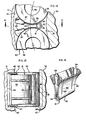
- Figures 8-10 show a second embodiment of the invention wherein a bearing unit 50 is provided with a plurality of free floating separators 51 disposed between a plurality of crowned rollers 36 engaged in the raceways 32 and 33, it being noted that in these and subsequent drawings elements corresponding to those shown in Figs. 1-7 are identified by the same numerals.
- Each of the separators 51 is of a generally wedge-shaped configuration having a radially outwardly convex outer surface 52 slidingly engaged in the outer raceway 33, and a concave bearing contact surface 53 on each of its peripheral sides which slidingly engages its respective adjacent roller 36 in a generally contiguous fashion to maintain a predetermined spacing between the rollers 36 within the array.
- a pair of parallel grooves 54 are formed in each of the bearing surfaces 53 to channel lubricant between the separators and the rollers.
- both the rollers 36 and the separators 51 are axially retained within the bearing unit 50 by the inwardly projecting rims or lodgements 40.formed in the outer ring 31.
- each of the separators 51 is formed so that its respective bearing contact surfaces 53 embrace the rollers 36 radially inwardly and outwardly of the path followed by the center of the rollers 36 as they move about the inner raceway 32 as generally illustrated by the phantom line 55 in Fig. 8.
- This structure provides a means of radially entrapping each of the rollers 36 between the opposing portions of the bearing surfaces as indicated at 56 and 70 to secure the rollers within the assembly. This is accomplished by initially forming the separator 51 with parallel tabs 58 separated by a slot 59 as shown in phantom lines in Fig. 8 and then assemblying the bearing unit. After this is accomplished the tabs 58 are bent outwardly to the position shown in solid lines to secure the separators 51 and the rollers 36 within the assembly. This arrangement results in the bearing unit 50 functioning in essentially the same fashion as a bearing having a single piece cage.
- the separators 51 are formed so the minimum spacing between the rollers 36 exists approximately halfway between the inner and outer raceways 32 and 33. This configuration has been found to reduce the radially directed loads on the separators during use of the bearing unit which in turn reduces the frictional losses between the outer surfaces 52 and the outer raceway 33.
- Figs. 11-13 show a third embodiment of the invention wherein a bearing unit 70 is provided with a separator 71 which is completely isolated from the outer raceway 33.
- This arrangement obviously does not incur any significant frictional losses between the separator 71 and the outer raceway 33.
- each of the separators 71 is formed so that its respective concave bearing contact surfaces 72 embrace the rollers 36 radially inwardly and outwardly of the path followed by the center of the rollers 36 as they move about the inner race 32 as indicated by the phantom line 55 in Fig.-11, and with an outer edge portion 73 spaced radially inward from the outer raceway 33 positioned between the inwardly projecting lodgements 40.
- This structure effectively entraps and secures the rollers 36 and the separators 71 within the assembly.
- each of the separators 71 are provided with a pair of parallel lubricating grooves 74 in each of its bearing contact surfaces 72.
- a plurality of lubricant passages 75 are provided in the separator which accommodate the flow of lubricant into the grooves 74 from a generally v-shaped lubricant collecting zone 76 formed in the inner surface of the separator. This structure serves to collect and channel lubricant thrown off the inner raceway to the bearing surfaces during use of the bearing unit, thereby effectively assuring its complete lubrication.
- Figs. 14-16 show a fourth embodiment of the invention wherein a bearing unit 80 is provided with a separator 81 formed of a relatively lightweight sheet metal construction.
- the separator 81 is formed so that its respective concave bearing contact surfaces 82 embrace the rollers 36 radially inwardly and outwardly of the path followed by the center of the rollers 36 as they move about the inner raceway 32 as generally illustrated by the phantom line 55 in Fig. 14.
- a pair of radially extending, parallel lubricating grooves 87 are formed in each of the bearing contact surfaces 82 to accommodate the development of an EHD lubricating film between the rollers and the separators.
- each of the separators 81 is provided with a pair of spaced leaf portions 83 having projecting outer edge or ear portions 84 at their distal ends disposed between the lodgements 40.
- This structure effectively entraps and secures the rollers 36 and the separators 81 within the assembly.
- the sheet metal construction utilized for the separator 81 has been found to be particularly desirable because it tends to dampen and abate loads on the rollers such as those resulting from the constant acceleration and deceleration of the rollers encountered when the bearing unit is used to support an orbiting shaft in a planetary transmission or the like.
- the invention calls for interconnecting the spaced leaf portions 83 with a resilient central connecting portion 85 formed by wrapping a single sheet of metal forming the leaf portions 83 around a compressible split tube 86.
- This arrangement accommodates momentary deflection of the leaf portions 83 to dissipate predetermined impact loads on the bearing surfaces 82 by the rollers 36, and, in the event of greater impact loading, the split tube 86 is similarly momentarily compressed to dissipate those loads.
- the entire separator 81 is fabricated from metal components. However, it is to be understood that other materials may be used provided they possess the necessary resilient properties as will be readily apparent to one skilled in the materials and bearing arts.
- Figs. 17-19 illustrate a fifth embodiment of the invention wherein a ball bearing unit 90 is provided with separators 91.
- Each of the ball bearing units 90 includes inner and outer coaxial rings 92 and 93 forming respective inner and outer raceways 94 and 95 separated by an annular gap 96.
- a plurality of spherical ball bearings 97 are engaged in the raceways 94 and 95 in a spaced annular array within the gap 96, and a plurality of free floating separators 91 are disposed within the array between each of the ball bearings 97.
- each of the separators 91 is formed of a relatively lightweight resilient sheet metal construction having a pair of spaced leaf portions 98 interconnected by a connecting portion 99 defining concave bearing surfaces 100 which engage the balls 97 in a generally contiguous fashion to retain the ball bearings and the separators within the assembly.
- a pair of radially extending parallel grooves 103 are formed in each of the bearing surfaces 100 to channel lubricant onto the bearing surfaces to effect an EHD lubricant film between the ball bearings and the separators.
- each of the leaf portions 98 is provided with a pair of outwardly projecting feet or slippers 101 which are adapted to slide along the inner faces 102 of the inner ring 92 to prevent twisting or turning of the separators 91 within the assembly during use.
- the separators 91 promote the development and maintenance of an EHD film between the ball bearings and the separators to accommodate use of the bearing unit in high speed applications while at the same time utilizing a resilient construction which dampens and dissipates impact loading between the ball bearings.
- any of the foregoing embodiments can be used to retain ball bearings, as well as rollers, provided of course that suitable modifications are made as will be readily apparent to one skilled in the bearing arts.
Landscapes
- Engineering & Computer Science (AREA)
- General Engineering & Computer Science (AREA)
- Mechanical Engineering (AREA)
- Rolling Contact Bearings (AREA)
Applications Claiming Priority (2)
| Application Number | Priority Date | Filing Date | Title |
|---|---|---|---|
| US61654984A | 1984-06-01 | 1984-06-01 | |
| US616549 | 1984-06-01 |
Publications (1)
| Publication Number | Publication Date |
|---|---|
| EP0164968A1 true EP0164968A1 (de) | 1985-12-18 |
Family
ID=24469954
Family Applications (1)
| Application Number | Title | Priority Date | Filing Date |
|---|---|---|---|
| EP85303843A Withdrawn EP0164968A1 (de) | 1984-06-01 | 1985-05-31 | Geschmierte Hochgeschwindigkeitslageranordnung |
Country Status (2)
| Country | Link |
|---|---|
| EP (1) | EP0164968A1 (de) |
| JP (1) | JPS60263726A (de) |
Cited By (23)
| Publication number | Priority date | Publication date | Assignee | Title |
|---|---|---|---|---|
| FR2601735A1 (fr) * | 1986-07-16 | 1988-01-22 | Skf France | Dispositif de roue libre a cames du type a autocentrage a paliers |
| GB2192952A (en) * | 1986-06-13 | 1988-01-27 | Bonfiglioli Trasmital Spa | Bearing assembly for a wheel |
| EP0666966B1 (de) * | 1992-10-31 | 1996-06-12 | INA Wälzlager Schaeffler KG | Radialwälzlager |
| EP1961982A4 (de) * | 2005-12-16 | 2010-10-27 | Ntn Toyo Bearing Co Ltd | Rollenlager |
| EP2420702A1 (de) * | 2010-08-19 | 2012-02-22 | Robert Bosch GmbH | Druckölschmierung der Zahnräder eines Planetengetriebes |
| CN102374282A (zh) * | 2010-08-19 | 2012-03-14 | 罗伯特·博世有限公司 | 行星齿轮变速器的齿轮压力油润滑 |
| US8523451B2 (en) | 2005-09-01 | 2013-09-03 | Ntn Corporation | Roller bearing |
| WO2015091165A3 (de) * | 2013-12-19 | 2015-08-20 | Aktiebolaget Skf | Wälzlagerkäfig oder -käfigelement |
| WO2016011126A1 (en) * | 2014-07-17 | 2016-01-21 | Baldor Electric Company | Vertical gear motor planetary gear lubrication system |
| EP2559913A4 (de) * | 2010-04-13 | 2016-06-15 | Kawasaki Heavy Ind Ltd | Planetengetriebevorrichtung |
| EP2390520A3 (de) * | 2010-05-27 | 2016-08-17 | Jtekt Corporation | Rollenlager |
| US9528594B2 (en) | 2014-09-04 | 2016-12-27 | Baldor Electric Company | Lubrication system for a gear box and associated methods |
| US9528596B2 (en) | 2014-08-06 | 2016-12-27 | Baldor Electric Company | Gear box with clutch having spring engagement and hydraulic disengagement |
| US9797499B2 (en) | 2014-08-12 | 2017-10-24 | Baldor Electric Company | Method of installing a motor on a gear box |
| DE102016222455A1 (de) * | 2016-11-16 | 2018-05-17 | Schaeffler Technologies AG & Co. KG | Planetengetriebe, insbesondere Stirnraddifferentialgetriebe oder Reduktionsvorstufe hierzu |
| DE102018219011B3 (de) * | 2018-11-08 | 2020-02-13 | Zf Friedrichshafen Ag | Schmierstoffversorgung eines Planetengleitlagers |
| DE102018219140A1 (de) * | 2018-11-09 | 2020-05-14 | Zf Friedrichshafen Ag | Verzweigte Schmierstoffleitung |
| WO2020148200A1 (en) * | 2019-01-18 | 2020-07-23 | Aktiebolaget Skf | High precision gear box |
| DE102019212444A1 (de) * | 2019-08-20 | 2021-02-25 | Zf Friedrichshafen Ag | Schmierstoffversorgung eines Planetengleitlagers II |
| FR3128752A1 (fr) * | 2021-10-29 | 2023-05-05 | Safran Transmission Systems | Déflecteur d’huile amélioré pour réducteur mécanique de turbomachine d’aéronef |
| US12092200B1 (en) * | 2023-08-23 | 2024-09-17 | Allison Transmission, Inc. | Lubrication of a planetary gear system |
| US20250215930A1 (en) * | 2024-01-02 | 2025-07-03 | Aktiebolaget Skf | Toroid separator with lubricant channels for ball bearings |
| US12492727B2 (en) | 2024-01-02 | 2025-12-09 | Aktiebolaget Skf | Low wear toroid separator for ball bearings |
Families Citing this family (3)
| Publication number | Priority date | Publication date | Assignee | Title |
|---|---|---|---|---|
| JPH0236622U (de) * | 1988-09-02 | 1990-03-09 | ||
| JP4884886B2 (ja) * | 2005-09-01 | 2012-02-29 | Ntn株式会社 | ころ軸受 |
| JP2007205455A (ja) * | 2006-02-01 | 2007-08-16 | Nsk Ltd | 転がり軸受 |
Citations (9)
| Publication number | Priority date | Publication date | Assignee | Title |
|---|---|---|---|---|
| DE255713C (de) * | ||||
| DE499378C (de) * | 1930-06-14 | G & J Jaeger A G | Rollenlager | |
| DE523480C (de) * | 1931-04-24 | G & J Jaeger Akt Ges | Rollenlager | |
| GB740703A (en) * | 1952-11-14 | 1955-11-16 | Rolls Royce | Improvements in or relating to bearings |
| FR1215359A (fr) * | 1958-02-13 | 1960-04-19 | Thew Shovel Co | Pièce d'écartement pour roulement à billes |
| US2969267A (en) * | 1956-10-23 | 1961-01-24 | Skf Svenska Kullagerfab Ab | Cage for rolling bodies in rolling bearings |
| CH416228A (de) * | 1963-03-28 | 1966-06-30 | Zaugg Werner | Wälzlager |
| US3782795A (en) * | 1972-04-06 | 1974-01-01 | Timken Co | Tapered roller bearing |
| FR2355201A1 (fr) * | 1976-06-16 | 1978-01-13 | Daimler Benz Ag | Piece d'ecartement spherique mobile d'un roulement a billes d'un assemblage par vis |
-
1985
- 1985-05-31 JP JP11867285A patent/JPS60263726A/ja active Pending
- 1985-05-31 EP EP85303843A patent/EP0164968A1/de not_active Withdrawn
Patent Citations (9)
| Publication number | Priority date | Publication date | Assignee | Title |
|---|---|---|---|---|
| DE255713C (de) * | ||||
| DE499378C (de) * | 1930-06-14 | G & J Jaeger A G | Rollenlager | |
| DE523480C (de) * | 1931-04-24 | G & J Jaeger Akt Ges | Rollenlager | |
| GB740703A (en) * | 1952-11-14 | 1955-11-16 | Rolls Royce | Improvements in or relating to bearings |
| US2969267A (en) * | 1956-10-23 | 1961-01-24 | Skf Svenska Kullagerfab Ab | Cage for rolling bodies in rolling bearings |
| FR1215359A (fr) * | 1958-02-13 | 1960-04-19 | Thew Shovel Co | Pièce d'écartement pour roulement à billes |
| CH416228A (de) * | 1963-03-28 | 1966-06-30 | Zaugg Werner | Wälzlager |
| US3782795A (en) * | 1972-04-06 | 1974-01-01 | Timken Co | Tapered roller bearing |
| FR2355201A1 (fr) * | 1976-06-16 | 1978-01-13 | Daimler Benz Ag | Piece d'ecartement spherique mobile d'un roulement a billes d'un assemblage par vis |
Cited By (37)
| Publication number | Priority date | Publication date | Assignee | Title |
|---|---|---|---|---|
| GB2192952A (en) * | 1986-06-13 | 1988-01-27 | Bonfiglioli Trasmital Spa | Bearing assembly for a wheel |
| GB2192952B (en) * | 1986-06-13 | 1990-10-24 | Bonfiglioli Trasmital Spa | Integrated bearing for reduction elements |
| FR2601735A1 (fr) * | 1986-07-16 | 1988-01-22 | Skf France | Dispositif de roue libre a cames du type a autocentrage a paliers |
| EP0666966B1 (de) * | 1992-10-31 | 1996-06-12 | INA Wälzlager Schaeffler KG | Radialwälzlager |
| US8523451B2 (en) | 2005-09-01 | 2013-09-03 | Ntn Corporation | Roller bearing |
| EP1961982A4 (de) * | 2005-12-16 | 2010-10-27 | Ntn Toyo Bearing Co Ltd | Rollenlager |
| US7963702B2 (en) | 2005-12-16 | 2011-06-21 | Ntn Corporation | Roller bearing |
| EP2559913A4 (de) * | 2010-04-13 | 2016-06-15 | Kawasaki Heavy Ind Ltd | Planetengetriebevorrichtung |
| EP2390520A3 (de) * | 2010-05-27 | 2016-08-17 | Jtekt Corporation | Rollenlager |
| EP2420702A1 (de) * | 2010-08-19 | 2012-02-22 | Robert Bosch GmbH | Druckölschmierung der Zahnräder eines Planetengetriebes |
| US8840508B2 (en) | 2010-08-19 | 2014-09-23 | Robert Bosch Gmbh | Pressure oil lubrication of the gear wheels of a planetary gear set |
| CN102374282A (zh) * | 2010-08-19 | 2012-03-14 | 罗伯特·博世有限公司 | 行星齿轮变速器的齿轮压力油润滑 |
| CN102374282B (zh) * | 2010-08-19 | 2016-02-10 | 罗伯特·博世有限公司 | 行星齿轮变速器的齿轮压力油润滑 |
| WO2015091165A3 (de) * | 2013-12-19 | 2015-08-20 | Aktiebolaget Skf | Wälzlagerkäfig oder -käfigelement |
| CN105829744A (zh) * | 2013-12-19 | 2016-08-03 | 斯凯孚公司 | 滚动轴承保持架或保持架元件 |
| US9850948B2 (en) | 2013-12-19 | 2017-12-26 | Aktiebolaget Skf | Rolling bearing cage or cage element |
| CN105829744B (zh) * | 2013-12-19 | 2019-06-28 | 斯凯孚公司 | 滚动轴承保持架或保持架元件 |
| US9416866B2 (en) | 2014-07-17 | 2016-08-16 | Baldor Electric Company | Vertical gear motor planetary gear lubrication system |
| WO2016011126A1 (en) * | 2014-07-17 | 2016-01-21 | Baldor Electric Company | Vertical gear motor planetary gear lubrication system |
| CN106662237B (zh) * | 2014-07-17 | 2019-08-13 | Abb电机和机械公司 | 立式齿轮马达行星齿轮润滑系统 |
| CN106662237A (zh) * | 2014-07-17 | 2017-05-10 | 葆德电气公司 | 立式齿轮马达行星齿轮润滑系统 |
| US9528596B2 (en) | 2014-08-06 | 2016-12-27 | Baldor Electric Company | Gear box with clutch having spring engagement and hydraulic disengagement |
| US9797499B2 (en) | 2014-08-12 | 2017-10-24 | Baldor Electric Company | Method of installing a motor on a gear box |
| US9528594B2 (en) | 2014-09-04 | 2016-12-27 | Baldor Electric Company | Lubrication system for a gear box and associated methods |
| DE102016222455A1 (de) * | 2016-11-16 | 2018-05-17 | Schaeffler Technologies AG & Co. KG | Planetengetriebe, insbesondere Stirnraddifferentialgetriebe oder Reduktionsvorstufe hierzu |
| DE102016222455B4 (de) | 2016-11-16 | 2018-11-29 | Schaeffler Technologies AG & Co. KG | Planetengetriebe, insbesondere Stirnraddifferentialgetriebe oder Reduktionsvorstufe hierzu |
| DE102018219011B3 (de) * | 2018-11-08 | 2020-02-13 | Zf Friedrichshafen Ag | Schmierstoffversorgung eines Planetengleitlagers |
| US11493124B2 (en) | 2018-11-09 | 2022-11-08 | Zf Friedrichshafen Ag | Branched lubricant line |
| DE102018219140A1 (de) * | 2018-11-09 | 2020-05-14 | Zf Friedrichshafen Ag | Verzweigte Schmierstoffleitung |
| WO2020148200A1 (en) * | 2019-01-18 | 2020-07-23 | Aktiebolaget Skf | High precision gear box |
| CN113302415A (zh) * | 2019-01-18 | 2021-08-24 | 斯凯孚公司 | 高精度齿轮箱 |
| DE102019212444A1 (de) * | 2019-08-20 | 2021-02-25 | Zf Friedrichshafen Ag | Schmierstoffversorgung eines Planetengleitlagers II |
| FR3128752A1 (fr) * | 2021-10-29 | 2023-05-05 | Safran Transmission Systems | Déflecteur d’huile amélioré pour réducteur mécanique de turbomachine d’aéronef |
| US12092200B1 (en) * | 2023-08-23 | 2024-09-17 | Allison Transmission, Inc. | Lubrication of a planetary gear system |
| US20250215930A1 (en) * | 2024-01-02 | 2025-07-03 | Aktiebolaget Skf | Toroid separator with lubricant channels for ball bearings |
| US12492727B2 (en) | 2024-01-02 | 2025-12-09 | Aktiebolaget Skf | Low wear toroid separator for ball bearings |
| US12607225B2 (en) * | 2024-01-02 | 2026-04-21 | Aktiebolaget Skf | Toroid separator with lubricant channels for ball bearings |
Also Published As
| Publication number | Publication date |
|---|---|
| JPS60263726A (ja) | 1985-12-27 |
Similar Documents
| Publication | Publication Date | Title |
|---|---|---|
| EP0164968A1 (de) | Geschmierte Hochgeschwindigkeitslageranordnung | |
| US4641977A (en) | Bearing system | |
| US6095940A (en) | Traction drive transmission | |
| US4428628A (en) | High speed, durable roller bearing | |
| US4384749A (en) | Reliability roller bearing | |
| US20130077907A1 (en) | Bearing oiling system | |
| US4167860A (en) | Universal joint | |
| JP3744663B2 (ja) | ラジアル玉軸受用保持器及びラジアル玉軸受 | |
| RU2232926C2 (ru) | Подшипник качения | |
| EP2189673B1 (de) | Wälzkörperlager | |
| US4874260A (en) | Cage outer diameter profile | |
| US3549222A (en) | High speed anti-friction bearing | |
| US6196721B1 (en) | Sinusoidal viscous interface for attenuation of vibration for ball and roller bearings | |
| CN1100220C (zh) | 油脂润滑锥形滚柱轴承 | |
| WO1994024446A1 (en) | Self-pumping roller bearings | |
| JPH07259864A (ja) | ころ軸受及び円錐ころ軸受並びに自動調心ころ軸受 | |
| JPH02221715A (ja) | 玉軸受用の保持器 | |
| KR920008191B1 (ko) | 구름베아링 | |
| US10544834B1 (en) | Bearing for use in high speed application | |
| CN112728017B (zh) | 减速器 | |
| US20050064979A1 (en) | Bevel gear transmission | |
| EP3683465B1 (de) | Lager zur verwendung in einer hochgeschwindigkeitsanwendung | |
| US4799807A (en) | Rolling bearing with rolling retainers | |
| RU14060U1 (ru) | Опора вала | |
| WO1984004141A1 (en) | Bearing system |
Legal Events
| Date | Code | Title | Description |
|---|---|---|---|
| PUAI | Public reference made under article 153(3) epc to a published international application that has entered the european phase |
Free format text: ORIGINAL CODE: 0009012 |
|
| AK | Designated contracting states |
Designated state(s): DE FR GB |
|
| 17P | Request for examination filed |
Effective date: 19860618 |
|
| 17Q | First examination report despatched |
Effective date: 19870601 |
|
| STAA | Information on the status of an ep patent application or granted ep patent |
Free format text: STATUS: THE APPLICATION IS DEEMED TO BE WITHDRAWN |
|
| 18D | Application deemed to be withdrawn |
Effective date: 19871013 |
|
| RIN1 | Information on inventor provided before grant (corrected) |
Inventor name: HAMBRIC, JAMES CLEMENT |