EP0165078A2 - Bremsblockiergerät - Google Patents
Bremsblockiergerät Download PDFInfo
- Publication number
- EP0165078A2 EP0165078A2 EP85304336A EP85304336A EP0165078A2 EP 0165078 A2 EP0165078 A2 EP 0165078A2 EP 85304336 A EP85304336 A EP 85304336A EP 85304336 A EP85304336 A EP 85304336A EP 0165078 A2 EP0165078 A2 EP 0165078A2
- Authority
- EP
- European Patent Office
- Prior art keywords
- plunger
- passage
- camshaft
- piston
- locking device
- Prior art date
- Legal status (The legal status is an assumption and is not a legal conclusion. Google has not performed a legal analysis and makes no representation as to the accuracy of the status listed.)
- Withdrawn
Links
- 238000007789 sealing Methods 0.000 claims abstract description 8
- 238000011144 upstream manufacturing Methods 0.000 claims description 8
- 230000015572 biosynthetic process Effects 0.000 claims description 7
- 230000006835 compression Effects 0.000 claims description 4
- 238000007906 compression Methods 0.000 claims description 4
- 230000002457 bidirectional effect Effects 0.000 claims description 3
- 230000013011 mating Effects 0.000 claims description 2
- 239000012530 fluid Substances 0.000 abstract description 11
- 238000009434 installation Methods 0.000 abstract 1
- 238000005755 formation reaction Methods 0.000 description 4
- 230000009977 dual effect Effects 0.000 description 2
- 210000002445 nipple Anatomy 0.000 description 2
- 238000000034 method Methods 0.000 description 1
- 238000012986 modification Methods 0.000 description 1
- 230000004048 modification Effects 0.000 description 1
- 238000005086 pumping Methods 0.000 description 1
Images


Classifications
-
- B—PERFORMING OPERATIONS; TRANSPORTING
- B60—VEHICLES IN GENERAL
- B60T—VEHICLE BRAKE CONTROL SYSTEMS OR PARTS THEREOF; BRAKE CONTROL SYSTEMS OR PARTS THEREOF, IN GENERAL; ARRANGEMENT OF BRAKING ELEMENTS ON VEHICLES IN GENERAL; PORTABLE DEVICES FOR PREVENTING UNWANTED MOVEMENT OF VEHICLES; VEHICLE MODIFICATIONS TO FACILITATE COOLING OF BRAKES
- B60T17/00—Component parts, details, or accessories of power brake systems not covered by groups B60T8/00, B60T13/00 or B60T15/00, or presenting other characteristic features
- B60T17/08—Brake cylinders other than ultimate actuators
- B60T17/16—Locking of brake cylinders
-
- B—PERFORMING OPERATIONS; TRANSPORTING
- B60—VEHICLES IN GENERAL
- B60R—VEHICLES, VEHICLE FITTINGS, OR VEHICLE PARTS, NOT OTHERWISE PROVIDED FOR
- B60R25/00—Fittings or systems for preventing or indicating unauthorised use or theft of vehicles
- B60R25/01—Fittings or systems for preventing or indicating unauthorised use or theft of vehicles operating on vehicle systems or fittings, e.g. on doors, seats or windscreens
- B60R25/08—Fittings or systems for preventing or indicating unauthorised use or theft of vehicles operating on vehicle systems or fittings, e.g. on doors, seats or windscreens operating on brakes or brake systems
Definitions
- THIS invention relates to a brake locking device.
- the type of device here under consideration is one which is installed in a brake fluid supply line between the master cylinder and slave or brake cylinders of a motor vehicle.
- Such devices include a non-return valve which, at least when operational, permits brake fluid to flow from the master to the brake cylinders, but which prevents flow in the opposite direction.
- the brakes of the vehicle can be applied, but cannot be released until the non-return valve is actuated to resume its original condition.
- An object of the present invention is to provide a brake locking device which, when operational, only permits unidirectional flow of brake fluid to the brake cylinders and which incorporates a novel form of non-return valve.
- the invention provides a brake locking device comprising a housing having a first passage therein, at least one second passage therein intersecting the first passage at a right angle, upstream and downstream ports entering the second passage to either side of a shoulder in that passage and being respectively communicable with a brake master cylinder and a brake cylinder, a camshaft rotatable in the first passage and carrying a cam opposite the second passage, a plunger located in the second passage and movable axially in sealing relationship with the second passage by the cam, a plunger piston mating with the plunger in axial sliding relationship, a closure formation on the piston, and biasing means urging the piston apart from the plunger, the arrangement being such that, on rotation of the camshaft to a first, operative position, the plunger is moved by the cam and the closure is urged by the biasing means to seat on the shoulder to act as a non-return valve permitting unidirectional flow through the second passage from the upstream to the downstream port but preventing return flow, and, on rotation of the cams
- the piston is arranged as an axial slide fit in a blind bore in the plunger.
- the piston carries an 0-ring, the 0-ring abutting a collar on the piston and constituting the closure formation, the biasing means being in the form of a compression spring acting between the plunger and the collar.
- Stop means may be provided to ensure that the spring cannot bias the 0-ring into sealing engagement with the shoulder when the camshaft is rotated to its second, inoperative position.
- the stop means can take the form of a lateral projection on the piston which abuts an abutment on the plunger when the camshaft is rotated to its second, inoperative position.
- the piston carries a transverse, laterally projecting pin and the plunger is formed with a lateral bore intersecting the blind bore which receives the piston, the pin abutting the wall of the lateral bore when the camshaft is rotated to its second, inoperative position.
- Alarm means may be provided for indicating to a driver of a vehicle fitted with the device that the camshaft is in the first, operative position at least when an attempt is made to start the vehicle's engine.
- There may be a port communicating with the first passage through which are inserted spaced terminals of an electrical circuit including the ignition switch of the vehicle and an alarm device, and a formation on the camshaft which bridges the terminals to complete the circuit and energise the alarm device when the ignition switch is switched on.
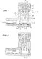
- the device illustrated in the Figures includes a body 10 made up of two parts 12 and 14 which are held together by cap screws 16 located in deep bores 18 in the body part 12. Once the body parts have been assembled correctly, the bores 18 are plugged up behind the cap screws to prevent their removal and unauthorised tampering with the interior components.
- Two parallel passages 28 extend in the body part 12 from near its upper end right to its lower end, where they intersect, at 90°, a passage 3 0 formed in the body part 14. Each of the passages 28 accommodates a plunger and piston assembly, the nature of which is illustrated more clearly in Figure 7.
- Each plunger and piston assembly comprises two parts, a plunger 31 and a plunger piston 32.
- the plunger carries two 0-rings 34 encircling its mid-section and is formed with a blind bore 36 receiving the plunger piston 32 in an axial slide fit.
- a compression spring 38 acts between the end of the plunger and a collar 40 on the plunger piston.
- the plunger piston has an axial bore 42 which intersects a transverse bore 44 passing right through the piston and there is, in addition, a further transverse bore 46 passing right through the piston.
- An 0-ring 48 encircles the piston next to the collar.
- the 0-rings 34 are sized to make a good sealing fit in the passage 28.
- Each passage has the shape shown, with a major portion 52 of its length having a greater diameter than a minor portion 54 and with a shoulder 53 between the portions 52 and 54.
- Formed in the body part 12 from each side thereof are two threaded ports 56 and 58 which vent into the passages 28 a short distance apart from one another.
- the upstream port 56 receives a threaded nipple connected to a conduit leading from the master cylinder of a vehicle's hydraulic brake system, and the downstream port 58 a threaded nipple connected to a conduit leading to the brake cylinders of, say, the front wheel pair.
- the conduits will be connected up to both sets of ports 56 and 58.
- a camshaft 60 fitted with a cam lobe 62 located opposite the passages 28. Also accommodated within the passage 30, and protruding slightly from its open end is a lock 66 which is connected to the rear end of the camshaft 60 by a screw 59. When the correct key 67 is inserted into the lock and rotated, the camshaft and hence the cam lobes are rotated.
- Figure 4 illustrates the nature of the camshaft and lock in greater detail, with Figures 5 and 6 illustrating the shape of the cam lobe.
- the open end of the passage 30 is plugged securely by means of a plug 68.
- the device described above operates in the following way, assuming that only a single plunger and piston assembly is used i.e. one of the passages 28 is empty :
- pressurised brake fluid from the master cylinder enters the portion 54 of the passage 28 via the port 56.
- the pressure fluid fills the space existing in the portion 54 about the upper end of the plunger piston 32 and applies a downward force to unseat the 0-ring 48 from the shoulder 53 against the bias of the spring 38.
- the fluid is then able to flow through the passage 28 to the port 58 from where it flows to the brake cylinder(s) to actuate the brakes.
- Pressure fluid downstream of the device is unable to return through the device because, at pressure equalisation, the spring 38 urges the 0-ring 48 back into sealing engagement with the shoulder 53.
- the 0-ring serves as the closure in a non-return valve when the device is in this condition.
- the driver can now withdraw the key 67 leaving the device in the Figure 1, operative condition, in which the vehicle cannot be driven. Note that it is not essential for the driver to go through the brake pedal pumping procedure. He can, if he wishes, merely withdraw the key once the device has been set in the Figure 1 condition. Then, if a would-be thief attempts to drive the vehicle away, he will get no further than the place at which he first applies pressure to the brake pedal, because the situation described above will take place.
- Brake fluid is therefore capable of bidirectional flow between the master and brake cylinders and the vehicle's brakes will operate in the normal way.
- an alarm facility can be provided in a relatively simple manner. It will be seen in Figures 1 and 2 that vertical holes 72 extend from the underside of the part 14 to the passage 30 accommodating the camshaft.
- electrical leads in an electrical alarm circuit are arranged to extend into the passage 30 through one or both holes 72.
- the camshaft will be shaped in its regions opposite the holes 72 so as to contact both leads when the device is in the Figure 1 condition, so completing the electrical circuit.
- the circuit includes the ignition switch of the vehicle as well as an audible or visible alarm device in the cab of the vehicle.
- the alarm circuit is completed by the bridging action of the camshaft and an audible or visible signal is emitted in the cab to warn him not to drive until he has used the key 67 to return the device to the Figure 2 condition.
- a further switch device could conveniently be located in the space occupied in Figure 1 and 2 by an end plug 68 closing off the passage 30 with suitable formations at the end of the camshaft to actuate the switch on rotation of the camshaft.
- This further switch device could form part of an electrical alarm circuit including an externally audible alarm device to indicate to passers-by that an unauthorised person is making an attempt to drive away the vehicle without first having returned the brake locking device to the Figure 2 condition.
- the brake locking device described above will normally be mounted behind the dashboard of the vehicle with the keyhole of the lock 66 in an easily accessible position.
- Other places for the device are, of course, also possibilities eg under the bonnet.
Landscapes
- Engineering & Computer Science (AREA)
- Mechanical Engineering (AREA)
- Transportation (AREA)
- Regulating Braking Force (AREA)
- Transmission Of Braking Force In Braking Systems (AREA)
- Braking Arrangements (AREA)
Applications Claiming Priority (2)
| Application Number | Priority Date | Filing Date | Title |
|---|---|---|---|
| ZA844545 | 1984-06-15 | ||
| ZA844545 | 1984-06-15 |
Publications (2)
| Publication Number | Publication Date |
|---|---|
| EP0165078A2 true EP0165078A2 (de) | 1985-12-18 |
| EP0165078A3 EP0165078A3 (de) | 1986-12-30 |
Family
ID=25577352
Family Applications (1)
| Application Number | Title | Priority Date | Filing Date |
|---|---|---|---|
| EP85304336A Withdrawn EP0165078A3 (de) | 1984-06-15 | 1985-06-17 | Bremsblockiergerät |
Country Status (1)
| Country | Link |
|---|---|
| EP (1) | EP0165078A3 (de) |
Cited By (1)
| Publication number | Priority date | Publication date | Assignee | Title |
|---|---|---|---|---|
| GB2270547A (en) * | 1992-09-14 | 1994-03-16 | Derek Salter | Vehicle anti theft device |
Family Cites Families (4)
| Publication number | Priority date | Publication date | Assignee | Title |
|---|---|---|---|---|
| DE936550C (de) * | 1953-12-04 | 1955-12-15 | P Alfred Kurdewan | Druckfluessigkeits-Standbremse fuer Kraftfahrzeuge |
| GB897622A (en) * | 1959-10-20 | 1962-05-30 | Douglas Sangster Duncan | Locking device on hydraulic brakes to prevent theft of automobiles |
| US3653730A (en) * | 1970-01-27 | 1972-04-04 | Dejan O Cvetkovich | Wheel lock for a vehicle |
| DE7830800U1 (de) * | 1977-10-18 | 1982-10-21 | Panetta, Domenico, Cesano Boscone, Milano | Steuerelement für eine Diebstahlsicherung für Kraftfahrzeuge |
-
1985
- 1985-06-17 EP EP85304336A patent/EP0165078A3/de not_active Withdrawn
Cited By (1)
| Publication number | Priority date | Publication date | Assignee | Title |
|---|---|---|---|---|
| GB2270547A (en) * | 1992-09-14 | 1994-03-16 | Derek Salter | Vehicle anti theft device |
Also Published As
| Publication number | Publication date |
|---|---|
| EP0165078A3 (de) | 1986-12-30 |
Similar Documents
| Publication | Publication Date | Title |
|---|---|---|
| US3515442A (en) | Lock for hydraulic brakes of vehicles | |
| US5375684A (en) | Brake release lock | |
| US3174502A (en) | Theft prevention apparatus | |
| US3625573A (en) | Antithief devices | |
| US4040675A (en) | Anti-theft vehicle brake-supervising device | |
| US4633686A (en) | Anti-theft brake lock | |
| US4765362A (en) | Anti-theft system for vehicles | |
| US5570756A (en) | Anti-theft system for immobilizing a vehicle | |
| US3617663A (en) | Antitheft lock for vehicle brakes and ignition system | |
| US3998495A (en) | Locking dashboard control valve | |
| EP0505767B1 (de) | Vorrichtung zum Blockieren eines Hydraulik- oder Druckluftkreises eines Fahrzeuges, insbesondere Bremskreises oder dergleichen | |
| HK1010049B (en) | Device for locking a hydraulic or pneumatic circuit of a vehicle, such as a braking circuit or the like | |
| EP0165078A2 (de) | Bremsblockiergerät | |
| US4928506A (en) | Anti-theft locking valve for motor vehicles | |
| US4964677A (en) | Vehicle anti-theft system | |
| US3579285A (en) | Hydraulic antitheft system for vehicles | |
| EP0253431B1 (de) | Diebstahlsicherungssystem für Fahrzeuge | |
| US5392876A (en) | Anti-theft method and device for automotive vehicles | |
| US20070284943A1 (en) | RF-immobilizer and contactless ignition for a motor vehicle | |
| US5335758A (en) | Anti-theft vehicle brake supervising device | |
| GB2118653A (en) | Vehicle immobilisation device | |
| US3871402A (en) | Automatic transmission fluid control apparatus | |
| GB2283289A (en) | Immobilising valve for a vehicle hydraulic brake circuit | |
| CA1268638A (en) | Antitheft device for automotive vehicles | |
| GB745875A (en) | Hydraulic brake device for vehicles |
Legal Events
| Date | Code | Title | Description |
|---|---|---|---|
| PUAI | Public reference made under article 153(3) epc to a published international application that has entered the european phase |
Free format text: ORIGINAL CODE: 0009012 |
|
| AK | Designated contracting states |
Designated state(s): AT BE CH DE FR GB IT LI LU NL SE |
|
| PUAL | Search report despatched |
Free format text: ORIGINAL CODE: 0009013 |
|
| AK | Designated contracting states |
Kind code of ref document: A3 Designated state(s): AT BE CH DE FR GB IT LI LU NL SE |
|
| 17P | Request for examination filed |
Effective date: 19870629 |
|
| 17Q | First examination report despatched |
Effective date: 19881019 |
|
| STAA | Information on the status of an ep patent application or granted ep patent |
Free format text: STATUS: THE APPLICATION IS DEEMED TO BE WITHDRAWN |
|
| 18D | Application deemed to be withdrawn |
Effective date: 19890629 |