EP0165337A2 - Palier de bras pour un store à bras articulés - Google Patents
Palier de bras pour un store à bras articulés Download PDFInfo
- Publication number
- EP0165337A2 EP0165337A2 EP84112012A EP84112012A EP0165337A2 EP 0165337 A2 EP0165337 A2 EP 0165337A2 EP 84112012 A EP84112012 A EP 84112012A EP 84112012 A EP84112012 A EP 84112012A EP 0165337 A2 EP0165337 A2 EP 0165337A2
- Authority
- EP
- European Patent Office
- Prior art keywords
- threaded bolt
- arm
- pin
- arm bearing
- webs
- Prior art date
- Legal status (The legal status is an assumption and is not a legal conclusion. Google has not performed a legal analysis and makes no representation as to the accuracy of the status listed.)
- Granted
Links
Images

Classifications
-
- E—FIXED CONSTRUCTIONS
- E04—BUILDING
- E04F—FINISHING WORK ON BUILDINGS, e.g. STAIRS, FLOORS
- E04F10/00—Sunshades, e.g. Florentine blinds or jalousies; Outside screens; Awnings or baldachins
- E04F10/02—Sunshades, e.g. Florentine blinds or jalousies; Outside screens; Awnings or baldachins of flexible canopy materials, e.g. canvas ; Baldachins
- E04F10/06—Sunshades, e.g. Florentine blinds or jalousies; Outside screens; Awnings or baldachins of flexible canopy materials, e.g. canvas ; Baldachins comprising a roller-blind with means for holding the end away from a building
- E04F10/0666—Accessories
- E04F10/0674—Accessories acting as separate supporting bar
-
- E—FIXED CONSTRUCTIONS
- E04—BUILDING
- E04F—FINISHING WORK ON BUILDINGS, e.g. STAIRS, FLOORS
- E04F10/00—Sunshades, e.g. Florentine blinds or jalousies; Outside screens; Awnings or baldachins
- E04F10/02—Sunshades, e.g. Florentine blinds or jalousies; Outside screens; Awnings or baldachins of flexible canopy materials, e.g. canvas ; Baldachins
- E04F10/06—Sunshades, e.g. Florentine blinds or jalousies; Outside screens; Awnings or baldachins of flexible canopy materials, e.g. canvas ; Baldachins comprising a roller-blind with means for holding the end away from a building
- E04F10/0611—Sunshades, e.g. Florentine blinds or jalousies; Outside screens; Awnings or baldachins of flexible canopy materials, e.g. canvas ; Baldachins comprising a roller-blind with means for holding the end away from a building with articulated arms supporting the movable end of the blind for deployment of the blind
- E04F10/0618—Sunshades, e.g. Florentine blinds or jalousies; Outside screens; Awnings or baldachins of flexible canopy materials, e.g. canvas ; Baldachins comprising a roller-blind with means for holding the end away from a building with articulated arms supporting the movable end of the blind for deployment of the blind whereby the pivot axis of the articulation is perpendicular to the roller
-
- E—FIXED CONSTRUCTIONS
- E04—BUILDING
- E04F—FINISHING WORK ON BUILDINGS, e.g. STAIRS, FLOORS
- E04F10/00—Sunshades, e.g. Florentine blinds or jalousies; Outside screens; Awnings or baldachins
- E04F10/02—Sunshades, e.g. Florentine blinds or jalousies; Outside screens; Awnings or baldachins of flexible canopy materials, e.g. canvas ; Baldachins
- E04F10/06—Sunshades, e.g. Florentine blinds or jalousies; Outside screens; Awnings or baldachins of flexible canopy materials, e.g. canvas ; Baldachins comprising a roller-blind with means for holding the end away from a building
- E04F10/0637—Sunshades, e.g. Florentine blinds or jalousies; Outside screens; Awnings or baldachins of flexible canopy materials, e.g. canvas ; Baldachins comprising a roller-blind with means for holding the end away from a building with mechanisms for adjusting the inclination of the blind
Definitions
- the invention relates to an arm bearing for an articulated arm awning, in which a support bracket can be clamped on a square support tube and pivots and locks a bearing bracket about an axis parallel to the support tube.
- Such an articulated arm awning which is built on a square support tube, has been very well preserved due to its stable construction.
- the arm bearings are clamped on the square support tube.
- these arm bearings In order for the inclination of the articulated arms to be adjustable, these arm bearings must be designed to be pivotable about the axis of the square support tube. This generally requires complex constructions with concentric ring arrangements.
- the adjustment of the inclination is complex because several screw connections have to be loosened. After loosening the screw connections, the articulated arms are adjusted. The entire arrangement is very unstable, so this setting requires great skill. Finally the screw connections have to be tightened again.
- the object of the invention is to provide an arm support which can be adjusted in a simple manner using a tool which is available at all times and which has high stability, in particular torsional rigidity.
- the trestle is designed as a bracket, one leg of which has two parallel webs and a crossbar connecting them at the ends, that a trunnion in eyes protruding over the center web is approximately opposite the webs for receiving the Bearing block is provided that the bearing block articulates a threaded bolt lying between the webs and that the threaded bolt in a thread engages sleeve which is rotatably arranged in a receptacle of the crossbar.
- the arm bearing according to the invention differs from the prior art in a manner that is not obvious, since the inclination can be adjusted by turning a threaded bolt in a threaded sleeve. This rotation can be done with a key-like tool.
- the screwing arrangement of the threaded bolt in the threaded sleeve is self-locking, so that it is not necessary to secure the setting.
- the inclination can be adjusted at any time. The inclination is clearly defined at all times, even during the adjustment.
- the setting of the respective arm bearing is secured. A swivel range of up to 45 ° to the horizontal is possible without difficulty.
- the arm bearing has a very stable construction. It consists of a forked, angular arrangement.
- the pedestal is received between the eyes of the trestle and is therefore protected against canting even when subjected to strong forces, in particular transverse forces.
- the threaded bolt lies between the webs in a channel or slot.
- a stable design and increase in the torsional rigidity is obtained by the fact that a pin sits in the eyes of the bearing block for the articulated reception of the threaded bolt and that the threaded bolt extends approximately in the middle between the two webs of the leg.
- One type of arrangement of the threaded bolt is characterized in that the pin receives an eye of the threaded bolt.
- the assembly is facilitated in that the bearing block perpendicular to the passage for the pin has a passage for the head of the threaded bolt and also has a recess following the passage for pivoting the head.
- the invention provides that a disc spring is arranged between an end face of the polygonal approach and the crossbar.
- the securing of the adjusting device against unintentional adjustment or against jumping out of the guides is improved in that the receptacle of the crossbar is designed as a semi-cylindrical groove, that the threaded sleeve has contact flanges on both ends of a tubular part, which bear against the end faces of the groove, and that A guide passage for the threaded bolt is provided in the crosspiece. Even in the event of sudden loads on the awning caused by wind forces or the like, the arm bearing cannot inadvertently adjust or deflect. Damage to the awning is therefore excluded.
- the arm bearing is fixed to the square support tube in that passages for screw connections are provided at the ends of the webs, which engage in the opposite leg and tighten the trestle on the square support tube.
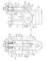
- An articulated arm awning according to the invention has a square support tube 1 which is held in brackets 2 which can be fastened to the wall or another support.
- the square support tube 1 represents the supporting element for the construction of the entire awning.
- Supporting blocks 3 are clamped onto the square supporting tube, each of which supports a bearing block 4 with a passage 23 for mounting a swivel arm 6
- a support bracket 3 and a bearing bracket 4 each form an arm bearing 5. Normally there are two arm bearings.
- the sheet ⁇ is fastened to the drop bar 7, which on the other hand is wound on a sheet shaft 9.
- the cloth shaft 9 is supported in bearing blocks 10, which are also seated on the square support tube 1.
- the drive elements for the fabric shaft 9 are not shown.
- the support bracket 3 of the arm support 5 is designed as a bracket.
- a leg 11, a central web 12 and a further leg 13 encompass the square support tube 1.
- the leg 13 comprises two webs 14 which run parallel to one another and which are connected to one another at the ends by a cross web 15. As a result, a groove 17 or a slot is formed between the webs 14.
- a passage 16 is provided in the crosspiece 15 and is aligned with the channel 17 between the webs 14.
- Two eyes 18 protrude from the central web 12 and also form guide walls.
- passages 19 are formed which are aligned with passages 20 in the leg 11. These passages serve to receive screw connections 21 or other tensioning devices, which are indicated schematically in FIG. 2 and serve to firmly clamp the support bracket 3 on the square support tube 1.
- the eyes 18 receive a support pin 22 on which the bearing block 4 is pivotably seated.
- the bearing block 4 is guided between the guide walls of the eyes 18 and on the stable support pin 22 so as to prevent jamming.
- the bearing block 4 is a substantially right-angled part and has at the front end a passage 23 for receiving a bearing pin (not shown) for a swivel arm 6.
- two eyes 24 are formed opposite one another, which receive a pin 25.
- An eye 26 of a threaded bolt 27 is pivotably seated on the pin 25.
- the threaded bolt 27 extends approximately parallel to the webs 14 within the slot or the channel 17.
- the threaded bolt 27 engages with a threaded section 32 in a threaded sleeve 2 Q , which is located inside of the passage 16 is located.
- the threaded sleeve 28 has a polygonal projection 29, which enables the threaded sleeve 29 to be rotated.
- a plate spring 31 Between an end face of the polygonal shoulder 29 and the end face of the cross bar 15 there is a plate spring 31 which generates an additional clamping force and frictional force.
- the threaded sleeve At the other end is the threaded sleeve through a lake gerring 30 secured in the axial direction.
- the outer diameter of the threaded sleeve 28 is smaller than the inner diameter of the passage 16 so that the threaded sleeve 28 can move and adjust within the passage. Since the threaded sleeve 28 is secured against displacement in both directions of movement, the articulated arms of the awning are thereby held stable, so that the awning cannot swing up.
- the bearing block 4 is pivoted about the support pin 22.
- the friction in the components and additional due to the plate spring is so great that an unintentional adjustment is not possible.
- the bearing block 4 can be adjusted in a very simple manner by turning the polygonal projection 29.
- the inclination of the articulated arms and thus the inclination of the awning can be adjusted accordingly. It has been shown that the pivoting range of over 45 ° with respect to the horizontal that can be achieved by the arm bearing according to the invention is completely sufficient in practice.
- the user can adjust the inclination with an open-ended wrench. There is no need to loosen any fasteners.
- the inclination can be adjusted in every extended state of the awning and is clearly defined in every condition so that the inclination of the awning cannot be changed unintentionally.
- the threaded bolt 27 is protected between the webs 14 against harmful effects.
- the bearing block is guided laterally in its entire pivoting area through the guide walls of the eyes 18 and is thus secured against tilting. An inadmissible load on the trunnion 22 is avoided.
- the stable construction and the mutual guidance of the elements ensure high torsional rigidity.
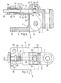
- the bearing block 4 has a passage 52 in the head part 51 for the pin 65.
- the pin 65 in turn has a transverse passage 66 which receives the threaded bolt 67.
- the threaded bolt 67 has a head 70 which abuts the pin 65 with a head collar 69.
- a passage 71 Provided in the head part 61 is a passage 71, oriented transversely to the pin 69, with the transverse dimensions of the head 70, to which there is a recess mung 72 connects. It can be clearly seen from FIG. 2 that the threaded bolt 67 can be mounted within the bearing block 4 by inserting it into the passage 71 and pivoting the head into the recess 72.
- the head part 51 has further recesses, which then allow the threaded bolt 67 to be pivoted into the mounting position shown.
- the threaded bolt 67 is guided in a guide passage 77 of the cross bar 15.
- the inclusion in the crosspiece 15 is in this case designed as a semi-cylindrical groove 56.
- the threaded sleeve 73 comprises a central tube part 74 which essentially fills the cross-section of the channel 56 and at the ends of contact flanges 75 and 76 which abut the end faces of the channel 56.
- the contact flange 76 is at the same time a polygonal approach for adjusting the threaded sleeve 73.
- a helical compression spring 78 prestresses the contact flange 75 against the relevant end face of the crossbar 15, in order to thereby provide greater friction and protection against unintentional adjustment.
- This embodiment of the invention allows the same adjustment of the bearing block 4 as the embodiment described above.
- the adjustment is carried out by rotating the threaded sleeve 73 and thus axially displacing the threaded bolt 67.
- the threaded sleeve 73 is guided in a form-fitting manner within the groove 56 and on the end walls thereof and is supported according to the two adjustment directions of the threaded bolt 67.
- a pop out of the 73 from the groove 56 is not possible because this is changed by the guide passage 77 and the guide wall 79 of the leg 13.
- the threaded bolt 67 is held inside the groove 56 in engagement with the threaded sleeve 73.
- the bearing block 4 and thus the respective extension arm of the awning are kept very stable. The awning is thus secured against any unwanted movement, for example under wind loads.
Landscapes
- Engineering & Computer Science (AREA)
- Architecture (AREA)
- Civil Engineering (AREA)
- Structural Engineering (AREA)
- Building Awnings And Sunshades (AREA)
- Pivots And Pivotal Connections (AREA)
- Specific Sealing Or Ventilating Devices For Doors And Windows (AREA)
- Curtains And Furnishings For Windows Or Doors (AREA)
Priority Applications (1)
| Application Number | Priority Date | Filing Date | Title |
|---|---|---|---|
| AT84112012T ATE51922T1 (de) | 1984-06-16 | 1984-10-06 | Armlager fuer eine gelenkarmmarkise. |
Applications Claiming Priority (2)
| Application Number | Priority Date | Filing Date | Title |
|---|---|---|---|
| DE3422449 | 1984-06-16 | ||
| DE19843422449 DE3422449A1 (de) | 1984-06-16 | 1984-06-16 | Armlager fuer eine gelenkarmmarkise |
Publications (3)
| Publication Number | Publication Date |
|---|---|
| EP0165337A2 true EP0165337A2 (fr) | 1985-12-27 |
| EP0165337A3 EP0165337A3 (en) | 1987-02-04 |
| EP0165337B1 EP0165337B1 (fr) | 1990-04-11 |
Family
ID=6238546
Family Applications (1)
| Application Number | Title | Priority Date | Filing Date |
|---|---|---|---|
| EP84112012A Expired - Lifetime EP0165337B1 (fr) | 1984-06-16 | 1984-10-06 | Palier de bras pour un store à bras articulés |
Country Status (4)
| Country | Link |
|---|---|
| US (1) | US4590642A (fr) |
| EP (1) | EP0165337B1 (fr) |
| AT (1) | ATE51922T1 (fr) |
| DE (2) | DE3422449A1 (fr) |
Cited By (1)
| Publication number | Priority date | Publication date | Assignee | Title |
|---|---|---|---|---|
| FR2596100A1 (fr) * | 1986-03-21 | 1987-09-25 | Mitjavila Raymond | Dispositif de reglage de l'inclinaison de bras retractables pour stores a l'italienne et similaires |
Families Citing this family (32)
| Publication number | Priority date | Publication date | Assignee | Title |
|---|---|---|---|---|
| US4667914A (en) * | 1985-06-20 | 1987-05-26 | Ontario Store Fixtures Inc. | Adjustable valance canopy bracket |
| DE3610564C1 (en) * | 1986-03-27 | 1987-10-01 | Warema Renkhoff Gmbh & Co Kg | Arrangement in the case of an articulated-arm awning for fastening a carrying tube on a bracket or an articulated arm on a carrying tube |
| ES2029916T3 (es) * | 1989-05-19 | 1992-10-01 | Paul Voss Gmbh & Co. | Cojinete de brazos para una marquesina de brazos articulados. |
| US5029930A (en) * | 1990-09-04 | 1991-07-09 | General Motors Corporation | Adjustable deck lid hinge pivot |
| DE29612904U1 (de) * | 1996-07-25 | 1996-09-26 | Schmitz-Werke GmbH + Co, 48282 Emsdetten | Gelenkarm-Markise |
| DE29612905U1 (de) * | 1996-07-25 | 1996-10-02 | Schmitz Werke | Gelenkarmmarkise mit Regendach |
| US7802610B2 (en) * | 2001-03-28 | 2010-09-28 | Robert Brown | Retractable closure apparatus for mobile containers |
| NO20014197L (no) * | 2001-08-29 | 2003-03-03 | Frip Ab | Anordning ved hengsel |
| GB0228028D0 (en) * | 2002-11-30 | 2003-01-08 | Ford Global Tech Inc | An adjustable hinge assembly |
| US20040211527A1 (en) * | 2003-04-23 | 2004-10-28 | Sammye Humble | Adjustable awning |
| US7240400B2 (en) * | 2003-10-23 | 2007-07-10 | Brent Bonham | Vertical and horizontal adjustable hinge assembly |
| CN2658271Y (zh) * | 2003-10-30 | 2004-11-24 | 李英 | 一种可防尘及可调角度的伸缩式遮阳篷 |
| US7346959B2 (en) | 2004-02-27 | 2008-03-25 | Newell Operating Company | Hinge |
| US7331085B2 (en) * | 2004-02-27 | 2008-02-19 | Newell Operating Company | Horizontally adjustable hinge |
| US20060086047A1 (en) * | 2004-10-26 | 2006-04-27 | Heitel Robert G | Adjustable pitch mounting bracket for lateral arm awnings |
| USD523322S1 (en) * | 2004-12-27 | 2006-06-20 | Glenn Thurston | Scaffold hinge |
| US7334293B2 (en) * | 2005-02-16 | 2008-02-26 | Newell Operating Company | Vertically adjustable hinge |
| US8316910B2 (en) * | 2005-08-26 | 2012-11-27 | Dometic Llc | Awning assemblies |
| ES1065987Y (es) * | 2007-08-06 | 2008-03-01 | Llaza Sa | Dispositivo de soporte para brazo de toldo |
| CN201224963Y (zh) * | 2008-07-14 | 2009-04-22 | 马准安 | 一种遮阳篷 |
| BE1018271A3 (nl) * | 2008-08-28 | 2010-08-03 | Brustor Nv | Verbeterde luifel. |
| JP5903430B2 (ja) * | 2010-05-21 | 2016-04-13 | ジョンソン コントロールズ テクノロジー カンパニーJohnson Controls Technology Company | 車両内装部品用ヒンジアセンブリとその製造方法 |
| US20120036786A1 (en) * | 2010-08-11 | 2012-02-16 | Stull Edward J | Adjustable gate mounting hinge |
| US9469996B2 (en) | 2013-03-11 | 2016-10-18 | Oliver Joen-An Ma | Retractable awnings |
| CN105083143A (zh) | 2014-09-18 | 2015-11-25 | 宁波万汇窗篷用品有限公司 | 遮阳篷装置 |
| US11395555B2 (en) * | 2016-01-25 | 2022-07-26 | Current Products Corp. | Valance system for window coverings |
| EP3225762A1 (fr) | 2016-04-01 | 2017-10-04 | Activa Awning Inc. | Appareil d'auvent |
| CN108166688B (zh) | 2017-05-08 | 2019-11-05 | 宁波万汇休闲用品有限公司 | 遮蔽篷装置 |
| EP3495582A1 (fr) | 2017-12-08 | 2019-06-12 | Activa Awning Inc. | Appareil d'auvent |
| EP3995643A1 (fr) | 2020-11-04 | 2022-05-11 | Qingdao Activa Shade Inc. | Structures d'ombrage rétractables |
| US20250027349A1 (en) * | 2020-11-30 | 2025-01-23 | Chris McBurney | Gate hinge bracket assembly |
| US20220195767A1 (en) * | 2020-11-30 | 2022-06-23 | Chris McBurney | Gate hinge assembly |
Family Cites Families (20)
| Publication number | Priority date | Publication date | Assignee | Title |
|---|---|---|---|---|
| US1798856A (en) * | 1925-12-07 | 1931-03-31 | Arthur R Simon | Adjustable visor |
| US1811907A (en) * | 1930-05-26 | 1931-06-30 | Frederick A Anton | Assembly support for lateral arm awnings |
| US1824188A (en) * | 1930-05-29 | 1931-09-22 | Frederick A Anton | Lateral arm awning support |
| US1819400A (en) * | 1930-10-27 | 1931-08-18 | Frederick A Anton | Awning arm support |
| US2019473A (en) * | 1934-04-12 | 1935-11-05 | Frederick A Anton | Slant adjustment for lateral arm awnings |
| GB483001A (en) * | 1936-10-01 | 1938-04-01 | John Hipwood | Improvements in or relating to shop window blinds and the like |
| GB824356A (en) * | 1956-10-23 | 1959-11-25 | John Thomas Lionel Coope | Improvements in or relating to supporting arms for sun blinds or awnings |
| US3058795A (en) * | 1959-11-19 | 1962-10-16 | Emil J Paidar Company | Cabinet with hinged top |
| DE2107477C3 (de) * | 1971-02-17 | 1979-08-09 | Clauss-Markisen Manfred U. Ulrich Clauss, 7311 Bissingen | Markisenkasten für eine Gelenkarmmarkise |
| BE790647A (fr) * | 1971-11-18 | 1973-02-15 | Franciaflex | Store a bache a bras articule |
| DE2443596C3 (de) * | 1974-09-12 | 1981-04-02 | Rödelbronn, Horst, 4040 Neuss | Gelenkarmmarkise |
| DE2713626C3 (de) * | 1977-03-28 | 1980-07-10 | Paul Voss Gmbh U. Co, 5950 Finnentrop | Vorrichtung zum Einstellen der Neigung von Markisengelenkarmen |
| DE2752872C2 (de) * | 1977-11-26 | 1982-09-23 | Weinor Dieter Weiermann GmbH & Co KG, 5000 Köln | Ausstellarmmarkise |
| DE2753955C2 (de) * | 1977-12-03 | 1984-02-23 | Bernhard Spettmann, Metallverarbeitung, 2350 Neumünster | Gelenkarmmarkise |
| DE2909306C2 (de) * | 1979-03-09 | 1984-05-17 | Lohausen, Viktor, 7032 Sindelfingen | Gelenkarm-Markise |
| DE2834486C2 (de) * | 1978-08-07 | 1984-06-20 | Bernhard Spettmann, Metallverarbeitung, 2350 Neumünster | Gelenkarmmarkise |
| DE2853286A1 (de) * | 1978-12-09 | 1980-06-26 | Ernst Loos Eisenwarenfabrik Ag | Traggelenk |
| DE8200939U1 (de) * | 1982-01-16 | 1982-07-08 | Aluxor Markisen GmbH, 6944 Hemsbach | Gelenk zur verstellung des neigungswinkels von markisenarmen |
| DE3206963C2 (de) * | 1982-02-26 | 1984-10-25 | Viktor 7032 Sindelfingen Lohausen | Kippgelenkarm-Markise |
| DE3436379C2 (de) * | 1984-10-04 | 1987-01-02 | Helge 2351 Groß Kummerfeld Weiß | Gelenkarmmarkise |
-
1984
- 1984-06-16 DE DE19843422449 patent/DE3422449A1/de not_active Withdrawn
- 1984-10-06 DE DE8484112012T patent/DE3481927D1/de not_active Expired - Lifetime
- 1984-10-06 AT AT84112012T patent/ATE51922T1/de not_active IP Right Cessation
- 1984-10-06 EP EP84112012A patent/EP0165337B1/fr not_active Expired - Lifetime
- 1984-11-27 US US06/675,216 patent/US4590642A/en not_active Expired - Lifetime
Cited By (1)
| Publication number | Priority date | Publication date | Assignee | Title |
|---|---|---|---|---|
| FR2596100A1 (fr) * | 1986-03-21 | 1987-09-25 | Mitjavila Raymond | Dispositif de reglage de l'inclinaison de bras retractables pour stores a l'italienne et similaires |
Also Published As
| Publication number | Publication date |
|---|---|
| DE3481927D1 (de) | 1990-05-17 |
| US4590642A (en) | 1986-05-27 |
| EP0165337B1 (fr) | 1990-04-11 |
| EP0165337A3 (en) | 1987-02-04 |
| ATE51922T1 (de) | 1990-04-15 |
| DE3422449A1 (de) | 1985-12-19 |
Similar Documents
| Publication | Publication Date | Title |
|---|---|---|
| EP0165337A2 (fr) | Palier de bras pour un store à bras articulés | |
| EP1613890B1 (fr) | Pied | |
| EP0508050A2 (fr) | Collier du support avec charniere | |
| EP0647499A2 (fr) | Serre-joints | |
| DE19917209C2 (de) | Vorrichtung zum Verspannen aufeinanderliegender Teile | |
| EP0214519A2 (fr) | Dispositif de fixation pour sol | |
| DE102007049513B4 (de) | Zirkel | |
| EP0065036B1 (fr) | Table à dessus réglable | |
| EP1318741B1 (fr) | Tringle a rideaux | |
| EP0616134B1 (fr) | Dispositif de raccordement pour éléments profilés | |
| EP1048411A1 (fr) | Griffe de serrage montable | |
| DE3903971C1 (fr) | ||
| WO1989011813A1 (fr) | Systeme de rayonnage | |
| AT410126B (de) | Verstellmechanismus | |
| EP3865717B1 (fr) | Montant télescopique | |
| EP0547438A1 (fr) | Charnière à axe unique | |
| DE9111245U1 (de) | Manuelle Ventilfedernspannvorrichtung | |
| DE3242723A1 (de) | Vorrichtung zum befestigen eines sicherheitsgurtes an einem fahrzeug | |
| DE29610473U1 (de) | Abstandsveränderbare Halterung zum Lagern einer Rohrleitung | |
| DE2434863C2 (de) | Möbelscharnier | |
| DE4205151A1 (de) | Spannvorrichtung zum verspannen eines werkstuecks | |
| AT401138B (de) | Befestigungsvorrichtung für eine platte, insbesondere eine tisch- oder arbeitsplatte | |
| DE9318456U1 (de) | Lagervorrichtung für Gelenkarme von Markisen | |
| DE2833475C3 (de) | Blockiervorrichtung für eine Aufhängeeinrichtung | |
| EP3777615B1 (fr) | Lit réglable en hauteur |
Legal Events
| Date | Code | Title | Description |
|---|---|---|---|
| PUAI | Public reference made under article 153(3) epc to a published international application that has entered the european phase |
Free format text: ORIGINAL CODE: 0009012 |
|
| AK | Designated contracting states |
Designated state(s): AT BE CH DE FR GB IT LI NL SE |
|
| PUAL | Search report despatched |
Free format text: ORIGINAL CODE: 0009013 |
|
| AK | Designated contracting states |
Kind code of ref document: A3 Designated state(s): AT BE CH DE FR GB IT LI NL SE |
|
| 17P | Request for examination filed |
Effective date: 19870801 |
|
| 17Q | First examination report despatched |
Effective date: 19881202 |
|
| GRAA | (expected) grant |
Free format text: ORIGINAL CODE: 0009210 |
|
| AK | Designated contracting states |
Kind code of ref document: B1 Designated state(s): AT BE CH DE FR GB IT LI NL SE |
|
| REF | Corresponds to: |
Ref document number: 51922 Country of ref document: AT Date of ref document: 19900415 Kind code of ref document: T |
|
| GBT | Gb: translation of ep patent filed (gb section 77(6)(a)/1977) | ||
| REF | Corresponds to: |
Ref document number: 3481927 Country of ref document: DE Date of ref document: 19900517 |
|
| ITF | It: translation for a ep patent filed | ||
| ET | Fr: translation filed | ||
| PLBI | Opposition filed |
Free format text: ORIGINAL CODE: 0009260 |
|
| 26 | Opposition filed |
Opponent name: FA. R. SPETTMANN GMBH Effective date: 19910109 |
|
| NLR1 | Nl: opposition has been filed with the epo |
Opponent name: FA. R. SPETTMANN GMBH. |
|
| PLAB | Opposition data, opponent's data or that of the opponent's representative modified |
Free format text: ORIGINAL CODE: 0009299OPPO |
|
| ITTA | It: last paid annual fee | ||
| R26 | Opposition filed (corrected) |
Opponent name: FA. R. SPETTMANN GMBH Effective date: 19910109 |
|
| PLBM | Termination of opposition procedure: date of legal effect published |
Free format text: ORIGINAL CODE: 0009276 |
|
| STAA | Information on the status of an ep patent application or granted ep patent |
Free format text: STATUS: OPPOSITION PROCEDURE CLOSED |
|
| 27C | Opposition proceedings terminated |
Effective date: 19911110 |
|
| NLR2 | Nl: decision of opposition | ||
| EAL | Se: european patent in force in sweden |
Ref document number: 84112012.4 |
|
| PGFP | Annual fee paid to national office [announced via postgrant information from national office to epo] |
Ref country code: GB Payment date: 19980909 Year of fee payment: 15 |
|
| PGFP | Annual fee paid to national office [announced via postgrant information from national office to epo] |
Ref country code: FR Payment date: 19981012 Year of fee payment: 15 |
|
| PGFP | Annual fee paid to national office [announced via postgrant information from national office to epo] |
Ref country code: SE Payment date: 19981022 Year of fee payment: 15 Ref country code: BE Payment date: 19981022 Year of fee payment: 15 |
|
| PGFP | Annual fee paid to national office [announced via postgrant information from national office to epo] |
Ref country code: AT Payment date: 19981029 Year of fee payment: 15 |
|
| PGFP | Annual fee paid to national office [announced via postgrant information from national office to epo] |
Ref country code: NL Payment date: 19981031 Year of fee payment: 15 |
|
| PGFP | Annual fee paid to national office [announced via postgrant information from national office to epo] |
Ref country code: CH Payment date: 19990129 Year of fee payment: 15 |
|
| PG25 | Lapsed in a contracting state [announced via postgrant information from national office to epo] |
Ref country code: GB Free format text: LAPSE BECAUSE OF NON-PAYMENT OF DUE FEES Effective date: 19991006 Ref country code: AT Free format text: LAPSE BECAUSE OF NON-PAYMENT OF DUE FEES Effective date: 19991006 |
|
| PG25 | Lapsed in a contracting state [announced via postgrant information from national office to epo] |
Ref country code: SE Free format text: THE PATENT HAS BEEN ANNULLED BY A DECISION OF A NATIONAL AUTHORITY Effective date: 19991030 |
|
| PG25 | Lapsed in a contracting state [announced via postgrant information from national office to epo] |
Ref country code: LI Free format text: LAPSE BECAUSE OF NON-PAYMENT OF DUE FEES Effective date: 19991031 Ref country code: CH Free format text: LAPSE BECAUSE OF NON-PAYMENT OF DUE FEES Effective date: 19991031 Ref country code: BE Free format text: LAPSE BECAUSE OF NON-PAYMENT OF DUE FEES Effective date: 19991031 |
|
| BERE | Be: lapsed |
Owner name: PAUL VOSS G.M.B.H. & CO. Effective date: 19991031 |
|
| PG25 | Lapsed in a contracting state [announced via postgrant information from national office to epo] |
Ref country code: NL Free format text: LAPSE BECAUSE OF NON-PAYMENT OF DUE FEES Effective date: 20000501 |
|
| GBPC | Gb: european patent ceased through non-payment of renewal fee |
Effective date: 19991006 |
|
| REG | Reference to a national code |
Ref country code: CH Ref legal event code: PL |
|
| EUG | Se: european patent has lapsed |
Ref document number: 84112012.4 |
|
| PG25 | Lapsed in a contracting state [announced via postgrant information from national office to epo] |
Ref country code: FR Free format text: LAPSE BECAUSE OF NON-PAYMENT OF DUE FEES Effective date: 20000630 |
|
| NLV4 | Nl: lapsed or anulled due to non-payment of the annual fee |
Effective date: 20000501 |
|
| REG | Reference to a national code |
Ref country code: FR Ref legal event code: ST |
|
| PGFP | Annual fee paid to national office [announced via postgrant information from national office to epo] |
Ref country code: DE Payment date: 20011228 Year of fee payment: 18 |
|
| PG25 | Lapsed in a contracting state [announced via postgrant information from national office to epo] |
Ref country code: DE Free format text: LAPSE BECAUSE OF NON-PAYMENT OF DUE FEES Effective date: 20030501 |