EP0165351A1 - Contrôle à multiple-cycles avec limitation du courant de démarrage - Google Patents
Contrôle à multiple-cycles avec limitation du courant de démarrage Download PDFInfo
- Publication number
- EP0165351A1 EP0165351A1 EP84305041A EP84305041A EP0165351A1 EP 0165351 A1 EP0165351 A1 EP 0165351A1 EP 84305041 A EP84305041 A EP 84305041A EP 84305041 A EP84305041 A EP 84305041A EP 0165351 A1 EP0165351 A1 EP 0165351A1
- Authority
- EP
- European Patent Office
- Prior art keywords
- duty
- cycle
- appliance
- circuit
- switch
- Prior art date
- Legal status (The legal status is an assumption and is not a legal conclusion. Google has not performed a legal analysis and makes no representation as to the accuracy of the status listed.)
- Withdrawn
Links
Images


Classifications
-
- H—ELECTRICITY
- H05—ELECTRIC TECHNIQUES NOT OTHERWISE PROVIDED FOR
- H05B—ELECTRIC HEATING; ELECTRIC LIGHT SOURCES NOT OTHERWISE PROVIDED FOR; CIRCUIT ARRANGEMENTS FOR ELECTRIC LIGHT SOURCES, IN GENERAL
- H05B6/00—Heating by electric, magnetic or electromagnetic fields
- H05B6/64—Heating using microwaves
- H05B6/66—Circuits
- H05B6/666—Safety circuits
-
- H—ELECTRICITY
- H01—ELECTRIC ELEMENTS
- H01H—ELECTRIC SWITCHES; RELAYS; SELECTORS; EMERGENCY PROTECTIVE DEVICES
- H01H43/00—Time or time-programme switches providing a choice of time-intervals for executing one or more switching actions and automatically terminating their operation after the programme is completed
-
- G—PHYSICS
- G05—CONTROLLING; REGULATING
- G05B—CONTROL OR REGULATING SYSTEMS IN GENERAL; FUNCTIONAL ELEMENTS OF SUCH SYSTEMS; MONITORING OR TESTING ARRANGEMENTS FOR SUCH SYSTEMS OR ELEMENTS
- G05B9/00—Safety arrangements
-
- H—ELECTRICITY
- H02—GENERATION; CONVERSION OR DISTRIBUTION OF ELECTRIC POWER
- H02H—EMERGENCY PROTECTIVE CIRCUIT ARRANGEMENTS
- H02H9/00—Emergency protective circuit arrangements for limiting excess current or voltage without disconnection
- H02H9/001—Emergency protective circuit arrangements for limiting excess current or voltage without disconnection limiting speed of change of electric quantities, e.g. soft switching on or off
Definitions
- the present invention relates to electrical controllers of the type utilized in appliances having a variety of operator selected modes for the appliance program duty-cycle.
- Appliances of this type often employ a program controller which has a timing mechanism for controlling the interval of operation of the appliance program which is preset by the operator at the beginning of the program.
- the operator may select a desired program interval by actuating a time selection control input and may also select between a plurality of individual modes of duty-cycle operation to be performed during the selected program interval.
- a widely used technique is to provide a rotating cam for actuating and deactuating electrical switching mechanisms for making and breaking a circuit between an electrical power supply and the appliance function generator.
- the appliance function generator or load device consumes substantial power at the supply line voltage, and when the load is inductive, the switching mechanism is subjected to high transient in-rush currents upon closing of the power circuit.
- a programmer/timer is employed for duty-cycle switching of the magnetron in a microwave cooking oven.
- the repetitive transient in-rush current for cyclical energization of the magnetron circuit causes rapid deterioration of the electrical switching contacts and high power line current draw which then causes tripping of circuit breakers or fuse blow-out.
- the rapid contact deterioration results in reduced service life of the programmer/timer.
- the disadvantage of the foregoing known technique of providing protection for a switching mechanism from transient in-rush current is that the resistor must have a low enough value to draw sufficient current to protect against high in-rush transients. Therefore, during the remainder of the program interval, the resistor depends upon the load device to draw sufficient current when brought on-line to prevent the resistor from overheating while remaining in-circuit.
- the aforesaid known resistor technique for protecting a switching mechanism from transient in-rush current has thus been found satisfactory only for appliances employing a single load current switching circuit during the entire program interval for the appliance load.
- the appliance load device is cycled for fractional portions of the program interval to provide reduced average power levels over the selected program interval. If a shunt resistor remains in-circuit during a mode of operation where the load duty-cycle comprises only a minor fraction, such as 25% of the total function program interval, the shunt resistor draws high current for 75% of the program interval after the appliance load function is terminated and is then subjected to overheating and burnout.
- the present invention provides a unique electrical programmer controller for timed interval operation of an appliance in a variety of operator selected modes of operation during the selected program interval.
- the present invention is particularly applicable to programmer controllers employed in actuating the magnetron utilized in a microwave oven for cooking comestibles.
- the programmer controller of the present invention has a plurality of switching contacts actuated and deactuated by timed rotation of a cam for making and breaking a power circuit to the magnetron for all or selected fractional duty-cycle operation during the program interval.
- the fractional duty-cycle operation of the magnetron is operator selected by prepositioning a mode selector switch which selects the appropriate electrical circuit from a plurality of circuits for controlling power to the magnetron upon energization of the timing mechanism for rotating the switch-actuating program cam.
- a current limiting resistor is connected to the common terminal of the mode selector switch.
- a separate set of contacts actuated by the program cam is provided for completing a circuit through the resistor prior to actuation of a set of contacts for completion of the power circuit to the magnetron.
- the resistor thus shunts and absorbs current for a short duration of time prior to switching on of the magnetron.
- the program cam is operable to break the circuit to the resistor within a second or less after the magnetron is switched "ON", in order to prevent overheating of the resistor in selected modes of operation in which the duty-cycle of the magnetron is substantially less than the program interval.
- the present invention thus provides a simple, unique and low cost way of providing transient in-rush current protection for an appliance power device which is selectively operable in modes having duty-cycle options comprising a fraction of the program interval.
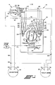
- the control system of the present invention indicated generally at 10 includes a programmer/timer indicated generally at 12, a mode selector switch indicated generally at 14 and an electrical appliance load illustrated as the magnetron 16.
- the programmer/timer 12 includes a rotating cam drum 20 driven by a timer motor 22, connected by dashed line in Fig. 1 and a plurality of cam followers 24, 26 and 28. The cam followers actuate respectively, two groups of switch contacts indicated generally at 30, 32.
- An arming, or line switch operates in conjunction with a group of electrical contacts indicated generally at 34 which are actuated by cam follower 36, which is driven by a separate cam drum 38 operated by an advancing pawl 41 which is oscillated by an eccentric cam driven by the timing motor 22 and contacts a toothed ratchet wheel 39 for advancing the cam 38 in a step-by-step manner.
- the selector switch 14 has a common terminal 40 which is connected through a lead to junction 42, which is connected through a lead to one terminal 44 of the magnetron 16.
- the remaining terminal 46 of the magnetron is connected through a lead to junction 48, which is connected through a lead 50 to one side of a power supply line.
- Switch 14 has a plurality, and preferably five, switching terminals which may be selectably connected to terminal 40 by positioning a switch arm 52 in the desired position to make with any one of the five chosen terminals 54-62.
- the selector switch is shown in the position connecting to terminal 58 in Figure 1 for "MED" power level setting.
- Switch terminals 56 through 62 are each respectively connected to one of the arms of the switch stacks 30, 32; and, terminal 54 is connected through junctions 64 and 66 to one arm of each of the switch stacks 30, 32.
- a lead from junction 66 to junction 68 connects to one terminal 70 of the timing motor 22.
- the remaining terminal 72 of the timing motor is connected via a lead to junction 48 and through lead 50 to one side of the power line.
- Junction 68 is also connected through switch 34 and through lead 74 to the opposite side of the power supply line.
- switch stack 32 One arm of switch stack 32 is connected via lead 76 to an energy absorbing resistor 78 which has the opposite side thereof connected via a lead to junction 42. It will be apparent from Figure 1, that the energy absorbing shunt resistor 78 is connected in parallel, via switch stack 32, with the power selector switch 14 and in series with the magnetron 16.
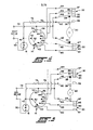
- the terminal 62 of the selector switch 14 represents the "LO" or minimum duty-cycle setting of switch 14 and is connected via a lead to switch contact arm 80 which has a contact 81 thereon.
- the selector switch 14 is shown in Figures 2-5 as positioned in the "LO" power level setting with the moveable arm 52 thereof contacting switch terminal 62.
- the selector switch terminal 60 representing the "MED-LO" power level setting is connected via a lead to contact arm 82 which has a pair of contacts 83, 85 mounted respectively on opposite sides of the arm 82.
- the selector switch terminal 58 representing the "MED" power level setting is connected via a lead to the upper contact arm 84 of the stack 32 and has a contact 87 mounted thereon.
- the selector switch terminal 56 representing the "MED-HI” power level setting, is connected via a lead to contact arm 86 in the stack 32 and has contacts 89, 91 mounted respectively on opposite sides thereof.
- the contact terminal 54 of switch 14 which represents full power or 100% duty-cycle operation is connected to one side of the power line and via junctions and lead 74 and to contact arm 88 in stack 32 and to contact arm 90 in stack 30.
- the arm 88 has a pair of contacts 93, 95 mounted respectively on opposite sides thereof.
- the contact arm 90 in stack 30 has a single contact 97 mounted on one side thereof adjacent the contact 85.
- the resistor lead 76 is connected to the contact arm 92 has a single contact 99 mounted on the end thereof for contacting adjacent contact 95 of the contact arm 88 connected to one side of the power line.
- Contact arm 92 is positioned to be contacted by cam follower 26.
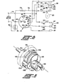
- the rotary cam 20 is operably connected to timer motor 22 by a suitable gear reduction train (not shown) the final drive gear is shown in dashed outline in Figure 9 as having peripheral teeth 94.
- the cam 20 rotates about shaft 96 which is journaled for rotation in the housing 98 (see Fig. 1) in any suitable manner for permitting rotation thereon.
- the cam 20 in the present practice is driven by motor 22 to rotate in a clockwise direction, as viewed in Figure 9.
- Cam 20 is contacted by cam follower 26 on the step-ramp 100 for effecting movement of contact arm 92 and closure of the contact set 95, 99 for applying power to the resistor 78 which condition is shown schematically in Figure 2 wherein the cam 20 is shown in dashed outline; and, the tip of the cam follower 26 is shown in solid black having deflected the arm 92 upwardly.
- Current flows from the power line through lead 74, contact arm 88, closed contact pair 95 and 99, contact arm 92, lead 76, through resistor 78, to magnetron 16 and completes circuit to the opposite side of the power line through lead 50.
- the programmer/timer assumes an operational condition as shown schematically in Figure 4 wherein cam follower 28 is held upwardly lifted to the position shown in the solid black triangle in Figure 4 in which position the contacts 87, 89, 91, 93 are in closed condition by virtue of the upward movement of contact arm 88.
- cam follower 26 has dropped to permit arm 92 for the resistor circuit to open contact set 95, 99 and break the circuit to the resistor 78. This is accomplished by the step-ramp surface 104 on the cam which is opposite surface 102 on the highlift lobe of the cam (see Fig. 9).
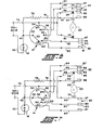
- FIG. 6 schematically represents the condition of the programmer/timer with the cam 20 rotated to a position in which the magnetron 16 is energized during the portion of the duty-cycle after drop-out of resistor 78 and termination of "LO" duty-cycle power level, but before termination of "MED-LOW” power level duty-cycle of the magnetron.
- Fig. 6 schematically represents the condition of the programmer/timer with the cam 20 rotated to a position in which the magnetron 16 is energized during the portion of the duty-cycle after drop-out of resistor 78 and termination of "LO" duty-cycle power level, but before termination of "MED-LOW” power level duty-cycle of the magnetron.
- Figure 7 schematically represents the condition of the programmer/timer with the cam 20 rotated to a position in which the magnetron 16 is energized during the portion of the duty-cycle after drop-out of .resistor 78 and termination of "LO” and "MED-LO” power level duty-cycles but before termination of the "MED" power level duty-cycle of the magnetron.
- the mode selector switch 14 having its wiper arm 52 positioned to make contact with terminal 56 thereof for providing a "MED-HI" duty-cycle operation of the magnetron.
- the programmer/timer 12 is illustrated in Figure 8 as having the cam 20 rotated to a position in which the magnetron 16 is energized during the portion of the duty-cycle after drop-out of resistor 78 and termination of "LO", "MED-LO” and “MED” power level duty-cycles, but before termination of the "MED-HI" power level duty-cycle of the magnetron.
- the mode selector switch 14 is positioned such that contact arm 52 makes contact with terminal 54,. shown in dashed line in Fig. 8, thereby bypassing the contact stacks 32, 30 and permitting power to flow directly from lead 74 through switch terminal 54, contact arm 52 and junction 42 to the magnetron.
- timing diagrams for the programmer/timer switching functions for the resistor 78 and the magnetron plate current for the various selectable power level duty-cycles for the magnetron are based upon the timing motor being geared such that the cam 20 makes one complete revolution in a period of 15 seconds which has been found satisfactory for operation of the programmer/timer in an application for energizing the magnetron of a microwave cooking oven. It will be understood, however, by those skilled in the art that other periods of rotation for the cam may be chosen as required for the particular needs of the appliance to be operated. For simplicity and ease of illustration, the timing diagrams of Figs.
- Figure 10(a) is a plot of current flow I R in the resistor 78 and shows the timing of the energization of the energy absorbing or current limiting resistor 78 wherein contacts 99 and 95 are closed after a .5 second elapsed time from start up of the timing motor to begin current flow through the resistor to the magnetron. They remain closed for approximately 1.5 seconds until an elapsed time of 2.0 seconds, whereupon contacts 95, 99 are broken as shown in the condition schematic. illustrated in Figure 4. It will be understood that the timing of the current limiting resistor 78 remains fixed and is not effected by the changes in position of the power level switch although current flow through the resistor terminates after closure of the contact set associated respectively with the selected power level.
- program cam 20 causes cam follower 24 to close the contact stack 30 for build-up of current flow to the magnetron 16 as shown in Figure 10(b).
- current flow through resistor 78 ceases.
- the initially low plate current flow I m in the magnetron increases at a rate dependent upon the impedance of the load and heating of the filament; and, for a microwave cooking oven magnetron I reaches a maximum after about 1.5 seconds or at the elapsed time of 3.0 seconds. It will be understood that although the current flow through the resistor has been shunted, the resistor is mechanically dropped out by opening of the contacts 95, 99 during this current rise at an elapsed time of 2.0 seconds as noted in Figure 10(a).
- the magnetron in the "LO" power level setting remains energized until an elapsed time of approximately 6 seconds whereupon cam follower 24 breaks the contact between contacts 83, 81, as shown in Figure 5, and terminates current flow to the magnetron.
- the "LO" power level duty-cycle is chosen so as to give the magnetron approximately a 20% duty-cycle energization time for the complete rotational period of the cam.
- the "MED-LO" power level duty-cycle is approximately 40% of the cam rotation period and is terminated in the present practice upon an elapsed time of 9 seconds.
- the "MED-LO" duty-cycle is terminated by cam 20 causing cam follower 24 to move contact arm 90 to break the circuit between contacts 97, 85 as described hereinabove.
- the timing of the magnetron energization for a "MED" power level setting is shown wherein the magnetron plate current I m build up begins at an elapsed time of 1.0 seconds reaches a maximum, and is terminated after an elapsed time of 11.5 seconds.
- the "MED" power level duty-cycle is accomplished by cam follower 28 closing contact 87, 89 as shown in Figure 7, to by-pass resistor 78 and complete the circuit to the magnetron through contact arms 84, 88 and selector switch terminal 58.
- a "MED" power level duty-cycle comprises in the presently preferred practice, approximatly 60% of the period of rotation of the cam 20; and, is terminated by breaking the circuit between contacts 87, 89.
- FIG. 10(e) a timing diagram is shown for the operation of the appliance in the "MED-HI"-power level setting for the selector switch 14.
- the magnetron is energized as shown in Figure l0(e) by closing contacts 91, 93 at an elapsed time of 1.0 seconds to by-pass resistor 78 and build-up magnetron plate current flow through selector switch terminal 56.
- the plate current in the magnetron builds up to a maximum after a total elapsed time of 2.5 seconds; and, the circuit remains closed until a total elapsed time of 14.5 seconds, whereupon the circuit is broken between the contacts 91, 93 to terminate the "MED HI" duty-cycle.
- resistor current I R is plotted in solid black line for the power level selector positioning associated with Figures 10(d) and 10(e) and shown in dashed line for the power level selector positions associated with Figures 10(b) and 10 (c).
- the present invention thus provides a unique and novel way of providing a plurality of power level settings for fractional duty cycling an appliance such as the magnetron in a microwave cooking oven employing a single timer motor driven programmer.
- the invention further provides for transient in-rush current protection by timed shunting of a current limiting resistor during the initial closing of the power switch to the magnetron.
- the present invention prevents overheating of the shunting resistor by the timed dropout of the resistor a short time after the build-up of load current.
Landscapes
- Physics & Mathematics (AREA)
- Electromagnetism (AREA)
- General Physics & Mathematics (AREA)
- Engineering & Computer Science (AREA)
- Automation & Control Theory (AREA)
- Control Of High-Frequency Heating Circuits (AREA)
- Emergency Protection Circuit Devices (AREA)
- Direct Current Feeding And Distribution (AREA)
Applications Claiming Priority (2)
| Application Number | Priority Date | Filing Date | Title |
|---|---|---|---|
| US60917184A | 1984-05-11 | 1984-05-11 | |
| US609171 | 1996-03-01 |
Publications (1)
| Publication Number | Publication Date |
|---|---|
| EP0165351A1 true EP0165351A1 (fr) | 1985-12-27 |
Family
ID=24439636
Family Applications (1)
| Application Number | Title | Priority Date | Filing Date |
|---|---|---|---|
| EP84305041A Withdrawn EP0165351A1 (fr) | 1984-05-11 | 1984-07-25 | Contrôle à multiple-cycles avec limitation du courant de démarrage |
Country Status (5)
| Country | Link |
|---|---|
| EP (1) | EP0165351A1 (fr) |
| JP (1) | JPS60249220A (fr) |
| KR (1) | KR850008723A (fr) |
| AU (1) | AU3123184A (fr) |
| BR (1) | BR8404227A (fr) |
Cited By (3)
| Publication number | Priority date | Publication date | Assignee | Title |
|---|---|---|---|---|
| GB2306260A (en) * | 1995-10-13 | 1997-04-30 | De Longhi Spa | Limiting mains voltage fluctuations caused by overcurrents when an appliance is turned on; microwave ovens |
| ES2116225A1 (es) * | 1996-05-31 | 1998-07-01 | Nakagawa Espana S A | Temporizador para electrodomesticos con sistrema de proteccion contra picos de intensidad integrado. |
| EP1565039A3 (fr) * | 2004-01-20 | 2007-01-03 | Samsung Electronics Co., Ltd. | Four à micro-ondes |
Citations (4)
| Publication number | Priority date | Publication date | Assignee | Title |
|---|---|---|---|---|
| US2838646A (en) * | 1957-11-12 | 1958-06-10 | Gen Electric | Infinitely variable control switch |
| FR1278191A (fr) * | 1959-09-23 | 1961-12-08 | Perfectionnements apportés aux installations de chauffage central | |
| US3842233A (en) * | 1973-05-31 | 1974-10-15 | Tappan Co | Microwave oven defrost circuit |
| DE2941339A1 (de) * | 1979-10-12 | 1981-04-23 | Licentia Patent-Verwaltungs-Gmbh, 6000 Frankfurt | Schaltungsanordnung zur einschaltstrombegrenzung mit einem an einer netzspannungsquelle betriebenen magnetron fuer mikrowellenherde |
Family Cites Families (1)
| Publication number | Priority date | Publication date | Assignee | Title |
|---|---|---|---|---|
| JPS5720125A (en) * | 1980-07-09 | 1982-02-02 | Matsushita Electric Industrial Co Ltd | Rush current diminishing circuit |
-
1984
- 1984-07-11 KR KR1019840004021A patent/KR850008723A/ko not_active Ceased
- 1984-07-25 EP EP84305041A patent/EP0165351A1/fr not_active Withdrawn
- 1984-07-27 AU AU31231/84A patent/AU3123184A/en not_active Abandoned
- 1984-07-30 JP JP59157792A patent/JPS60249220A/ja active Pending
- 1984-08-24 BR BR8404227A patent/BR8404227A/pt unknown
Patent Citations (4)
| Publication number | Priority date | Publication date | Assignee | Title |
|---|---|---|---|---|
| US2838646A (en) * | 1957-11-12 | 1958-06-10 | Gen Electric | Infinitely variable control switch |
| FR1278191A (fr) * | 1959-09-23 | 1961-12-08 | Perfectionnements apportés aux installations de chauffage central | |
| US3842233A (en) * | 1973-05-31 | 1974-10-15 | Tappan Co | Microwave oven defrost circuit |
| DE2941339A1 (de) * | 1979-10-12 | 1981-04-23 | Licentia Patent-Verwaltungs-Gmbh, 6000 Frankfurt | Schaltungsanordnung zur einschaltstrombegrenzung mit einem an einer netzspannungsquelle betriebenen magnetron fuer mikrowellenherde |
Cited By (3)
| Publication number | Priority date | Publication date | Assignee | Title |
|---|---|---|---|---|
| GB2306260A (en) * | 1995-10-13 | 1997-04-30 | De Longhi Spa | Limiting mains voltage fluctuations caused by overcurrents when an appliance is turned on; microwave ovens |
| ES2116225A1 (es) * | 1996-05-31 | 1998-07-01 | Nakagawa Espana S A | Temporizador para electrodomesticos con sistrema de proteccion contra picos de intensidad integrado. |
| EP1565039A3 (fr) * | 2004-01-20 | 2007-01-03 | Samsung Electronics Co., Ltd. | Four à micro-ondes |
Also Published As
| Publication number | Publication date |
|---|---|
| BR8404227A (pt) | 1986-03-11 |
| JPS60249220A (ja) | 1985-12-09 |
| AU3123184A (en) | 1985-11-14 |
| KR850008723A (ko) | 1985-12-21 |
Similar Documents
| Publication | Publication Date | Title |
|---|---|---|
| JP2654464B2 (ja) | 直流電動機制御装置 | |
| JPS6327951B2 (fr) | ||
| EP1340238B1 (fr) | Dispositif de commutation electrique hybride | |
| EP0165351A1 (fr) | Contrôle à multiple-cycles avec limitation du courant de démarrage | |
| EP0637401A1 (fr) | Circuit de commutation a deux relais pour dispositif de commande d'eclairage fluorescent. | |
| CA1220839A (fr) | Commande et programmateur pour appareil menager | |
| EP0373777B1 (fr) | Commande électronique de démarreur | |
| US5828019A (en) | Motorized sequencing switch assembly | |
| EP0128634B1 (fr) | Système de contrôle pour un dispositif électrique | |
| JP3799017B2 (ja) | 3相モータ始動手順の改良式制御方法 | |
| JPH0549294A (ja) | モータの可逆運転装置 | |
| CA1083216A (fr) | Systeme de commande pour moteur electrique compound a courant continu | |
| US4158158A (en) | D.C. controller for battery powered electric motor | |
| US4350944A (en) | Variable control circuit having a timed bypass | |
| JPS5735224A (en) | Control apparatus for heat-cooking appliance | |
| US3361942A (en) | Time switch | |
| JPH0614792B2 (ja) | 可逆回転コンデンサモ−タ | |
| JP3651033B2 (ja) | タップ切換装置の電動制御回路 | |
| CA1064577A (fr) | Dispositif de positionnement pour changeur de prise rotatif commande par moteur | |
| US3273037A (en) | Control circuit | |
| KR0157005B1 (ko) | 전자렌지의 돌입전류 자동 제어 방법 | |
| SU1511859A1 (ru) | Устройство дл управлени асинхронным электродвигателем | |
| KR860001302Y1 (ko) | 유도전동기 정역회전 제어장치 | |
| US5165437A (en) | High accuracy cam-operated fill control | |
| KR0124750Y1 (ko) | 릴레이를 이용한 모터의 역전제동 장치 |
Legal Events
| Date | Code | Title | Description |
|---|---|---|---|
| PUAI | Public reference made under article 153(3) epc to a published international application that has entered the european phase |
Free format text: ORIGINAL CODE: 0009012 |
|
| 17P | Request for examination filed |
Effective date: 19841105 |
|
| AK | Designated contracting states |
Designated state(s): DE FR GB IT |
|
| STAA | Information on the status of an ep patent application or granted ep patent |
Free format text: STATUS: THE APPLICATION IS DEEMED TO BE WITHDRAWN |
|
| 18D | Application deemed to be withdrawn |
Effective date: 19860630 |
|
| RIN1 | Information on inventor provided before grant (corrected) |
Inventor name: WALTASTI, STEPHEN ALBERT Inventor name: LIVERNASH, ROBERT ANTON |