EP0165363A1 - Schaltung zur Erkennung von Stromänderungen - Google Patents
Schaltung zur Erkennung von Stromänderungen Download PDFInfo
- Publication number
- EP0165363A1 EP0165363A1 EP84430019A EP84430019A EP0165363A1 EP 0165363 A1 EP0165363 A1 EP 0165363A1 EP 84430019 A EP84430019 A EP 84430019A EP 84430019 A EP84430019 A EP 84430019A EP 0165363 A1 EP0165363 A1 EP 0165363A1
- Authority
- EP
- European Patent Office
- Prior art keywords
- voltage generator
- current
- circuit
- detection device
- impedance
- Prior art date
- Legal status (The legal status is an assumption and is not a legal conclusion. Google has not performed a legal analysis and makes no representation as to the accuracy of the status listed.)
- Granted
Links
- 238000001514 detection method Methods 0.000 title claims description 16
- 238000001914 filtration Methods 0.000 claims description 2
- 238000004804 winding Methods 0.000 claims 2
- 238000005259 measurement Methods 0.000 abstract 1
- 230000001902 propagating effect Effects 0.000 abstract 1
- 239000003990 capacitor Substances 0.000 description 5
- 239000004020 conductor Substances 0.000 description 2
- 238000009434 installation Methods 0.000 description 2
- 230000003071 parasitic effect Effects 0.000 description 2
- 230000005540 biological transmission Effects 0.000 description 1
- 230000008878 coupling Effects 0.000 description 1
- 238000010168 coupling process Methods 0.000 description 1
- 238000005859 coupling reaction Methods 0.000 description 1
- 238000010586 diagram Methods 0.000 description 1
- 238000002955 isolation Methods 0.000 description 1
- 230000004048 modification Effects 0.000 description 1
- 238000012986 modification Methods 0.000 description 1
- 230000005693 optoelectronics Effects 0.000 description 1
- 238000004904 shortening Methods 0.000 description 1
- 230000003068 static effect Effects 0.000 description 1
Images

Classifications
-
- H—ELECTRICITY
- H04—ELECTRIC COMMUNICATION TECHNIQUE
- H04M—TELEPHONIC COMMUNICATION
- H04M3/00—Automatic or semi-automatic exchanges
- H04M3/22—Arrangements for supervision, monitoring or testing
- H04M3/2272—Subscriber line supervision circuits, e.g. call detection circuits
Definitions
- the present invention relates to a current detector flowing in a circuit which can in particular be a transmission line. It applies more particularly to the detection of the off-hook of a telephone handset by detection of variations in the direct current flowing in the telephone line.
- the present invention provides a device which, while introducing a low series impedance into a circuit, makes it possible to reliably measure variations in current in said circuit.
- the invention relates to a device for detecting variations in the current flowing in a circuit by means of an impedance placed in series in said circuit, a constant voltage generator applied across said impedance and measuring means variations in the current supplied by said constant voltage generator.
- the detector of the invention can be used to detect variations in a current flowing in a telephone line while minimizing the operating conditions of said telephone line.
- FIG. 1 a simplified circuit for locating the invention in the context of a telephone installation.
- the microphone (10) of a subscriber's telephone handset (12) is connected to a CX telephone exchange (14) through an LL telephone line (16).
- the line circuit or interface circuit placed at the outlet of the telephone exchange 14 comprises, in particular, a low frequency transformer (LF) 18 called line transformer, coupling capacitors 20 and a supply circuit 22.
- the speech signals supplied by the microphone 10 are sent to their addressee (not shown) through the transformer BF 18.
- the inductors inductors L1 and L2 create an impedance high alternative preventing the loss of the LF signals from the microphone 10 in the power supply circuit 22.
- the circuit of the invention is shown diagrammatically at 24, making it possible to measure the current IL flowing in the telephone line LL. In fact, what we wish to detect are the variations in this current I L occurring when subscriber 12 picks up his telephone, which causes the switch 26 to close. We have designated by R L , l line impedance.
- any introduction of resistance in series in the line circuit is to the detriment of the maximum possible distance between exchange and subscriber. This explains why it is necessary to reduce as much as possible the series impedance r introduced into the line LL by the measuring device 24.
- a resistance r 10 will be used. ohms. Assuming that the line LL is of a type such that its impedance is 120 ohms / km, the introduction of the line current detector circuit 24 amounts to shortening the radius of the territory that the exchange 14 can serve by 100 m.
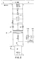
- FIG. 2 shows an embodiment of the detector circuit 24 according to the invention.
- the resistor r which has been chosen to have a value of 10 ohms is shown in the upper part of the figure. It is in series in one of the conductors of the LL line.
- the circuit of the invention will behave as a generator responsible for supplying a predetermined voltage, for example equal to 100 mV, between the terminals of A and-B of the resistor r. That said, the current supplied by said voltage generator will vary as a function of the line current IL proper, passing through r.
- the voltage supplied by the generator is in fact obtained from a 100 kHz high-frequency (HF) wave, for example generated at the primary of an HF 28 transformer, rectified at the secondary of said HF 28 transformer and filtered before being applied. at terminals AB.
- a switching or multivibrator (MV) 30 circuit which connects alternately and at a frequency of 100 kHz, the ends of said primary to ground, is placed across the primary of the HF transformer 28.
- the information sought namely that reflecting the off-hook of the telephone handset (not shown) attached to the LL line, will be available in C as will be seen below.
- a low-pass filter has been placed at C comprising a resistance of 22 k ohms and a capacitor of 4.7 nF responsible for eliminating the parasitic switching noises; and the information sought will be read at point D.
- the secondary of the transformer 28 drives a full-wave rectifier comprising two diodes D1 and D2.
- the middle point of said secondary is connected to point B.
- the output of the rectifier drives a filtering capacitor Cl.
- two diodes D3 and D4 are mounted head-to-tail at the terminals of the capacitor Cl, terminals themselves connected to points A and B respectively.
- the current IL 0.
- the secondary of the transformer 28 will supply 10 mA from the rectified and filtered HF wave, generating a voltage of 100 mV across terminals AB of resistor r.
- a line current IL is supplied by the battery V b (not shown). The current will pass through the resistance r and the expression of the current Is at the secondary of the transformer 28 can be described as follows: with Is always> 0 due to diodes D 1 and D 2 .
- the circuit of the invention uses a DC / DC voltage converter (DC / DC) passing through the generation of an HF wave, which converter delivers a relatively constant DC voltage.
- this voltage is approximately 100 mV.
- the desired isolation between the line and the device for measuring this information is established by the HF transformer 28.
- the HF signal used has a frequency of 100 kHz, any residual component possibly sent over the LL line could not harm the telephone link since it would be outside the so-called telephone frequency band.
- the detection sought can be done regardless of the direction of the current I Z. It will be seen later that the circuit of the invention does better still, it makes it possible to very easily detect a current reversal, for example reflecting an inversion of the poles of the battery V b .
- the PTT admits that a leakage current can exist on the LL line even when the telephone handset attached to it is not lifted.
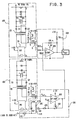
- the circuit of Figure 3 achieves all of the objectives described above through the use of a reference circuit similar to the DC / DC converter of Figure 1.
- a fourth circuit (106) which will be seen below.
- the circuit 106 includes an operational amplifier 108 whose non-inverting input (+) is connected to the output D 'of the reference circuit 102.
- the inverting input (-) of the operational amplifier 108 is connected to a generator (not represented) of alternating voltage whose frequency is included, in the case considered, between 500 and 3000 Hz.
- the output of the generator not shown is connected to one of the terminals of a resistor 110.
- the other terminal of the resistor 110 is connected to a DC voltage source (+ 5 V) through two resistors 114 and 116 and to the (-) terminal of the amplifier 108 through the resistor 114, a capacitor 118 and a resistor 120.
- a resistor 122 establishes a feedback circuit between the output of amplifier 108 and its input (-).
- circuit 106 behaves like an adder circuit.
- This circuit adds an alternating signal called Vref supplied by the generator (not shown) whose frequency is. between 500 and 3000 Hz, at the voltage VrefO obtained at point D 'of the circuit 102.
- Vref alternating signal supplied by the generator (not shown) whose frequency is. between 500 and 3000 Hz
- the circuit elements bearing the references 110 to 122 will be chosen so that the peak-to-peak amplitude of the voltage Vref is such that it corresponds to twice the amplitude of the variation of the voltage which would appear at point D of circuit 100. for a variation of the line current IL of 10 mA.
- the circuit 104 is a comparator circuit of conventional type. It notably includes a voltage comparator 124 whose input (-) is connected to the output of circuit 106 and therefore receives the signal VREF, while its input (+) is connected to point D of circuit 100 and therefore receives voltage DV to analyze.
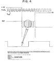
- FIG. 4 shows the different signals to be analyzed.
- the upper line represents the voltages applied to the input of comparator 104.
- the voltage VREF is represented by an alternating wave Vref oscillating around a value VrefO.
- the voltage VD has been represented so as to translate the three different possible cases. Namely, the two extreme cases show a DV of relative amplitude greater than the peak of VREF, but which can be positive (+ VD) or negative (-VD).
- This reflects the fact that the line current IL can flow in a direction from A to B or vice versa from B to A. In fact, the direction of flow of the current IL depends on the polarities of the source V b (see FIG. 1). On the other hand the direction of Is (see figure 2) is invariant. So to translate the off-hook of the subscriber's telephone handset (see Figure 1), the current I S will either increase or decrease.
- the second line of FIG. 4 shows the signal (VOUT) leaving the comparator 124 for input signals according to those represented in the upper part of the figure.
- VOUT the signal leaving the comparator 124 for input signals according to those represented in the upper part of the figure.
- the curve shown remains at one constant logic level translating a so-called combined off-hook state, but furthermore this logical information is either positive or negative.
- This sign translates the polarity of the source V b (see Figure 1).
- This logical information therefore makes it possible either to know this polarity, or to detect a possible permutation of the polarities of V b during operation.
- the central part of the VOUT curve is shown in the lower part of Figure 4 to show how it can be processed by logical means.
- the alternative wave is simply sampled to be analyzed by computer means (not shown) which would indicate whether there is indeed an alternative wave in VOUT translating a subscriber handset on-hook. This avoids false detections of stalls which would be due to parasitic line signals.
Landscapes
- Engineering & Computer Science (AREA)
- Signal Processing (AREA)
- Interface Circuits In Exchanges (AREA)
- Devices For Supply Of Signal Current (AREA)
- Monitoring And Testing Of Exchanges (AREA)
- Control Of Charge By Means Of Generators (AREA)
Priority Applications (9)
| Application Number | Priority Date | Filing Date | Title |
|---|---|---|---|
| EP84430019A EP0165363B1 (de) | 1984-06-20 | 1984-06-20 | Schaltung zur Erkennung von Stromänderungen |
| DE8484430019T DE3473803D1 (en) | 1984-06-20 | 1984-06-20 | Detection circuit for current varations |
| IE335/85A IE56075B1 (en) | 1984-06-20 | 1985-02-12 | Circuit for detecting current variations |
| JP60050731A JPS6113796A (ja) | 1984-06-20 | 1985-03-15 | 回線を流れる電流の変動を検出するための装置 |
| ES542727A ES8607652A1 (es) | 1984-06-20 | 1985-04-30 | Un dispositivo para detectar variaciones de una corriente que circula por un circuito |
| CA000480611A CA1261922A (en) | 1984-06-20 | 1985-05-02 | Circuit for detecting current variations |
| BR8502791A BR8502791A (pt) | 1984-06-20 | 1985-06-12 | Circuito para detectar variacoes de corrente |
| AU43683/85A AU4368385A (en) | 1984-06-20 | 1985-06-14 | Current measurement in telephone circuits |
| US07/030,263 US4731829A (en) | 1984-06-20 | 1987-03-24 | Circuit for detecting current variations |
Applications Claiming Priority (1)
| Application Number | Priority Date | Filing Date | Title |
|---|---|---|---|
| EP84430019A EP0165363B1 (de) | 1984-06-20 | 1984-06-20 | Schaltung zur Erkennung von Stromänderungen |
Publications (2)
| Publication Number | Publication Date |
|---|---|
| EP0165363A1 true EP0165363A1 (de) | 1985-12-27 |
| EP0165363B1 EP0165363B1 (de) | 1988-08-31 |
Family
ID=8192949
Family Applications (1)
| Application Number | Title | Priority Date | Filing Date |
|---|---|---|---|
| EP84430019A Expired EP0165363B1 (de) | 1984-06-20 | 1984-06-20 | Schaltung zur Erkennung von Stromänderungen |
Country Status (9)
| Country | Link |
|---|---|
| US (1) | US4731829A (de) |
| EP (1) | EP0165363B1 (de) |
| JP (1) | JPS6113796A (de) |
| AU (1) | AU4368385A (de) |
| BR (1) | BR8502791A (de) |
| CA (1) | CA1261922A (de) |
| DE (1) | DE3473803D1 (de) |
| ES (1) | ES8607652A1 (de) |
| IE (1) | IE56075B1 (de) |
Cited By (1)
| Publication number | Priority date | Publication date | Assignee | Title |
|---|---|---|---|---|
| KR101251895B1 (ko) * | 2008-08-13 | 2013-04-08 | 알까뗄 루슨트 | 셀룰러 무선 통신 네트워크 및 대응하는 기지국의 다운링크 방향에서 간섭을 줄이기 위한 방법 |
Families Citing this family (7)
| Publication number | Priority date | Publication date | Assignee | Title |
|---|---|---|---|---|
| US5490210A (en) * | 1993-12-07 | 1996-02-06 | Sasso; Bill J. | Programmable telephone interface device |
| SE9400186D0 (sv) * | 1994-01-21 | 1994-01-21 | Ericsson Telefon Ab L M | Förfarande i ett telekommunikationssystem |
| US5544241A (en) * | 1995-06-27 | 1996-08-06 | Andrew S. Dibner | Telephone ring detector |
| KR0173403B1 (ko) * | 1996-04-25 | 1999-04-01 | 김광호 | 전화단말기의 통화로 자동복구 장치 및 그 방법 |
| US5896446A (en) * | 1996-07-29 | 1999-04-20 | Mars Incorporated | Coin operated telephone auditor |
| WO1999053627A1 (en) | 1998-04-10 | 1999-10-21 | Chrimar Systems, Inc. Doing Business As Cms Technologies | System for communicating with electronic equipment on a network |
| US7346785B2 (en) * | 1999-01-12 | 2008-03-18 | Microsemi Corp. - Analog Mixed Signal Group Ltd. | Structure cabling system |
Citations (4)
| Publication number | Priority date | Publication date | Assignee | Title |
|---|---|---|---|---|
| FR2216585A1 (de) * | 1973-02-02 | 1974-08-30 | Cit Alcatel | |
| DE2851848B1 (de) * | 1978-11-30 | 1980-01-24 | Siemens Ag | Schaltungsanordnung zum Ermitteln des Belegungszustands einer Fernsprechleitung |
| FR2439998A1 (fr) * | 1978-10-25 | 1980-05-23 | Erne Hansjoerg | Appareil de controle du courant de ligne dans une ligne telephonique |
| FR2460077A1 (fr) * | 1979-06-26 | 1981-01-16 | Constr Telephoniques | Circuit de detection de courant |
Family Cites Families (8)
| Publication number | Priority date | Publication date | Assignee | Title |
|---|---|---|---|---|
| FR2172537A5 (de) * | 1972-02-17 | 1973-09-28 | Constr Telephoniques | |
| US4127747A (en) * | 1977-09-23 | 1978-11-28 | Northern Telecom Limited | Voltage boost circuit for telephone systems |
| NL7810086A (nl) * | 1978-10-06 | 1980-04-09 | Philips Nv | Voedingsbrug voor een abonneestroomloop. |
| JPS5854773A (ja) * | 1981-09-28 | 1983-03-31 | Nec Corp | 加入者回路 |
| US4454477A (en) * | 1982-04-28 | 1984-06-12 | At&T Bell Laboratories | Loop current detector with threshold setting impedance |
| US4524246A (en) * | 1982-07-07 | 1985-06-18 | Harris Corporation | SLIC II--common-mode current rejection |
| US4429186A (en) * | 1982-09-30 | 1984-01-31 | Gte Automatic Electric Inc. | Floating battery feed circuit for telephone subscriber line interface |
| US4591663A (en) * | 1983-11-17 | 1986-05-27 | Trad, Inc. | Servo-linearized opto-electronic analog interface |
-
1984
- 1984-06-20 EP EP84430019A patent/EP0165363B1/de not_active Expired
- 1984-06-20 DE DE8484430019T patent/DE3473803D1/de not_active Expired
-
1985
- 1985-02-12 IE IE335/85A patent/IE56075B1/en not_active IP Right Cessation
- 1985-03-15 JP JP60050731A patent/JPS6113796A/ja active Granted
- 1985-04-30 ES ES542727A patent/ES8607652A1/es not_active Expired
- 1985-05-02 CA CA000480611A patent/CA1261922A/en not_active Expired
- 1985-06-12 BR BR8502791A patent/BR8502791A/pt not_active IP Right Cessation
- 1985-06-14 AU AU43683/85A patent/AU4368385A/en not_active Abandoned
-
1987
- 1987-03-24 US US07/030,263 patent/US4731829A/en not_active Expired - Fee Related
Patent Citations (4)
| Publication number | Priority date | Publication date | Assignee | Title |
|---|---|---|---|---|
| FR2216585A1 (de) * | 1973-02-02 | 1974-08-30 | Cit Alcatel | |
| FR2439998A1 (fr) * | 1978-10-25 | 1980-05-23 | Erne Hansjoerg | Appareil de controle du courant de ligne dans une ligne telephonique |
| DE2851848B1 (de) * | 1978-11-30 | 1980-01-24 | Siemens Ag | Schaltungsanordnung zum Ermitteln des Belegungszustands einer Fernsprechleitung |
| FR2460077A1 (fr) * | 1979-06-26 | 1981-01-16 | Constr Telephoniques | Circuit de detection de courant |
Cited By (1)
| Publication number | Priority date | Publication date | Assignee | Title |
|---|---|---|---|---|
| KR101251895B1 (ko) * | 2008-08-13 | 2013-04-08 | 알까뗄 루슨트 | 셀룰러 무선 통신 네트워크 및 대응하는 기지국의 다운링크 방향에서 간섭을 줄이기 위한 방법 |
Also Published As
| Publication number | Publication date |
|---|---|
| JPS6113796A (ja) | 1986-01-22 |
| ES542727A0 (es) | 1986-05-16 |
| JPH0533600B2 (de) | 1993-05-19 |
| ES8607652A1 (es) | 1986-05-16 |
| IE850335L (en) | 1985-12-20 |
| CA1261922A (en) | 1989-09-26 |
| BR8502791A (pt) | 1986-02-18 |
| AU4368385A (en) | 1986-01-02 |
| EP0165363B1 (de) | 1988-08-31 |
| US4731829A (en) | 1988-03-15 |
| IE56075B1 (en) | 1991-04-10 |
| DE3473803D1 (en) | 1988-10-06 |
Similar Documents
| Publication | Publication Date | Title |
|---|---|---|
| EP1221783B1 (de) | Fernspeisungsvorrichtung für ein Endgerät in einem Telekommunikations Netzwerk, Konzentrator und Wiederholungsanordnung mit einer solchen Vorrichtung | |
| EP1100226B1 (de) | Verfahren zur Fernspeisung eines Endgerätes in einem lokalen Netz | |
| FR2677831A1 (fr) | Modem a circuit d'interface de ligne perfectionne, notamment pour ordinateur. | |
| FR2760163A1 (fr) | Appareil de telecommunication muni d'un dispositif de reconnaissance de peripheriques | |
| FR2471708A1 (fr) | Circuit d'alimentation en courant comportant une fonction de detection de court-circuit a la terre pour systeme de telecommunication | |
| CH624517A5 (en) | Electronic hybrid circuit | |
| EP0022561A1 (de) | Vorrichtung zum Speisen einer Teilnehmerstation | |
| EP0165363B1 (de) | Schaltung zur Erkennung von Stromänderungen | |
| EP0004815B1 (de) | Verfahren zum Übertragen elektrischer Signale mittels optischer Verbindung und Vorrichtung zur automatischen Verstärkungsregelung eines an der optischen Verbindung gekuppelten Empfangsweges | |
| FR2810819A1 (fr) | Procede et appareil pour connecter des signaux vocaux et de donnees large bande sur des systemes telephoniques | |
| FR2652697A1 (fr) | Extracteur de donnees numeriques dans un signal video. | |
| FR2695286A1 (fr) | Système de détection et de signalisation de lampes défaillantes dans un réseau d'éclairage. | |
| FR2500699A1 (fr) | Circuit d'economie d'energie, notamment pour circuit de ligne d'abonne telephonique | |
| EP0404002B1 (de) | Detektor für Niederfrequenz-Wechselstromsignale für eine Telefonverbindungsleitung | |
| EP2415179B1 (de) | System und vorrichtung zur kommunikation über stromversorgungsleitungen | |
| EP0796434A1 (de) | Anordnung zum lokalisieren von fehlern bei unterwasserkommunikationskabeln | |
| EP0055650B1 (de) | Schaltung zur Verbindung eines aktiven Mikrophons, insbesondere mit Elektret, mit einer Fernsprechübertragungsschaltung | |
| FR2460576A1 (fr) | Circuit d'alimentation a trois bornes pour appareil telephonique | |
| EP0966800B1 (de) | Steuervorrichtung für trägerstromübertragung auf einem niedervoltnetz | |
| FR2859856A1 (fr) | Systeme et disposiif d'alimentation a distance d'un equipement de traitement d'informations | |
| FR2800955A1 (fr) | Procede de telealimentation d'un terminal dans un reseau local, dispositif de telealimentation et terminal correspondants | |
| EP1480434B1 (de) | Verfahren und Vorrichtung zur Energieübertragung in einem drahtgebundenen Telekommunikationssystem | |
| FR2999831A1 (fr) | Dispositif de demodulation | |
| FR2581279A1 (fr) | Circuit telephonique, integrable monolithiquement, pour l'alimentation d'une ligne telephonique d'abonne | |
| EP0165640A1 (de) | Vorrichtung zur galvanischen Isolierung zwischen einem Impulsgeber und einer Belastung |
Legal Events
| Date | Code | Title | Description |
|---|---|---|---|
| PUAI | Public reference made under article 153(3) epc to a published international application that has entered the european phase |
Free format text: ORIGINAL CODE: 0009012 |
|
| AK | Designated contracting states |
Designated state(s): BE DE FR GB IT NL |
|
| 17P | Request for examination filed |
Effective date: 19860424 |
|
| 17Q | First examination report despatched |
Effective date: 19870520 |
|
| GRAA | (expected) grant |
Free format text: ORIGINAL CODE: 0009210 |
|
| AK | Designated contracting states |
Kind code of ref document: B1 Designated state(s): BE DE FR GB IT NL |
|
| GBT | Gb: translation of ep patent filed (gb section 77(6)(a)/1977) | ||
| REF | Corresponds to: |
Ref document number: 3473803 Country of ref document: DE Date of ref document: 19881006 |
|
| ITF | It: translation for a ep patent filed | ||
| PLBE | No opposition filed within time limit |
Free format text: ORIGINAL CODE: 0009261 |
|
| STAA | Information on the status of an ep patent application or granted ep patent |
Free format text: STATUS: NO OPPOSITION FILED WITHIN TIME LIMIT |
|
| PG25 | Lapsed in a contracting state [announced via postgrant information from national office to epo] |
Ref country code: BE Effective date: 19890630 |
|
| 26N | No opposition filed | ||
| BERE | Be: lapsed |
Owner name: INTERNATIONAL BUSINESS MACHINES CORP. Effective date: 19890630 |
|
| ITTA | It: last paid annual fee | ||
| PGFP | Annual fee paid to national office [announced via postgrant information from national office to epo] |
Ref country code: NL Payment date: 19920630 Year of fee payment: 9 |
|
| PG25 | Lapsed in a contracting state [announced via postgrant information from national office to epo] |
Ref country code: NL Effective date: 19940101 |
|
| NLV4 | Nl: lapsed or anulled due to non-payment of the annual fee | ||
| PGFP | Annual fee paid to national office [announced via postgrant information from national office to epo] |
Ref country code: GB Payment date: 19940511 Year of fee payment: 11 |
|
| PGFP | Annual fee paid to national office [announced via postgrant information from national office to epo] |
Ref country code: FR Payment date: 19940531 Year of fee payment: 11 |
|
| PGFP | Annual fee paid to national office [announced via postgrant information from national office to epo] |
Ref country code: DE Payment date: 19940629 Year of fee payment: 11 |
|
| PG25 | Lapsed in a contracting state [announced via postgrant information from national office to epo] |
Ref country code: GB Effective date: 19950620 |
|
| GBPC | Gb: european patent ceased through non-payment of renewal fee |
Effective date: 19950620 |
|
| PG25 | Lapsed in a contracting state [announced via postgrant information from national office to epo] |
Ref country code: FR Effective date: 19960229 |
|
| PG25 | Lapsed in a contracting state [announced via postgrant information from national office to epo] |
Ref country code: DE Effective date: 19960301 |
|
| REG | Reference to a national code |
Ref country code: FR Ref legal event code: ST |