EP0165370B1 - Hängevorrichtung - Google Patents
Hängevorrichtung Download PDFInfo
- Publication number
- EP0165370B1 EP0165370B1 EP84870198A EP84870198A EP0165370B1 EP 0165370 B1 EP0165370 B1 EP 0165370B1 EP 84870198 A EP84870198 A EP 84870198A EP 84870198 A EP84870198 A EP 84870198A EP 0165370 B1 EP0165370 B1 EP 0165370B1
- Authority
- EP
- European Patent Office
- Prior art keywords
- tubular element
- guide
- threaded rod
- guide member
- band
- Prior art date
- Legal status (The legal status is an assumption and is not a legal conclusion. Google has not performed a legal analysis and makes no representation as to the accuracy of the status listed.)
- Expired
Links
- 239000000725 suspension Substances 0.000 title claims abstract description 32
- 229910000831 Steel Inorganic materials 0.000 claims description 4
- 239000010959 steel Substances 0.000 claims description 4
- 239000000463 material Substances 0.000 claims description 3
- 229920002994 synthetic fiber Polymers 0.000 claims 2
- 229910001335 Galvanized steel Inorganic materials 0.000 claims 1
- 239000008397 galvanized steel Substances 0.000 claims 1
- 239000002184 metal Substances 0.000 claims 1
- XLYOFNOQVPJJNP-UHFFFAOYSA-N water Substances O XLYOFNOQVPJJNP-UHFFFAOYSA-N 0.000 description 3
- 238000010438 heat treatment Methods 0.000 description 2
- 238000009434 installation Methods 0.000 description 2
- 230000035939 shock Effects 0.000 description 2
- 238000004378 air conditioning Methods 0.000 description 1
- 230000000712 assembly Effects 0.000 description 1
- 238000000429 assembly Methods 0.000 description 1
- 238000010276 construction Methods 0.000 description 1
- 239000012530 fluid Substances 0.000 description 1
- -1 heating pipes Substances 0.000 description 1
- 238000004519 manufacturing process Methods 0.000 description 1
Images

Classifications
-
- F—MECHANICAL ENGINEERING; LIGHTING; HEATING; WEAPONS; BLASTING
- F16—ENGINEERING ELEMENTS AND UNITS; GENERAL MEASURES FOR PRODUCING AND MAINTAINING EFFECTIVE FUNCTIONING OF MACHINES OR INSTALLATIONS; THERMAL INSULATION IN GENERAL
- F16L—PIPES; JOINTS OR FITTINGS FOR PIPES; SUPPORTS FOR PIPES, CABLES OR PROTECTIVE TUBING; MEANS FOR THERMAL INSULATION IN GENERAL
- F16L3/00—Supports for pipes, cables or protective tubing, e.g. hangers, holders, clamps, cleats, clips, brackets
- F16L3/22—Supports for pipes, cables or protective tubing, e.g. hangers, holders, clamps, cleats, clips, brackets specially adapted for supporting a number of parallel pipes at intervals
-
- F—MECHANICAL ENGINEERING; LIGHTING; HEATING; WEAPONS; BLASTING
- F16—ENGINEERING ELEMENTS AND UNITS; GENERAL MEASURES FOR PRODUCING AND MAINTAINING EFFECTIVE FUNCTIONING OF MACHINES OR INSTALLATIONS; THERMAL INSULATION IN GENERAL
- F16L—PIPES; JOINTS OR FITTINGS FOR PIPES; SUPPORTS FOR PIPES, CABLES OR PROTECTIVE TUBING; MEANS FOR THERMAL INSULATION IN GENERAL
- F16L3/00—Supports for pipes, cables or protective tubing, e.g. hangers, holders, clamps, cleats, clips, brackets
- F16L3/14—Hangers in the form of bands or chains
Definitions
- the present invention relates to a new suspension device, more particularly intended for pipes with circulation of fluids, such as heating pipes, water pipes, discharges, air conditioning ... etc.
- Documents DE-A-3 204 023 and US-A-1 642 131 disclose a suspension device or the like comprising a fixing bracket in the form of a strip and open towards the end, the two folded free ends of which are fixed to a rod threaded by a nut provided with a recess in which the ends of the stirrup engage, a safety sleeve covering the ends of the stirrup engaged in the nut so as to lock the assembly.
- Document BE-A-897 512 discloses a suspension device similar to the preceding ones, in which the collar which generally follows the shape of the pipe to be suspended is assembled with the nut by means of lugs which engage in adequate holes in the collar. These devices only make it difficult to adjust the height of the pipe once it is suspended. On the other hand, these devices do not allow the pipe to be rigidly suspended or to adjust the tightness of the pipe in its bracket.
- the object of the present invention is to provide a new pipe suspension device, of a simpler design, and therefore being less expensive.
- the invention aims to provide a suspension device which makes it possible to fix the pipes in a stable manner or with a certain mobility, either to take up the stresses due to pressure waves, or to allow a sliding of the pipes due to the thermal expansion.
- Another object of the present invention aims to provide a suspension device which simplifies the manipulations of the operator, during the mounting of said device.
- a suspension device comprising a tubular element one end of which is open and the opposite end of which has a passage opening for a substantially concentric threaded rod which carries, at one end, a guide associated with a nut and engaged in the two ends of a thin strip so as to form a collar characterized in that said tubular element is provided with at least one substantially longitudinal guide slot in which slides said guide element provided with '' at least one corresponding guide tab and in that said suspension device comprises a second nut mounted on said threaded rod, outside the tubular element on the side having the opening for passage of said threaded rod, allowing during of its tightening against said tubular element, to slide, in the longitudinal slot thereof, said guide element which drives the strip inside said tubular element by the open end of the latter to tension it and / or tighten it around the pipe to be suspended or the like to be suspended.
- the tubular element comprises two parallel and opposite guide slots.
- the nut is advantageously secured to the sliding guide element in said two opposite guide slots by means of two tabs guide, each of which is adapted to the corresponding guide slot.
- the two free ends of the band which forms the collar are engaged on two opposite sides of said guide element, preferably those which include the guide tabs.
- the two free ends of the strip which forms the collar are engaged on the same guide tab of the guide element.
- the two free ends of a first band which forms a first collar are engaged on a first side of said guide element and the two free ends of a second band which forms a second collar are engaged on a second side of said guide member preferably a side opposite the first side.
- the threaded rod is fixed in a manner known per se to the ceiling or to a vertical wall.
- the threaded rod is mounted in an angularly mobile manner on a stirrup generally affecting the shape of a U, the uprights of which are provided with legs turned towards the outside, said stirrup being able to slide in a U-shaped rail. overturned, the uprights of which are provided with legs turned inwards, the said stirrup being wedged in the said rail by a screw which makes it possible to separate the uprights from the stirrup and to wedge them against the inner lugs of the rail.
- the stirrup uprights have opposite notches on the stirrup uprights, which allow the stirrup to be inserted into the rail by simple rotation of said stirrup around its central axis.
- the device of the present invention is simple from the point of view of its manufacture as well as from the point of view of its assembly.
- the assembly operations of the device are very simple: first, the operator mounts the threaded rod to the ceiling and slides the tubular element thereon to abut against said second nut; then, it slightly bends a thin strip around the pipe to be suspended and joins the two ends of the latter by said guide element associated with a first nut into which it has introduced the threaded rod; it folds down the tubular element so as to introduce the guide tabs of said guide element into the guide slots and it tightens said second nut against the tubular element.
- the suspension device according to the invention can be adapted to several dimensions of the pipes to be suspended and that it suffices, to do this, to choose a sufficiently long tubular element which makes it possible to receive the ends of the strip turned around of the pipe.
- the operator does not need to take care of the various devices adapted to the various dimensions of pipes, but it suffices that he takes with him a dimension of the suspension device according to the invention suitable for several dimensions of pipes, most common examples.
- the operator does not have to assemble many parts on site, which facilitates his work, in particular when the user is on a ladder or scaffolding for example, and reduces the working time.
- the suspension device comprises a tubular element 1 of square section, one end of which is open and the opposite end of which is closed by a plug 7.
- said plug 7 may advantageously consist of a plastic plug adapted to the end of the tubular element and traversed by an opening adapted to the diameter of the threaded rod, the opening being advantageously provided with a lip 11 which allows a certain attachment of the tubular element to the threaded rod during assembly of the suspension device according to the present invention.
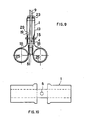
- the tubular element 1 can be made from a sheet cut out in the shape of FIG. 10 and folded along the broken lines so as to obtain a tubular element. 1 open at one end and having, at the opposite end, a passage opening 6 for the threaded rod.
- Said tubular element 1 is also provided with two substantially opposite longitudinal guide slots 13 in which slides a guide element 15 associated with a first nut, which is provided with two corresponding guide tabs 17.
- the guide element 15 and said first nut form a single piece, as shown in Figures 5 to 7. It may nevertheless be advantageous to use a nut separate from the guide element, when for reasons of space, it is to suspend a pipe to the ceiling for example (see below).
- FIGS. 5 to 7 various forms of guide tabs 17 are shown, which are not, however, limiting; it is also possible to combine two tabs 17 of different types on the same guide element or to provide hook-shaped guide tabs, said hook leaving the plane of the drawing (Fig. 5).
- the guide tabs 17 of the element 15 are engaged in the two ends (19, 20) of the thin strip which forms a collar around the pipe to be hung (FIGS. 2 to 4).
- the two ends (19 and 20) of the strip advantageously have rectangular, round, T-shaped or cross-shaped cutouts (21 and 22) which are adapted to the tabs 17 of the guide element 15. It is also possible combine different cuts on the same strip 18.
- the strip 18 can advantageously be perforated at regular distance from T-shaped holes each time opposite or in the form of a cross 18 '. Thus, the operator can cut an adequate length of strip out of a strip produced in great length.
- a steel strip 18 having a thickness of between 0.5 and 1.5 mm is used.
- other strips can also be used, in particular plastic strips or steel strips covered with a plastic material or a rubber.
- the guide element 15 is advantageously mounted, by means of said first nut, on the end of the threaded rod so that the tightening of a second nut 23 causes the two nuts to come together by tightening the strip 18 around of pipe 25 to hang. The guide element 15 thus slides in the guide slots 13.
- the ends of the strip 18 are each hung in one of the opposite tabs of the guide element.
- the two ends of the strip 18 are hooked in the same guide tab 17 of the guide element 15.
- the tubular element 1 has, on the open side, two opposite holes 4 whose centers are on an axis substantially perpendicular to the plane which contains the axes of symmetry of the two guide slots 13.
- a significant tightening of the strip 18 around the pipe 25 can cause a deformation thereof, inside the tubular element, which prevents a free rotary movement of the threaded rod 9. It is therefore possible, for example, to place a screwdriver in these holes 4 which allows adequate flow of the strip 18.
- the different steps for mounting the suspension device are as follows: first, the threaded rod 9 is fixed to the ceiling or to the wall; there is then introduced the nut 23 and then the tubular guide element 1 which will hang on the threaded rod 9 thanks to the lips 11 of the plug 7; the nut 15 is introduced on the threaded rod; the band (s) 18 is folded around the pipe (s) to be suspended and the ends 19 and 20 of the latter are hooked in the guide tabs 17 of said nut 15 and the flap l 'tubular element 1 so that the guide tabs 17 enter the guide slots 13 thereof and, then, the nut 23 is tightened so as to bring it closer to the nut 15.
- the strip 18 “flows into the tubular guide element but the nut 15 does not deviate from the ceiling. It can also be seen that, depending on the chosen length of the tubular guide element 1, the same strip 18 can be used for different dimensions of tubes to be hung 25. To do this, it suffices to introduce the nut 15 more or less far from the threaded rod 9.
- a housing having a length of 55 mm and a strip of corresponding length, it is possible to suspend pipes having a diameter of 15 mm, 22 mm, 28 mm, 35 mm and 42 mm.
- the device according to the present invention is particularly easy to handle and is suitable for many assemblies in places which are difficult to access.
- the device when the guide element 15 is not secured to the first nut, the device is well suited for mounting tubes or the like very close to the ceiling.
- the tube can then be lifted so that its weight no longer presses on said first nut via the guide element 15 and that, when the threaded rod is fixed to the ceiling, the rotation thereof 'does not cause said first nut to rotate; therefore, the initial setting is maintained.
- a significant advantage of the present invention consists in that, even in this case, the suspended tube is centered relative to the threaded rod 9, when tightening the second nut, since the tightening force is central.
- guide element 1 can adapt to different diameters of threaded rods.
- direct fixing to the ceiling or wall can be provided, as well as indirect fixing by means of the device described below and shown in FIGS. 11 and 12.
- a stable or mobile assembly can be achieved by tightening the strip 18 more or less tightly around the pipe 25. Nevertheless, the mobility of the suspension can be further improved by the choice of an adequate fixing of the rod. threaded in the ceiling or in the wall, such as for example the device described below and shown in Figure 11 where the threaded rod 9 is suspended in a pendulum fashion.
- the fixing device consists of a stirrup 31 generally affecting the shape of a U whose uprights are provided with lugs 33 facing outwards, said stirrup 31 being able to slide in a rail in U overturned 35 whose uprights are provided with legs 37 facing inwards.
- the stirrup can advantageously be wedged in said rail by a screw 39 which spreads the uprights of the stirrup 31 and wedges them against the inner lugs 37 of the rail 35.
- the stirrup has opposite notches 41 arranged on the uprights of the latter and located directly below the legs 33 facing outwards.
Landscapes
- Engineering & Computer Science (AREA)
- General Engineering & Computer Science (AREA)
- Mechanical Engineering (AREA)
- Supports For Pipes And Cables (AREA)
- Clamps And Clips (AREA)
- Load-Engaging Elements For Cranes (AREA)
- Electrical Discharge Machining, Electrochemical Machining, And Combined Machining (AREA)
- Vehicle Body Suspensions (AREA)
Claims (14)
Priority Applications (1)
| Application Number | Priority Date | Filing Date | Title |
|---|---|---|---|
| AT84870198T ATE34030T1 (de) | 1984-05-14 | 1984-12-27 | Haengevorrichtung. |
Applications Claiming Priority (2)
| Application Number | Priority Date | Filing Date | Title |
|---|---|---|---|
| LU85357 | 1984-05-14 | ||
| LU85357A LU85357A1 (fr) | 1984-05-14 | 1984-05-14 | Dispositif de suspension |
Publications (2)
| Publication Number | Publication Date |
|---|---|
| EP0165370A1 EP0165370A1 (de) | 1985-12-27 |
| EP0165370B1 true EP0165370B1 (de) | 1988-05-04 |
Family
ID=19730257
Family Applications (1)
| Application Number | Title | Priority Date | Filing Date |
|---|---|---|---|
| EP84870198A Expired EP0165370B1 (de) | 1984-05-14 | 1984-12-27 | Hängevorrichtung |
Country Status (4)
| Country | Link |
|---|---|
| EP (1) | EP0165370B1 (de) |
| AT (1) | ATE34030T1 (de) |
| DE (2) | DE3470930D1 (de) |
| LU (1) | LU85357A1 (de) |
Families Citing this family (9)
| Publication number | Priority date | Publication date | Assignee | Title |
|---|---|---|---|---|
| EP0274760B1 (de) * | 1987-01-15 | 1991-02-27 | Geberit AG Armaturen & Apparatefabrik | Anlage mit einer freiliegend aufgehängten Rohrleitung |
| ITVR940007A1 (it) * | 1994-02-07 | 1995-08-07 | Emilio Scotti | Collare di supporto per tubazioni |
| RU2272209C1 (ru) * | 2004-05-31 | 2006-03-20 | Общество с ограниченной ответственностью "Производственно-строительная фирма "Возрождение" | Кронштейн для крепления кабеля |
| US7600483B2 (en) * | 2005-08-31 | 2009-10-13 | Radar Engineers, Inc. | Marker for buried objects |
| RU2338947C2 (ru) * | 2006-12-11 | 2008-11-20 | Виктор Федорович Гилин | Кронштейн для крепления кабеля |
| RU2338948C1 (ru) * | 2007-01-09 | 2008-11-20 | Виктор Федорович Гилин | Кронштейн для крепления кабеля на столбах посредством монтажной ленты |
| RU2389115C1 (ru) * | 2009-03-18 | 2010-05-10 | Закрытое Акционерное Общество "Мзва" | Анкерный кронштейн (варианты) |
| RU2391758C1 (ru) * | 2009-04-15 | 2010-06-10 | Закрытое Акционерное Общество "Мзва" | Анкерный кронштейн |
| RU2706255C2 (ru) * | 2017-12-15 | 2019-11-18 | Бочкарев Михаил Александрович | Кабельный зажим |
Family Cites Families (4)
| Publication number | Priority date | Publication date | Assignee | Title |
|---|---|---|---|---|
| US1642131A (en) * | 1927-09-13 | tomkinson | ||
| DE2932936A1 (de) * | 1979-08-14 | 1981-02-26 | Siemens Ag | Abfangschelle fuer schirmlose kabel |
| DE3204023A1 (de) * | 1982-02-05 | 1983-08-18 | Sikla GmbH & Co KG, 7201 Hausen | Rohrabhaengung |
| BE897512A (fr) * | 1983-08-10 | 1983-12-01 | Vrijhof Jan | Dispositif de suspension |
-
1984
- 1984-05-14 LU LU85357A patent/LU85357A1/fr unknown
- 1984-12-27 EP EP84870198A patent/EP0165370B1/de not_active Expired
- 1984-12-27 AT AT84870198T patent/ATE34030T1/de not_active IP Right Cessation
- 1984-12-27 DE DE8484870198T patent/DE3470930D1/de not_active Expired
-
1985
- 1985-01-12 DE DE8500671U patent/DE8500671U1/de not_active Expired
Also Published As
| Publication number | Publication date |
|---|---|
| LU85357A1 (fr) | 1986-01-29 |
| DE3470930D1 (en) | 1988-06-09 |
| EP0165370A1 (de) | 1985-12-27 |
| DE8500671U1 (de) | 1985-05-30 |
| ATE34030T1 (de) | 1988-05-15 |
Similar Documents
| Publication | Publication Date | Title |
|---|---|---|
| EP0479719B1 (de) | Aufrolleinrichtung mit rohrförmigem Motor für Stores, Jalousien oder dergleichen | |
| EP0816202A1 (de) | Anordnung eines Werkzeugträgers auf einer Schubkarre | |
| FR2717246A1 (fr) | Attache de repli du type en ciseaux. | |
| EP0165370A1 (de) | Hängevorrichtung | |
| FR2517240A1 (fr) | Dispositif de fixation de ratelier a outils | |
| FR2757344A1 (fr) | Debroussailleuse | |
| FR2518192A1 (fr) | Dispositif d'assemblage de deux pieces, telles que deux profiles realises par exemple en alliage leger | |
| CA2085085A1 (fr) | Dispositif de jonction invisible, notamment pour toiles tendues | |
| EP3354910A1 (de) | Klammer, insbesondere zur halterung von gegenständen, wie etwa rohrleitungen oder kabeln, auf einer halterungsstruktur mithilfe eines gewindeorgans | |
| EP3400858B1 (de) | Befestigungsvorrichtung von heizkörperzubehörteilen | |
| EP3115623B1 (de) | Vorrichtung zum zusammenbau und zur verriegelung | |
| CH648631A5 (en) | Fixing device for scaffolding | |
| FR2517411A1 (fr) | Embase autoverrouillante pour la fixation d'un objet sur un profile | |
| FR2626606A1 (fr) | Bride de fixation d'un coffrage tubulaire | |
| BE897512A (fr) | Dispositif de suspension | |
| CH659309A5 (en) | Device for fitting pipes, especially water drainage pipes | |
| FR2769934A1 (fr) | Support pour gouttiere | |
| FR2544411A1 (fr) | Dispositif de fixation a ecrou retenu en une seule piece | |
| FR2472071A1 (fr) | Dispositif de suspension pour portes ou portails | |
| EP0205722B1 (de) | Befestigungseinrichtung eines Heizkörpers am Boden | |
| FR2796821A3 (fr) | Organe de fixation de rayons, tiroirs ou autres sur un montant vertical | |
| FR2622828A1 (fr) | Element modulaire de support universel d'outil et application a un panneau universel de support d'outils | |
| FR2598454A1 (fr) | Dispositif d'accrochage du sommet d'une toile de tente a l'extremite superieure du mat central d'un abri leger | |
| EP0242486B1 (de) | Befestigungsvorrichtung | |
| CH675456A5 (en) | Peg for joining perforated plates - has conical under surface to head ensuring locking action when rotated |
Legal Events
| Date | Code | Title | Description |
|---|---|---|---|
| PUAI | Public reference made under article 153(3) epc to a published international application that has entered the european phase |
Free format text: ORIGINAL CODE: 0009012 |
|
| AK | Designated contracting states |
Designated state(s): AT BE CH DE FR GB IT LI LU NL SE |
|
| 17P | Request for examination filed |
Effective date: 19860410 |
|
| 17Q | First examination report despatched |
Effective date: 19870624 |
|
| GRAA | (expected) grant |
Free format text: ORIGINAL CODE: 0009210 |
|
| AK | Designated contracting states |
Kind code of ref document: B1 Designated state(s): AT BE CH DE FR GB IT LI LU NL SE |
|
| REF | Corresponds to: |
Ref document number: 34030 Country of ref document: AT Date of ref document: 19880515 Kind code of ref document: T |
|
| ITF | It: translation for a ep patent filed | ||
| PG25 | Lapsed in a contracting state [announced via postgrant information from national office to epo] |
Ref country code: SE Effective date: 19880531 |
|
| REF | Corresponds to: |
Ref document number: 3470930 Country of ref document: DE Date of ref document: 19880609 |
|
| GBT | Gb: translation of ep patent filed (gb section 77(6)(a)/1977) | ||
| PLBE | No opposition filed within time limit |
Free format text: ORIGINAL CODE: 0009261 |
|
| STAA | Information on the status of an ep patent application or granted ep patent |
Free format text: STATUS: NO OPPOSITION FILED WITHIN TIME LIMIT |
|
| 26N | No opposition filed | ||
| ITTA | It: last paid annual fee | ||
| PGFP | Annual fee paid to national office [announced via postgrant information from national office to epo] |
Ref country code: CH Payment date: 19921009 Year of fee payment: 9 |
|
| PGFP | Annual fee paid to national office [announced via postgrant information from national office to epo] |
Ref country code: AT Payment date: 19921030 Year of fee payment: 9 |
|
| PG25 | Lapsed in a contracting state [announced via postgrant information from national office to epo] |
Ref country code: AT Effective date: 19931227 |
|
| PG25 | Lapsed in a contracting state [announced via postgrant information from national office to epo] |
Ref country code: LI Effective date: 19931231 Ref country code: CH Effective date: 19931231 |
|
| EPTA | Lu: last paid annual fee | ||
| REG | Reference to a national code |
Ref country code: CH Ref legal event code: PL |
|
| PGFP | Annual fee paid to national office [announced via postgrant information from national office to epo] |
Ref country code: LU Payment date: 19951201 Year of fee payment: 12 |
|
| PGFP | Annual fee paid to national office [announced via postgrant information from national office to epo] |
Ref country code: BE Payment date: 19951220 Year of fee payment: 12 |
|
| PGFP | Annual fee paid to national office [announced via postgrant information from national office to epo] |
Ref country code: GB Payment date: 19951227 Year of fee payment: 12 Ref country code: FR Payment date: 19951227 Year of fee payment: 12 |
|
| PGFP | Annual fee paid to national office [announced via postgrant information from national office to epo] |
Ref country code: NL Payment date: 19951230 Year of fee payment: 12 |
|
| PGFP | Annual fee paid to national office [announced via postgrant information from national office to epo] |
Ref country code: DE Payment date: 19960122 Year of fee payment: 12 |
|
| PG25 | Lapsed in a contracting state [announced via postgrant information from national office to epo] |
Ref country code: LU Free format text: LAPSE BECAUSE OF NON-PAYMENT OF DUE FEES Effective date: 19961227 Ref country code: GB Effective date: 19961227 |
|
| PG25 | Lapsed in a contracting state [announced via postgrant information from national office to epo] |
Ref country code: BE Effective date: 19961231 |
|
| BERE | Be: lapsed |
Owner name: VRIJHOF JAN Effective date: 19961231 |
|
| PG25 | Lapsed in a contracting state [announced via postgrant information from national office to epo] |
Ref country code: NL Effective date: 19970701 |
|
| GBPC | Gb: european patent ceased through non-payment of renewal fee |
Effective date: 19961227 |
|
| PG25 | Lapsed in a contracting state [announced via postgrant information from national office to epo] |
Ref country code: FR Effective date: 19970829 |
|
| NLV4 | Nl: lapsed or anulled due to non-payment of the annual fee |
Effective date: 19970701 |
|
| PG25 | Lapsed in a contracting state [announced via postgrant information from national office to epo] |
Ref country code: DE Effective date: 19970902 |
|
| REG | Reference to a national code |
Ref country code: FR Ref legal event code: ST |